

Page 1
Audio Technologies Inc. 856-719-9900 sales@atiaudio.com www.
audio.com
© Copyright 2008, Audio Technologies Inc.
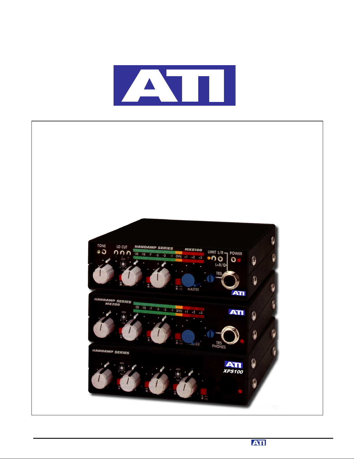
MX200 MX200C MXS100
XPS100 XPS200
STEREO MIXERS and EXPANDERS
OPERATING AND MAINTENANCE MANUAL
Page 2

!"#!$%&'
The ()%*++'is a three input miniature stereo mixer designed for demanding inthe-field use in broadcast ENG (Electronic News Gathering) and Field Production
applications. The MXS100 incorporates the functions required by news
professionals, sports announcers, film and video sound engineers into a tiny,
lightweight and rugged package.
The MXS100 Stereo Field Mixer is ideal for field use with DAT and other high
quality recording devices since it has extremely low input noise, wide, smooth
frequency response and low harmonic and IM distortion. Active balanced input
and output circuits eliminate transformer-induced microphonics, ringing, transient
overshoot and low frequency distortion. Digital compatible dynamic range of
98dB is achieved at normal operating control settings. Full 18dB headroom
above 0VU (+4dBm) is augmented with a fast, low distortion limiter. A built-in
tone oscillator and slate microphone make it easy to set levels and mark takes. A
switchable headphone feed allows program monitoring to one ear with a directors
cue fed to the other. A simple, foolproof optional gel cell battery power pack
allows extended field operation and fast full dual voltage recharge with no cell
memory deterioration.
The (),++' and (),++-' Stereo Studio Mixers retain the identical high quality
audio performance of the MXS100. They are an excellent choice for use in
studios, TV vans, and with the companion Expanders, makes a very powerful
mixing system in only one rack unit (1 ¾”). The MX200C adds an output limiter to
the basic MX200 features.
The companion )!%*++' Input Expander adds four switchable XLR
Microphone/Line inputs with pan pots and switched 24VDC phantom microphone
power.
The companion )!%,++'Stereo Line Input Expander adds two stereo -10/+4 line
inputs with close tracking VCA stereo level controls.
The MXS100/ MX200/ MX200C mixers may be used alone or in combination with
the XPS100 and/or XPS200 expanders for any application requiring a compact,
rugged and professional sounding mixing or input selection system. Several
expanders may be added for up to a 23 input system with minimal noise buildup
in the mixing system. Several power modules are available including both
replaceable and rechargeable 24V battery packs, DC-to-DC step-up converters
for 6 to 18V automotive or belt pack battery power and plug-in 24VDC wall mount
power supplies.
An optional rugged Field Pack carry bag includes side protection plates for the
mixer with quick-change slide mounts for the battery packs.
Page 3

.&%-#/!0/$1'
'
()%*++'%0&#&$'2/&3.'(/)&#'
Three XLR inputs with plug programmable phantom power and front panel
MIC/LINE switches drive low noise instrumentation preamplifiers with a wide
range of internally selectable gains to accommodate either high output wireless
or low output boom microphones. Front panel switches activate individual two
pole LO-CUT filters to block bumps, thumps and wind noise.
Center-detent PAN pots feed the stereo mix busses along with a switched TEST
TONE oscillator and a momentary switched SLATE microphone to easily mark
takes. Bright, intense LED bargraph VU meters monitor the line level outputs and
are easily viewed even in bright sunlight. A LIMIT indicator and switch shows
peaks and controls limiter action. The MXS100 provides high level active XLR
stereo line outputs to drive either balanced or unbalanced external loads of 600
ohms or higher. Rear panel switches individually select microphone or line output
levels. A stereo TAPE OUT jack provides an isolated -10dBu for an external
recorder.
A front panel headphone switch selects either stereo program (L/R) or monosummed program with cue (L+R/Q) as an input to the stereo headphone
amplifier. A stereo TAPE IN jack routes an external -10dBu monitoring signal to
the headphone amplifiers in place of the stereo program feed. A recessed,
thumbnail operated headphone level control minimizes panel clutter and once
set, tracks the MASTER output. An external CUE input jack or a pre-fader cue
from any of the three inputs may be jumper plug programmed to the headphone
cue circuit. The expansion buss input allows interconnection of two MXS100s or
the addition of one or more companion XPS100 Mic Expanders or XPS200
Stereo Line Expanders.
All panel controls, internal adjustments, and jumper plugs are clearly labeled.
'
(),++4'(),++-'%0&#&$'%0"./$'(/)&#%'
The MX200 and MX200C Stereo Studio Mixers are also three input stereo mixers
with front panel selection of microphone or line input levels. Phantom power is
internally jumper plug programmable to any microphone input. Detented Pan
Pots feed fader output to the stereo mix busses. A close tracking VCA stereo
MASTER level control feeds stereo high-level line output stages. The outputs
comfortably drive either balanced or unbalanced output loads of 600 ohms or
greater. Bright LED VU meters and a stereo headphone amplifier monitor the
program outputs. XLR output connectors are standard. A rear panel Expander
input allows interconnection of two mixers or the addition of one or more
companion XPS100 or XPS200 Expanders. The MX200C adds a switched low
distortion compressor/limiter and peak indicating LED to the basic MX200 mixer
features.
Page 4

INPUT EXPANDERS
The companion )!%*++' Input Expander provides four XLR microphone/line
inputs with pan pots and switched phantom power. The )!%,++' Stereo Line
Input Expander controls two stereo -10/+4 XLR line level sources with tight
tracking stereo VCA level controls. The XPS100 and XPS200 are supplied with
interconnecting expansion cables for the audio and DC connections to the
MXS100, MX200 or MX200C.
'
'
!$5&#'
A MXS100, MX200 or MX200C Mixer and a pair of companion Expanders can
comfortably share a single WA100-1, 24VDC / 400mA. wall mount power supply.
220VAC and 50Hz power supplies are available for offshore use. The Mixers can
also be powered directly by a PPA-1 rechargeable 24VDC battery pack or by a
DCA100 DC to DC step-up converter connected to 6 to 18VDC automotive, belt
packs, NP1s or 12V gel cell batteries. The PPA-1 and DCA100 can both mount
to the mixer chassis as an integrated system.
The BBU100 is a replaceable 9V battery pack that can be quick change, slide
mounted with the PROK-1 accessory.
'
'
($"10/16'
Accessory protective side plates (PROK-1) extend past both front knobs and rear
connectors and will allow no damage to the unit. The PROK-1 includes quickchange slides for the battery and converter modules. An attractive protective
carrying bag with shoulder strap is available (ABAG-1) and includes the PROK-1
protection plates. Up to three NANOAMPS will mount side-by-side in only one
rack unit using the available rack mounting kits. NANOAMPS may also be neatly
stacked or mounted side by side on your desk with the available angled desk
mounting kits.
'
'
-/#-"/0'.&%-#/!0/$1'
The input stages of the MXS100, MX200, MX200C and XPS100 are identical.
They are designed around a very low noise and low distortion, balanced and
floating input, instrumentation amplifier. The SSM2017 is one of the latest
generations of devices designed specifically for use as a low noise microphone
amplifier. In addition to ultra low noise and distortion, it boasts a very high slew
rate of 17V/µs virtually eliminating slew induced Transient Intermodulation
Distortion. The direct balanced low noise inputs eliminate the need for input
transformers and avoid their distortion, transient overshoot, roll offs and
microphonics. The input preamp stages can operate at a MIC gain of 30, 40 or
50dB as selected by an individual jumper plug for each input. To access the
jumper plugs, remove the four cover screws (top two on each side) and pull the
top cover up and off. For 30dB operation, remove the gain jumper plug
completely or plug it on to only one pin for safekeeping. The preamps have a
Page 5

high direct input clipping level of -12dBu (260mV peak) in the 30dB position and
optimum noise performance of -126dBm EIN (Equivalent Input Noise) at 50dB
gain. In the LINE input switch position, preamp gain is unity and peak line level
inputs of +18dBu are accepted with nominal inputs adjustable over the range of 10 to +4dBu.
'
'
!789:;<'!;=>?'
Phantom powered microphones will see a regulated +20VDC, open circuit,
through a split and balanced 1660-ohm equivalent resistance. This provides over
+12VDC to the typical 4ma powered microphone. Phantom power is individually
selected for each input with a jumper plug labeled PH PWR placed in the ON
position. Moving the plug to the OFF position removes phantom power and
grounds the phantom power network. Phantom power is automatically removed
when LINE inputs are selected. The phantom power regulator prevents sub-sonic
oscillations and line bounce on the phantom power supply.
'
'
3;='-@:'2AB:>?C'D'()%*++';9BE'
Individual two pole active low cut filters for the reduction of thumps, bumps, and
small hurricanes are controlled by front panel toggle switches. The -3dB corner
frequency is 125Hz with 30dB roll off at 20Hz.
'
'
/9F@:'3>G>B'-;9:?;BC'89H'!89'!;:C'
Each input is adjusted by its' own audio taper potentiometer located after the
preamp stage to minimize noise. These controls are designed to operate in the
ten-to-two o'clock range (-12dB). If you have a preferred position for a particular
mixer input, you can pop out the knob cap and reposition its' reference indicator
line to the twelve o'clock position. Extra knob caps are provided to allow you to
color code the inputs. Yellow, red and green caps are supplied in addition to the
gray caps on the units. To replace the caps, gently pry out the old cap and press
in the new one. Concentric pan pots on each input feed equal signals to left and
right mixing busses in the center position with a reciprocal boost of 1.3dB and a
cut to full off at the extremes.
'
'
Page 6

0;9>'$CIABB8:;?'89H'%B8:>'(AI?;F7;9>'D'()%*++';9BE'
A three position, center off toggle switch in the upper left corner of the panel
selects a 700Hz test TONE oscillator in the up position indicated by an adjacent
green bi-color LED. The tone level is adjusted by R101 and feeds the mixing
buss a factory preset level which will produce an output of +4dBm with the
MASTER control set to the recommended 8dB below maximum.
The built-in SLATE microphone is selected by the same toggle switch in the
momentary down position. The LED will light yellow. The slate microphone gain
is preset, if too high, talk softer, if too low, talk louder. If the yellow light is on
don’t talk about your boss.
'
'
$@:F@:'3>G>B'-;9:?;BC'
The Master control adjusts the Line Outputs as indicated by the LED meter. The
Master control should operate around the 2 o'clock position (-8dB) to maximize
internal headroom and optimize noise performance. Close tracking stereo VCAs
(voltage controlled amplifiers) are operated by the MASTER and PHONES level
controls. VCAs eliminate the stereo image shifts, which could occur due to
possible mistracking of conventional multisection gain controls.
'
'
3&.'(>:>?C'
Ten segment three-color LED bargraph displays meter the outputs with a VU
average response characteristic. Internal calibration pots, R92 (L) and R93 (R),
set the meter readings to indicate 0VU at +4dBm output level and are adjustable
from -10 to +8dBm. LEDs are driven in series to minimize current draw while
providing a bright, color saturated display, which is easily seen, even in bright
sunlight.
'
'
-;<F?>CC;?J'3A<A:>?'D'()%*++'89H'(),++-'
The MXS100 and MX200C incorporate a switched low-distortion compressor/
limiter with a front panel switch and peak indicating LED. The limiter threshold is
adjusted relative to the 0VU meter indication with internal trimpot R110 and is
factory set to +3VU with identical Left and Right signals applied. This setting
corresponds to +9VU peaks for either Left or Right outputs individually.
'
'
Page 7

3A9>'$@:F@:C'
The output stages, A9 and A10, utilize a unique active balanced output driver IC,
the SSM2142, The ICs sense whether the connected load is balanced and
floating or is unbalanced due to either side being grounded. A balanced output
load will be driven with equal and anti-phase levels on the HI and LO output
lines. An unbalanced (one side grounded) load will cause the driver IC to shut off
the signal output to the grounded side of the load and double the output level
applied to the other side, thus maintaining equal output to either type of load. The
output stage will drive loads of 600 ohms and higher. Nominal output is +4dBm
with clipping at +22dBm into balanced loads. Maximum output at# clipping# is
reduced by 6dB when driving an unbalanced load, since the full output swing of
only one driver is available.
'
'
$@:F@:'3>G>B'%=A:I7>C'D'()%*++'
S11 and S12, located on the rear panel directly above their respective output
XLR connector individually insert a 54dB attenuator into the left or right output
line for nominal output at -50dBm microphone level.
'
'
$@:F@:'3>G>B'%>B>I:;?'D'(),++-'89H'(),++'
Two internal jumper plugs located directly behind the output XLR connectors
select either full line level at +4dBm or attenuated microphone level at -50dBm.
'
'
K>8HF7;9>'$@:F@:'3>G>B'
A front panel 1/4” TRS jack and thumbnail-adjust headphone gain control
provides an isolated stereo program output for headphones. The headphone
output provides 100mW to phones of up to 600-ohm impedance and reduced
levels into higher impedance phones.
'
'
K>8HF7;9>'!?;L?8<'J'-@>'%=A:I7'D'()%*++';9BE'
A panel toggle switch allows selection of normal stereo program monitoring or
summed L+R into one side of the headset and an amplified CUE feed into the
other side. A rear panel external CUE input or a jumper plug programmed and
amplified pre-fader cue from any of the three mixer inputs may be fed into the
headphone CUE circuit. The external CUE input is a 2.5mm TS jack. The
external CUE feed should supply -10dBu (.25V) nominal level into 20Kohms. The
pre-fader cue jumper plugs are labeled CUE1, CUE2 and CUE3.
'
'
Page 8

08F>'/94'08F>'$@:'D'()%*++';9BE'
Rear mounted stereo 3.5mm TRS jacks provide a -10dBu high impedance,
unbalanced Tape Output to recorders and a matching -10dBu Tape Input for
playback monitoring. Use of the Tape Out jack will not affect the Program output
signal. Use of the Tape In jack interrupts the Program signal feed to the internal
headphone monitor and substitutes the Tape playback signal.
'
'
&MF89CA;9'/9F@:C'
A 1/8" TRS (Tip-Ring-Sleeve) jack, J10 mounted on the rear panel feeds the
stereo mixing buss to allow interconnection of two mixers or the addition of
XPS100 and XPS200 input expanders. The tip and ring float at half the supply
voltage and must not be externally grounded. These points are zero impedance,
current summing nodes on which you should normally be able to measure
nothing other than a DC voltage.
'
'
&MF89CA;9'$@:F@:C'D')!%*++'89H')!%,++'
The XPS100 and XPS200 Expanders amplified mixing buss outputs appear on
rear panel paralleled 1/8" TRS jacks, J7 and J8. The nominal output is +4dBu
unbalanced through a 287Kohm source resistance to feed the current summing
expansion inputs of the MXS100 or MX200. The paralleled jacks, J7 and J8,
allow multiple Expanders to be looped together and into the MXS100. Internal
jumpers can bypass the 287Kohm resistors to allow direct use of the Expander
outputs for low impedance loads down to 600 ohms.
'
'
!;=>?'%@FFBA>C'
NANOAMPS require 22 to 30VDC from an external power source. The DC power
connector is wired with the center pin negative and the outer cylinder positive. A
series diode and a thermal overload device protect the unit from reversed polarity
DC input. The mixers and expander incorporate an "artificial ground" power
supply splitting circuit to continuously track the DC input voltage and provide a
center point voltage reference for the audio stages.
A low dropout regulator provides a regulated 20.2VDC for phantom powering
microphones from inputs as low as 21VDC. Active regulation of the phantom
power supply helps eliminate any possibility of oscillation due to unbalanced
loading of the phantom supply by the microphone.
Several amplifiers can share a common external 24VDC "Wall Wart" type power
supply for fixed installations. A pair of loop-thru DC connectors on the rear of
each module permits several units to be daisy-chained with P/N20602-1 DC
power cables to a single WA100 power supply. Each Expander is supplied with a
set of loop-thru DC and audio cables for easy interconnect to a companion Mixer.
Page 9

The WA100 is a 400mA supply. A MXS100 or MX200 or MX200C draws about
160mA, a XPS100 draws 100mA and a XPS200 draws 70mA; therefore, one
mixer could be combined with two XPS100s or three XPS200s on a single power
supply module. Any combination of NANOAMPS which add up to less than
400mA can be powered by a single WA100 supply.
'
'
NO00&#P'!$5&#'
Several battery power systems are available for field powering of the MXS100,
MX200C or MX200. The BBU100-1 houses four 9V alkaline or lithium batteries
and will power the MXS100 for three to five hours.
The PPA-1 rechargeable gel-cell pack powers a MXS100 for approximately five
hours and can be recharged overnight with the included dual-mode charger. The
PPA-1 is capable of approximately 500 charge-discharge cycles.
The DCA100 DC to DC Converter accepts inputs from 6 to 18 VDC and outputs
24VDC to operate a mixer from 6.0 or 7.2V camcorder Ni-Cd, belt-pack Ni-Cd
packs, automotive 12V or 12.0 to 14.4 V NP-1 batteries. The DCA100 requires a
standard 4 pin XLR input connector from the battery source (pin 4 positive, pin 1
ground). Battery clips (Hawk-Woods Co. # NPA - XLR) are available for NP-1
type 13.2V NiMH batteries, which can power a MXS100 thru a DCA100 for up to
10 hours.
The BBU100-1, PPA-1 and DCA100 can all mount directly to the underside of the
NANOAMP case or slip into the quick-change slide mounts provided with the
PROK-1 protection kit or the ABAG-1 carry case. A NP-1 type battery and a
spare can be Velcro to the inside of the carrying case.
'
'
/1%0O33O0/$1'
'
"1!O-Q/16'
Inspect the equipment. Shake it to see if anything is rattling around inside. If
there is any visible damage to the unit or to the box it came in, contact the factory
but do not return anything to ATI without prior authorization and shipping
instructions. It may be necessary to have the shipping company inspect the unit
and the box at your location. Count the pieces! Don't throw out the boxes and
packing material until you are sure you have everything that is coming to you.
The XPS100 and XPS200 come with an audio cable, P/N20612-2, a DC cable,
P/N20602-1, and an instruction book. The MXS100 comes with an instruction
book and a mating 2.5mm T-S plug for the CUE input. The MX200 and MX200C
only come with an instruction book. Mixers need either their own separately
ordered WA100 power supply, a optional battery supply, a DC Converter or
a DC cable, P/N20602-1 to share the supply of another NANOAMP.
Page 10

Rack and desk mounting hardware may be packed in with the unit even though
ordered separately. Wall mount power supplies must be ordered separately but
may either be included with the unit or shipped in their own box. Optional PPA-1
Battery Packs and DCA100-1 DC Converters may be shipped already mounted
to the bottom of the Mixer or may be separately packaged so you have the fun of
putting them together (only four #4 X 5/16” screws).
'
'
%&0"!'O.R"%0(&10%'
The following adjustments require that the mixer cover be removed and should
be made before rack mounting while the mixer is accessible. Remove the top
cover by removing four Phillips head screws (top two on each side).
'
'
!KO10$('!$5&#'
Locate the red jumper plugs labeled PH PWR associated with each input. Move
the desired plug from OFF to ON as required.
'
'
(/-#$!K$1&'6O/1'
Locate the blue jumper plugs labeled GAIN associated with each input. The two
positions are labeled 40 and 50dB. For 30dB gain mount plug by only one pin
(leaving circuit open). Select a gain appropriate for the microphone in use such
that peak microphone output voltage plus the set preamp gain will not exceed the
clipping point of the preamp at +18dBu. Extremely sensitive shotgun
microphones used in a close talking application may require an in-line attenuator
to prevent input overload.
'
'
K&O.!K$1&'-"&D'()%*++'
If it is desired to use one of the input channels for CUE move the appropriate
black jumper plug from OFF to CUE.
'
'
$"0!"0'3&S&34'(/-';?'3/1&'D'(),++-4'(),++'
Locate the two large jumper plugs located just behind the output XLR
connectors. Move them to the Line (+4dBm) or MIC (-50dBm) position as
required. The MXS100 has rear panel switches for this function.
'
'
Page 11

$"0!"0'3&S&34'D*+':;'TUHN<'
If a different output level at 0VU meter indication is desired, drive the output to
the desired output level at 1kHz as indicated by an external audio voltmeter
connected across the output line and readjust METER CAL-LEFT and METER
CAL-RIGHT trimpots for 0VU meter indications. Note that the MIC output level (if
used) will track the changes made to the LINE output.
'
'
3/(/0&#'0K#&%K$3.'D'()%*++4'(),++-'
To increase the limiter action (by lowering the threshold) rotate the LIMITER
ADJUST trimpot clockwise, to soften the limiter action rotate the pot CCW.
'
#O-Q'($"10/16'
The amplifiers may be rack mounted one, two, or three across in a standard EIA
19" rack and will require only 1 3/4" of vertical space. Rack mount kit P/N20604501 mounts a single unit, P/N20604-502 mounts two units and P/N20604-503
mounts three units. Each kit provides a different size pair of rack mounting
brackets and one or two horizontal joiner plates, P/N 20580-1, each with four 440 X 5/16" oval head screws. The joiner plates mount into tapped holes on the
bottom of two side-by-side units, using the supplied screws, while the rack mount
brackets mount under the existing 6-32 cover securing screws on the front sides
of the units.
'
'
.&%Q'($"10%'
Single desk mounting kits consist of a pair of angled base plates that mount
under the lower front and rear cover screws of a single unit, to raise and to tilt it
for easy desk use. In addition, one or more sets of vertical stacking plates,
mounting to the upper front and rear cover screws of the bottom unit, allow
multiple units to be stacked. Several units can be desk mounted side-by-side and
even stacked side-by-side using horizontal joiner kits together with mounting
base and stacker kits. P/N20617-501 is the angled base kit. P/N20617-502 is the
base plus one stacker kit (two high). P/N20617-503 is the base plus two stackers
(three high). P/N20617-504 is the stacker kit by itself and P/N20604-504 is a
horizontal joiner kit.
'
'
!#$QD*'!#$0&-0/$1'!3O0&%'89H'ONO6D*'2/&3.'-O##P'NO6'
The Protection Plates PROK-1 (also included as part of the ABAG-1 Field Carry
Bag) are mounted to the sides of the MXS100 by removing the four cover
mounting screws (one side at a time) and replacing them through the mating
holes in the Protection Plate. The Plate should mount with its overhang below the
mixer case and the battery case slide bracket below and toward the mixer.
Page 12

Battery cases slide in from the front and should click into place when fully
inserted. Plug the battery cable into the rear connector of the mixer. The ABAG-1
Carry Bag wraps around the mixer and PROK-1 plates from below and mounts to
the protection plates with the supplied four screws and washers inserted through
eyelets in the carry bag. Overlap the top folds of the bag with the ATI logo on the
outside. The attached Velcro strips can mount NP-1 batteries with mating strips
of Velcro.
'
'
O"./$'-$11&-0/$1%'
XLR type inputs and outputs are wired per figure 1 with pins 2 as HI and pins 3
as LOW. Pin 1 of all input connectors is permanently grounded and is the cable
shield and DC return connection for phantom microphone power.
Active balanced outputs require a reference ground connection to the receiving
device for proper operation. The rack frame or a studio buss connection can
provide this ground if the output cable shield does not carry it through.
'
'
!$5&#'./%0#/N"0/$1'
Input Expanders should be looped through each other then into the mixer using
the DC jumper cables P/N20602-1. Hum and noise performance of the
expanders can be degraded by poor DC ground connections between it and the
mixer. Use of the recommended rack and desk mounting kits will assure a good
ground connection between units by firmly strapping their chassis together.
CAUTION! The outer shell of the DC interconnect cables is positive relative to
the chassis. Do not allow a DC cable plugged into a powered unit to hang loose
where it might short against the chassis or rack frame.
'
'
$!0/$1%'
,V+SO-'
Power modules and rechargeable battery packs for local operation in areas
outside of the USA are available. See a current ATI price list for part numbers.
'
'
NO00&#P'$!&#O0/$1'
The DCA100-1 DC to DC converter allows use of an MXS100 with mobile, belt
pack and gel cell 6 to 18 VDC battery power. The DCA100-1 can mount directly
to the underside of the MXS100 with the screws provided or fit into the slide
mounts of the PROK-1 for easy interchange with battery packs.
The BBU100-1 Battery Pack holds four replaceable 9V alkaline or lithium cells
and will power a single MXS100 for approximately three hours.
Page 13

The PPA-1 Rechargeable 24VDC Battery Pack mounts directly to the underside
of the MXS100 and allows approximately four hours of remote operation. A dual
mode charger is included for quick (3 - 4 hours) recharge. The PPA-1 uses
rugged sealed gel cells capable of 500 charge - discharge cycles (typical) with no
memory effect degradation. Replacement batteries are readily available from
distributor stock or from ATI.
'
'
(O/10&1O1-&'
There is no routine maintenance required by your NANOAMP. If you have a
problem, check panel LED indicators to assure that the units have DC power,
eliminate by substitution microphones, input and output cables, connectors,
downstream devices, Mixer to Expander interconnect cables and Wall Wart
power supplies. If all else fails, read your warranty in the front of this book (which
probably ran out yesterday) and call us for sympathy and overpriced parts.
'
'
!;=>?'%@FFBE'3>G>BC'
The recommended loaded DC input voltage range is 22VDC minimum to 32VDC
maximum. The audio circuits continue to work with reduced headroom below
22VDC but the VU meter will blink at full scale. Momentary surges up to 36VDC
will cause increased internal heating, but above 36V call ATI for some expensive
ICs.
'
'
$F>?8:A9L'!;A9:C'
An internal reference voltage equal to 1/2 the supply voltage is generated by A15
in the MXS100 and MX200 and by A7 in the XPS100. All IC inputs and outputs
should show a DC level equal to this voltage when measured with a high
impedance meter. XLR audio inputs and outputs are capacitor coupled and
ground referenced. The expansion buss input is at the DC reference level and
must not be accidentally grounded by dangling audio interconnects cables.
'
'
Page 14

%=A:I7'(8A9:>989I>'
The front panel MIC/LINE push-button switches have good wiping contacts and
should need little attention. The switches are sealed and impossible to clean, in
addition, most spray solvents will wash out the internal lubricant and cause
premature mechanical failure. A good fix, if the switches ever get noisy, is to sit
down at the unit, think about your girlfriend (or Madonna or Mae West, depending
on your age bracket) and push those little red buttons about 500 times each. If
that doesn't cure the problem, call us for more sympathy and a high-priced
replacement. Those tiny toggle switches on the MXS100 panel are far more
rugged than they appear because they bend rather than break. Gold contacts
help them stay quiet. No routine maintenance required or recommended.
!;:>9:A;<>:>?C'
Input Gain controls are 10Kohm audio taper pots with a 10K linear concentric
Pan pot. Replacements are our P/N10088-1. The Master and Phones pot is a
50Kohm linear taper pot, our P/N10089-1.
'
Page 15

SPECIFICATIONS
Output Level: +4dBm Nominal into 600 ohm balanced or
unbalanced loads; +22dBm Max.
Distortion: .0-20Hz to 20kHz at +4dBm.
Response: +/- .25dB, 5 to 100kHz
Noise: Microphone input: EIN= -126dBm; 50dB input gain.
Line Input: EIN= -84dBm; unity input gain
Gain: Mic Inputs: +82dB Max; Line Inputs: +42dB Max.
Headphone Output: 100mW to 600/150-ohm phones, TRS jack.
Limiter: 5:1 slope, Attack time 25ms, Recovery time 200ms for
10dB change
Phantom Power: +20VDC
DC Power: 24VDC Nom. 160mA MXS100, MX200C or MX200
=160mA, XPS100 = 90mA
XPS200 = 60mA
Dimensions in.(cm.): 1.75(4.45)H X 5.6(14.22)W X 5.75(14.6)D; 1.25lbs,
.57Kg.
MODELS AVAILABLE:
MXS100 Stereo Three Input Mic/Line Field Mixer
MX200C Stereo Three Input Mic/Line Studio Mixer with Limiter.
MX200 Stereo Three Input Mic/Line Studio Mixer.
XPS100 Stereo Four Mic/Line Input Expander.
XPS200 Stereo Two Stereo Line Input Expander.
Note: All units require a 24VDC power supply, which is ordered separately.
Several amplifiers can share a single supply-using loop thru DC cable (P/N
20602-1). Do not exceed rated supply current.
Page 16

ACCESSORIES
WA100-1 Wall mount power supply (UL), 24VDC @ .4 amp, 115
VAC/60 Hz.
WA100-2 Tabletop power supply, 24VDC @ .4 amp, 230 VAC/50-60
Hz with IEC 320 male 3 pin AC input connector. User
supplies matching AC line cord for local power system.
20602-1 DC power cable assembly for looping the DC power
between.
BBU100-1 Battery Pack unit houses four 9V alkaline or lithium batteries
(batteries not included). Nominal 3-hour operational life.
DCA100-1 DC to DC converter powers units from 12VDC mobile, belt
pack, NP1 and Gel cell batteries. Supplies 24VDC @ .2amp
maximum.
PPA-1 24VDC Rechargeable Battery Pack with dual mode fast
charger. Mounts to mixer. Four-hour nominal operation.
ABAG-1 Carry Case with side protector plates and strap holds
MXS100 with DCA100-1, PPA-1or BBU100-1
PROK-1 Bolt-on side plates protect controls and connectors and
provide slide mounts for battery packs.
Rack Mount Kits:
21075-501 Side-by-side mount for up to three units.
Desk Mount Kits:
20617-501 Angled Desk Mount Base
20617-502 Angled Desk Mount Base and One Stacker (2 units high)
20617-503 Angled Desk Mount Base and Two Stackers (3 units high)
20617-504 Stacker (2 units high)
20604-504 Horizontal Joiner (2 units side-by-side)
 Loading...