

Page 1
ATI Single-Axis, Radially-Compliant
Robotic Deburring Tools
Flexdeburr™
(Model 9150-RS-340)
Product Manual
Document #: 9610-50-1016
Engineered Products for Robotic Productivity
Pinnacle Park • 1031 Goodworth Drive • Apex, NC 27539 USA • Tel: +1.919.772.0115 • Fax: +1.919.772.8259 • www.ati-ia.com • Email: info@ati-ia.com
Page 2

Manual, Flexdeburr, RS-340
Document #9610-50-1016-08
Foreword
CAUTION: This manual describes the function, application, and safety considerations of this
product. This manual must be read and understood before any attempt is made to install or
operate the product, otherwise damage to the product or unsafe conditions may occur.
Information contained in this document is the property of ATI Industrial Automation, Inc. (ATI) and shall not be
reproduced in whole or in part without prior written approval of ATI. The information herein is subject to change without
notice. This manual is periodically revised to reect and incorporate changes made to the product.
The information contained herein is condential and reserved exclusively for the customers and authorized agents of ATI
Industrial Automation and may not be divulged to any third party without prior written consent from ATI. No warranty
including implied warranties is made with regard to accuracy of this document or tness of this device for a particular
application. ATI Industrial Automation shall not be liable for any errors contained in this document or for any incidental
or consequential damages caused thereby. ATI Industrial Automation also reserves the right to make changes to this
manual at any time without prior notice.
ATI assumes no responsibility for any errors or omissions in this document. Users’ critical evaluation of this document is
welcomed.
Copyright by ATI Industrial Automation. All rights reserved.
How to Reach Us
Sale, Service and Information about ATI products:
A TI Industrial Automation
1031 Goodworth Drive
Apex, NC 27539 USA
www.ati-ia.com
Tel: +1.919.772.0115
Fax: +1.919.772.8259
E-mail: info@ati-ia.com
Technical support and questions:
Application Engineering
Tel: +1.919.772.0115, Option 2, Option 2
Fax: +1.919.772.8259
E-mail: mech_support@ati-ia.com
Pinnacle Park • 1031 Goodworth Drive • Apex, NC 27539 USA • Tel: +1.919.772.0115 • Fax: +1.919.772.8259 • www.ati-ia.com • Email: info@ati-ia.com
2
Page 3

Manual, Flexdeburr, RS-340
Document #9610-50-1016-08
Table of Contents
Foreword .......................................................................................................................................... 2
Glossary ........................................................................................................................................... 5
1. Safety ......................................................................................................................................... 6
1.1 ExplanationofNotications .........................................................................................................6
1.2 General Safety Guidelines ............................................................................................................6
1.3 Safety Precautions ........................................................................................................................7
2. Product Overview ..................................................................................................................... 8
2.1 Tool Collet Systems ......................................................................................................................9
2.2 Technical Description ...................................................................................................................9
2.2.1 Environmental Limitations ..................................................................................................9
2.2.1.1 Operation ............................................................................................................9
2.2.1.2 Storage .............................................................................................................10
2.2.2 Compliance Unit Performance ......................................................................................... 11
3. Installation .............................................................................................................................. 12
3.1 Transportation and Protection during Transportation ............................................................. 12
3.2 Inspection of Condition When Delivered ..................................................................................12
3.3 Unpacking and Handling ............................................................................................................12
3.4 Storage and Preventive Maintenance during Storage .............................................................12
3.5 Side Mounting Installation ..........................................................................................................13
3.6 Axial Mounting Installation .........................................................................................................14
3.7 Pneumatics ..................................................................................................................................15
4. Operation ................................................................................................................................ 17
4.1 Safety Precautions ......................................................................................................................17
4.2.1 Air Quality .........................................................................................................................18
4.2.2 No Lubrication ..................................................................................................................18
4.2.3 Bur Selection, Design, and Maintenance .........................................................................18
4.2.4 Deburring Tool Approach Path Should be Slow and at an Angle .....................................18
4.2.5 No Axial Loading ..............................................................................................................18
4.2.6 Perpendicular Loading .....................................................................................................18
4.2 Normal Operations ......................................................................................................................18
4.3 Flexdeburr Working Environment .............................................................................................19
4.2.7 Program the Robot to Incorporate 50% Compliance Travel of the Tool ...........................19
4.4 Tool Center Point (TCP) Position and Programming ...............................................................20
4.5 Cutter Operation and Bur Selection ..........................................................................................22
4.5.1 Bur Selection ....................................................................................................................22
Pinnacle Park • 1031 Goodworth Drive • Apex, NC 27539 USA • Tel: +1.919.772.0115 • Fax: +1.919.772.8259 • www.ati-ia.com • Email: info@ati-ia.com
3
Page 4

Manual, Flexdeburr, RS-340
Document #9610-50-1016-08
5. Maintenance ............................................................................................................................ 25
5.1 Pneumatics ..................................................................................................................................25
5.2 Lubrication ...................................................................................................................................25
5.3 Boot Inspection ...........................................................................................................................25
5.4 Bur Inspection .............................................................................................................................25
6. Troubleshooting and Service Procedures ...........................................................................26
6.1 Troubleshooting ..........................................................................................................................26
6.2 Service Procedures .....................................................................................................................27
6.2.1 Bur and Collet Replacement ............................................................................................27
6.2.2 Turbine Motor Replacement .............................................................................................29
6.2.3 Ring Cylinder Assembly Replacement .............................................................................31
7. Serviceable Parts ................................................................................................................... 33
7.1 Accessories Tools, and Optional Replacement Parts .............................................................33
8. Specications ......................................................................................................................... 34
9. Drawings ................................................................................................................................. 35
9.1 RS-340 Geometry and Mounting ................................................................................................35
9.2 RS-340 Serviceable Parts Drawing ............................................................................................36
10. Terms and Conditions of Sale ............................................................................................... 37
10.1 Motor Life and Service Interval Statement ................................................................................38
10.1.1 Turbine Motor Products (Flexdeburr (RS) models) ..........................................................38
Pinnacle Park • 1031 Goodworth Drive • Apex, NC 27539 USA • Tel: +1.919.772.0115 • Fax: +1.919.772.8259 • www.ati-ia.com • Email: info@ati-ia.com
4
Page 5

Manual, Flexdeburr, RS-340
Document #9610-50-1016-08
Glossary
Term Denition
Adapter Plate
Air Filter
Air Turbine Air motor that drives the spindle.
Bur
Burr Any unwanted, raised protrusion on the work piece.
Climb Milling
Chattering Machine vibrations. The cutting tool bounces as it contacts the work surface.
Coalescing Filter Device designed to remove the liquid aerosols from the supply air lines.
Collet Gripping device used to hold cutting tools in the spindle.
Compliance
Conventional Milling
End-Effector Tool used by the robot to perform a particular function
Flexdeburr Product family name for ATI’s line of radially compliant deburring tools.
Main Housing The main cylindrical body of the unit which includes the mounting features.
Positive Stop The tool has contacted a physical limitation and can no longer move.
Qty Quantity.
Regulator
Rear Housing
RS Single-axis radially-compliant.
Solenoid Valve Electrically controlled device for switching air supplies on and off.
Spindle The rotating portion of the deburring tool assembly.
Turbine Air motor that drives the spindle.
Device for attaching the deburring tool to either a robot ange or a stationary
mounting surface.
Device for removing contamination from the air supply lines. Typically refers to
removal of the particulates.
Cutting tool used to remove the burrs from the work piece. Alternatively
referred to as a rotary le, cutter, or bit.
Cutting method where the direction of the cutter rotation and tool motion are
the same.
The ability of the spindle to passively move in the response to protrusions on
the or deviations of the work piece.
Method of cutting where the direction of the tool motion is opposite that of the
tool rotation.
Device used to set and control the supplied air pressure to lower acceptable
levels.
Rear cover to the main housing. The body includes a connection port for
compliance and motor air.
Pinnacle Park • 1031 Goodworth Drive • Apex, NC 27539 USA • Tel: +1.919.772.0115 • Fax: +1.919.772.8259 • www.ati-ia.com • Email: info@ati-ia.com
5
Page 6
Manual, Flexdeburr, RS-340
Document #9610-50-1016-08
1. Safety
The safety section describes general safety guidelines to be followed with this product, explanations of the
notications found in this manual, and safety precautions that apply to the product. More specic notications are
imbedded within the sections of the manual where they apply.
1.1 ExplanationofNotications
The following notications are specic to the product(s) covered by this manual. It is expected that the user
heed all notications from the robot manufacturer and/or the manufacturers of other components used in the
installation.
DANGER: Notication of information or instructions that if not followed will result in
death or serious injury. The notication provides information about the nature of the
hazardous situation, the consequences of not avoiding the hazard, and the method for
avoiding the situation.
WARNING: Notication of information or instructions that if not followed could result
in death or serious injury. The notication provides information about the nature of the
hazardous situation, the consequences of not avoiding the hazard, and the method for
avoiding the situation.
CAUTION: Notication of information or instructions that if not followed could result
in moderate injury or will cause damage to equipment. The notication provides
information about the nature of the hazardous situation, the consequences of not
avoiding the hazard, and the method for avoiding the situation.
NOTICE: Notication of specic information or instructions about maintaining, operating,
installing, or setting up the product that if not followed could result in damage to equipment. The
notication can emphasize, but is not limited to: specic grease types, best operating practices,
and maintenance tips.
1.2 General Safety Guidelines
Prior to purchase, installation, and operation of the Flexdeburr product, the customer should rst read and
understand the operating procedures and information described in this manual. Never use the deburring tool
for any purposes, or in any ways, not explicitly described in this manual. Follow installation instructions and
pneumatic connections as described in this manual.
All pneumatic ttings and tubing must be capable of withstanding the repetitive motions of the application
without failing. The routing of the pneumatic lines must minimize the possibility of stress/strain, kinking,
rupture, etc. Failure of the critical pneumatic lines to function properly may result in the equipment damage.
Pinnacle Park • 1031 Goodworth Drive • Apex, NC 27539 USA • Tel: +1.919.772.0115 • Fax: +1.919.772.8259 • www.ati-ia.com • Email: info@ati-ia.com
6
Page 7

Manual, Flexdeburr, RS-340
Document #9610-50-1016-08
1.3 Safety Precautions
CAUTION: Do not use spare parts other than original ATI spare parts. Use of spare
parts not supplied by ATI can damage equipment and void the warranty. Always use
original ATI spare parts.
CAUTION: Do not perform maintenance or repair on the Flexdeburr product unless the
tool is safely supported or placed in the tool stand and air has been turned off. Injury
or equipment damage can occur with tool not placed in a tool stand and air remaining
on. Place the tool safely in the tool stand and turn off the air before performing
maintenance or repair on the Flexdeburr product.
NOTICE: Turbine motors are not serviceable at this time. Refer to Section 10—Terms and
Conditions of Sale. To maximize the life of turbine motor products the customer should follow
closely the normal operation procedures outlined in the product manual. The air must be totally
lube free and ltered to remove particulates and moisture. Exposing the turbine motors to oil in
the air supply results in premature failure.
Pinnacle Park • 1031 Goodworth Drive • Apex, NC 27539 USA • Tel: +1.919.772.0115 • Fax: +1.919.772.8259 • www.ati-ia.com • Email: info@ati-ia.com
7
Page 8
Manual, Flexdeburr, RS-340
Document #9610-50-1016-08
2. Product Overview
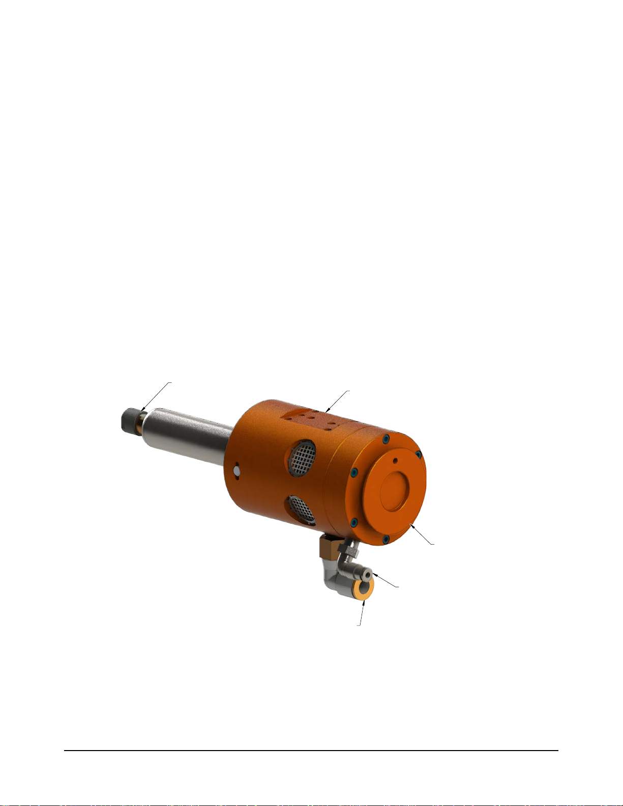
The single-axis radially-compliant (RS) Deburring tool, also known as Flexdeburr, is robust, high-speed and
lightweight air turbine-driven deburring units for deburring aluminum, plastic, steel, etc. with a robot or CNC
machine. The RS deburring tool is especially suited for removal of parting lines and ash from the parts. However,
its exible design allows it to be used in a wide variety of applications.
The RS deburring tool’s pneumatically controlled, articulated design allows the cutting bit to follow the part prole
and compensate for surface irregularities while maintaining a constant, settable force. This allows high feed rates
with uniform quality in any orientation. The tool requires no oil, allowing clean exhaust air to be vented directly
into the work environment.
Compliance is supported by air pressure applied to the shaft of the unit and is used to perform consistent deburring
on irregular part patterns. The motors internal governor maintains high spindle speeds for optimum surface
nish. The RS deburring tool also utilizes standard industrial tungsten-carbide bits which allows for adaptation to
changing assembly lines and part requirements.
The RS-340 provides for (2) mounting types, a side mounting and an axial mounting. The side mounting provides
(2) locating dowel pins and (4) threaded holes. The axial mounting utilizes a tapered ange that requires an adapter
plate. Custom adapter plates for both side and axial mounting are available from ATI. Refer to Section 9—Drawings
for more information.
The RS-340 is equipped with a 1/2" (12 mm on the Euro models) push-to connect tting to supply the motor air and
a 5/32" (4 mm) Push-to Connect tting to supply the compliance air.
A tool collet system secures the bur tool. Many collet sizes and a various selection of tools are available to
accommodate a wide variety of applications.
Figure 2.1—RS-340 Deburring Tool
Tool Collet System
Side Mounting
Axial
Mounting
Compliance Air
Connection
Motor Air
Connection
Pinnacle Park • 1031 Goodworth Drive • Apex, NC 27539 USA • Tel: +1.919.772.0115 • Fax: +1.919.772.8259 • www.ati-ia.com • Email: info@ati-ia.com
8
Page 9

Manual, Flexdeburr, RS-340
Document #9610-50-1016-08
2.1 Tool Collet Systems
All Flexdeburr products utilize removable collets to grip customer supplied cutting tools. Different collet
diameters may be substituted to retain numerous cutter shank diameters. The collet retaining nut is loosened
to open the collet allowing cutting tools to be removed and inserted. Once the tool is set to the desired depth,
spanner wrenches are used to tighten the collet nut causing the collet to collapse and secure the cutting tool.
The turbine motor design does not allow the installation of the quick-change or drawbar collet systems.
The standard tool holding system for Flexdeburr products is an economical, proprietary, single-angle collet
design utilizing (3) gripping ngers. This is suitable for most applications where industry standard shank
diameter cutting tools are used and runout tolerances of up to 0.001” (0.025 mm) are acceptable. Special
sizes are available upon request but require custom machining.
2.2 Technical Description
A technical overview of the product is provided in the following tables and graphs. For additional technical
specications, refer to Section8—Specications.
2.2.1 Environmental Limitations
2.2.1.1 Operation
Installation
position
Temperature
range
Table 2.1—Operation
Mounted to robot by means of the side mounting
pattern or rear adapter ange. Refer to Section 3.5—
Side Mounting Installation and Section 3.6—Axial
Mounting Installation. The ange is specic to
each type of robot. This optional ange is normally
supplied by ATI in a blank form suitable for customer
modication. Refer to Section 9.1—RS-340 Geometry
and Mounting.
Mounted to a table or stand by means of the bench
adapter (the robot is carrying the work piece).
5° C–35° C
41° F–95° F
The tool requires the following:
• Clean, dry, ltered, non‑lubricated air.
• A coalescing lter and lter elements rated
5 micron or better.
Utilities
• The motor spindle must be supplied air at
6.2 bar (90 psi).
• The radial compliance (centering) air must be
supplied from a regulated source between
1.0–4.1 bar (15–60 psi).
Pinnacle Park • 1031 Goodworth Drive • Apex, NC 27539 USA • Tel: +1.919.772.0115 • Fax: +1.919.772.8259 • www.ati-ia.com • Email: info@ati-ia.com
9
Page 10

Manual, Flexdeburr, RS-340
Document #9610-50-1016-08
2.2.1.2 Storage
Temperature
range
Conditions
Table 2.2—Storage
0° C–45° C
32° F–113° F
The tool should be stored in its crate and in a dry
place.
When not in use, keep the unit in its crate If possible.
Consult Section 3.7—Storage and Preventive
Maintenance during Storage of this manual.
Pinnacle Park • 1031 Goodworth Drive • Apex, NC 27539 USA • Tel: +1.919.772.0115 • Fax: +1.919.772.8259 • www.ati-ia.com • Email: info@ati-ia.com
10
Page 11

Manual, Flexdeburr, RS-340
Document #9610-50-1016-08
2.2.2 Compliance Unit Performance
The variation of the compliance force with applied air pressure are illustrated in the following
graph. Measurements may vary from one product to another, and should only be treated as nominal.
The actual force characteristics are dependent on mounting orientation and the condition of the
unit. In applications, where the deburring tool is mounted horizontally, additional compliance air
pressure is required to overcome the weight of the motor. Compliance pressure is also dependent
upon the material of the work piece, type of bur tool, and the amount of material that is removed.
The turbine motor attempts to maintain its full rated speed even under loaded conditions. However,
when extremely heavy cuts are taken, the motor may eventually stall. Therefore, multiple, light
passes are preferred over slow, heavy cuts.
Figure 2.2—RS-340 Compliance Force Curves (Measured at the Spindle Collet)
1.00 1.25 1.50 1.75 2.00 2.25 2.50 2.75 3.00 3.25 3.50 3.75 4.00
9
Compliance Air Pressure (bar)
40
8
7
6
5
4
3
2
15 20 25 30 35 40 45 50 55 60
Compliance Air Pressure (psi)
36
31
27
Axial Force (N)Axial Force (lbs)
22
18
13
9
Pinnacle Park • 1031 Goodworth Drive • Apex, NC 27539 USA • Tel: +1.919.772.0115 • Fax: +1.919.772.8259 • www.ati-ia.com • Email: info@ati-ia.com
11
Page 12

Manual, Flexdeburr, RS-340
Document #9610-50-1016-08
3. Installation
The RS-340 Deburring Tool is delivered fully assembled. Optional equipment such as mounting adapter plates, burr
tools, additional collets will be separate.
3.1 Transportation and Protection during Transportation
The RS deburring tool arrives in packaging to secure and protect it during transportation. Always use this
packaging when transporting the deburring tool in order to minimize the risk of damage.
3.2 Inspection of Condition When Delivered
Upon receipt, the following should be checked:
• Delivery is in accordance with freight documents.
• Packaging is in good condition.
If there is damage to any of the packaging, or if any of the goods have been exposed to abnormal handling,
unpack those parts that may have been damaged for a closer inspection. If necessary, notify ATI for
assistance in evaluation of the product condition.
3.3 Unpacking and Handling
The deburring tool should always be placed inside the accompanying packaging during transportation,
storing and handling.
Pneumatic lines and electrical cables are attached, bundled, and must be strain-relieved in a manner that
allows for freedom of movement during operation.
3.4 Storage and Preventive Maintenance during Storage
The deburring tool should be stored in its packaging when it is not in use. The deburring tool should also be
stored in a dry place.
For long-term storage, the deburring tool should be thoroughly cleaned of any burrs or debris. It should not
be disassembled. Place the deburring tool inside a sealed, plastic bag inside its packaging.
Pinnacle Park • 1031 Goodworth Drive • Apex, NC 27539 USA • Tel: +1.919.772.0115 • Fax: +1.919.772.8259 • www.ati-ia.com • Email: info@ati-ia.com
12
Page 13

Manual, Flexdeburr, RS-340
Document #9610-50-1016-08
3.5 Side Mounting Installation
CAUTION: The length of the fasteners should not interfer with the compliant motion
of the turbine motor spindle. Refer to Section 9—Drawings for the maximum fastener
length. Do not use fasteners that exceed the maximum length; otherwise, damage will
occur.
CAUTION: Lock washers are recommended on all mounting fasteners. Liquid thread
lockers should not be used for the mounting fasteners as this may damage or remove
thread inserts during disassembly.
The side mounting pattern of the RS deburring tool consists of (2) dowel pin holes and (4) of threaded holes
as shown in the following gure. An optional bench mount adapter plate allows the deburring tool to be
permanently attached to a bench or other work surface. If the RS deburring tool is permanently mounted to a
work surface, the robot carries the part to be deburred to the deburring tool.
(4) M5 Socket Head
Figure 3.1—Bench (Side) Installation
Cap Screws
Lock Washer
Benchtop Interface
Plate Assembly
Side Mounting
on Front Housing
Assembly
Pinnacle Park • 1031 Goodworth Drive • Apex, NC 27539 USA • Tel: +1.919.772.0115 • Fax: +1.919.772.8259 • www.ati-ia.com • Email: info@ati-ia.com
13
Page 14

Manual, Flexdeburr, RS-340
Document #9610-50-1016-08
3.6 Axial Mounting Installation
A blank robot adapter plate is also available to allow axial mounting off the rear of the deburring tool
housing. This plate may be modied by the system integrator or by the owner/user of the Flexdeburr. ATI
can provide custom interface plates and adapters upon request. If the RS deburring tool is permanently
mounted to a work surface, the robot carries the part to be deburred to the deburring tool.
Figure 3.2—Axial Installation
Blank Interface
Plate
Axial Mounting Flange
on Rear Housing
Assembly
Clamping Collar
(2) M5 Socket
Head Cap Screws
Pinnacle Park • 1031 Goodworth Drive • Apex, NC 27539 USA • Tel: +1.919.772.0115 • Fax: +1.919.772.8259 • www.ati-ia.com • Email: info@ati-ia.com
14
Page 15

Manual, Flexdeburr, RS-340
Document #9610-50-1016-08
3.7 Pneumatics
Connect the RS deburring tool as shown in the following gure.
CAUTION: Do not use lubricated air with the Flexdeburr. Oil in the air stream will
result in premature failure of the turbine motor and is not covered under warranty. It
is recommended that the customer use a coalescing lter and lter elements that are
rated 5 micron or better.
Figure 3.3—Pneumatic Connections
WARNING: All pneumatic ttings and tubing must be capable of withstanding the
repetitive motions of the application without failing. The routing of the pneumatic lines
must minimize the possibility of over stressing, pullout, or kinking the lines. Failure to
do so can cause some critical pneumatic lines not to function properly and may result in
damage to equipment.
The air supply should be dry, ltered, and free of oil. A coalescing lter with elements rated for 5 micron or
better is required.
A high-ow air pressure control regulator is required to supply the spindle motor at 6.2 bar (90 psi). A
second, precision, self-relieving regulator will supply air for the compliance or centering force.
The compliance force is applied radially and is adjusted until the desired cut is made. The robot’s traversing
speed will also be adjusted to achieve the desired nish.
CAUTION: Pneumatic components used for the motor drive circuit must be capable
of meeting the air consumption requirements (see Section8—Specications). Poor
performance will result, if the correct components are not used.
Conventional, customer-supplied, pneumatic components are used to control the air supply to the deburring
tool. ATI recommends that the user install a high-ow pneumatic pressure regulator (ATI Part #9150-FFR90, or equivalent. See Section8—Specications for the maximum ow requirements) and a high-ow valve
to properly supply a stable air supply of the 6.2 bar (90–95 psi) to the spindle motor. The RS deburring tool
will not operate properly, if the supplied air is below 6.2 bar (90 psi).
Pinnacle Park • 1031 Goodworth Drive • Apex, NC 27539 USA • Tel: +1.919.772.0115 • Fax: +1.919.772.8259 • www.ati-ia.com • Email: info@ati-ia.com
15
Page 16

Manual, Flexdeburr, RS-340
Document #9610-50-1016-08
A second, precision, self-relieving regulator (ATI Part # 9150-P16-B-G, or equivalent) is used to supply the
compliance (centering) mechanism. This pressure corresponds to the side force on the bur. Because very
little air ow is required for the compliance mechanism, a signicantly smaller valve can be used. (Consult
the valve and regulator supplier’s literature when selecting these components).
If the complete work piece can be deburred with equal force, a conventional, manual pressure regulator
can be used for compliance. If the burrs to be removed vary from place to place on the work piece, and this
variation is repeatable for all work pieces of the same type, it may be necessary to adjust the force using an
analog pressure regulator controlled from the robot. An analog output port in the robot or logic controller
will be needed.
Solenoid valves are actuated from the robot or program logic controller by means of a digital output signal.
Function Connection Type Pressure
Table 3.1—Pneumatic Connections
3/8" quick connect tube
Motor Inlet
9150-RS-340
Use 5/16” (8 mm) tubing adapter
Alternates:
6.2 bar
(90 psi)
or
Remove the supplied tting to use 1/4 NPT
port in the motor body
5/32” (4 mm) quick connect tube
Compliance (Radial) Force
Inlet
9150-RS-340-ER & -E
Alternate:
Remove the supplied tting to use 1/8‑NPT
1.0–4.1 bar
(15–60 psi)
(Maximum)
port
Exhaust Vented to atmosphere through the housing Not Applicable
It is recommended that exible plastic tubing be used for the motor air supply and the compliance force
air supply. The installed ttings can be removed to expose tapped supply ports thus allowing the use
of alternate, customer-supplied components. The turbine motor is extremely quiet and vents dry air to
the environment through the screen-covered ports on the side of the housing. No mufers are required.
Information on the sound intensity is provided in Section8—Specications. To reduce the sound from the
cutting operation in the neighboring working areas, a customer-supplied barrier surrounding the installation
may be installed (Plexiglas or Lexan is preferred, see Section8—Specications).
The compliance force, air supply pressure regulator should have a 0-4.1 bar (0–60 psi) range. When testing
for the proper contact force, start with about 1 bar (15 psi) of pressure and increase the pressure slowly until
the desired cut is achieved.
Pinnacle Park • 1031 Goodworth Drive • Apex, NC 27539 USA • Tel: +1.919.772.0115 • Fax: +1.919.772.8259 • www.ati-ia.com • Email: info@ati-ia.com
16
Page 17

Manual, Flexdeburr, RS-340
Document #9610-50-1016-08
4. Operation
These operating instructions are intended to help system integrators program, start up, and complete a robotic
deburring cell containing a deburring tool. The system integrator should be familiar with the task of deburring and
have extensive knowledge about automation applications that incorporate robots.
4.1 Safety Precautions
DANGER: NEVER use the Flexdeburr for purposes other than robotic deburring. If
used in any other way, serious injury or damage to equipment may occur.
WARNING: All personnel, who are involved in operation of the RS deburring tool,
should have a thorough understanding of the operating procedures. Failure to follow
these procedures or neglecting safety precautions can create hazardous situations that
may injure personnel or damage the deburring installation and the RS deburring tool.
WARNING: Never operate the Flexdeburr product without wearing hearing protection.
High sound levels can occur during cutting. Failure to wear hearing protection can
cause hearing impairment. Always use hearing protection while working in proximity of
the deburring tool.
WARNING: Never operate the Flexdeburr product without wearing eye protection.
Flying debris can cause injury. Always use eye protection while working in the proximity
of the deburring tool.
CAUTION: Do not use burs rated for less than the speed of the RS deburring tool
being used. Using lower rated burs may cause injury or damage equipment. Always
use burs rated for at least the speed of the RS deburring tool being used.
CAUTION: Never be present near the deburring tool while it is started or in operation.
Flying debris and rotating parts can cause injury. If it is necessary to approach the
deburring tool while in motion, stand behind appropriate Plexiglas windows. Provide a
barrier to prohibit people from approaching the deburring tool while in operation.
CAUTION: Never use or start the deburring tool without rst reading and understanding
the operating procedures described in this manual. Never use the deburring tool for any
purposes, or in any ways, not explicitly described in this document. Using the deburring
tool without fully understanding the installation and operating procedures may cause
injury to personnel or damage to equipment. Mount the deburring tool and connect the
pneumatic control equipment as described in this manual. Operate the deburring tool
as described in the manual.
Pinnacle Park • 1031 Goodworth Drive • Apex, NC 27539 USA • Tel: +1.919.772.0115 • Fax: +1.919.772.8259 • www.ati-ia.com • Email: info@ati-ia.com
17
Page 18

Manual, Flexdeburr, RS-340
Document #9610-50-1016-08
4.2 Normal Operations
The following sections describes the normal operating conditions for RS deburring tools.
4.2.1 Air Quality
The air supply should be dry, ltered, and free of oil. A coalescing lter with elements rated for 5
micron or better is required. The air must be supplied at 6.2 bar (90 psi).
Air quality affects tool performance more than almost any other factor. Particulate can block airow
or impede vane motion. If deburring tools do receive proper air pressure, the tool stalls. Any water in
the system damages the housing and blades.
4.2.2 No Lubrication
No lubrication is required.
Turbine motors cannot have any oil in the motor air supply. Oil damages the speed regulator and
causes the motor speed to uctuate out of tolerance.
4.2.3 Bur Selection, Design, and Maintenance
Use a carbide media.
RS tools have higher operating speeds and the media must be rated to RS idle speed at a minimum.
Check media quality regularly to ensure it is not dull or worn. Using worn media causes a poor
surface nish and increased wear on the bearings that results in premature tool failure.
Do not use shank extensions because the large moment loads combined with the high speed can be
dangerous.
Brushes are not recommended because the maximum rated speed of the brush is less than the
operating speed of the deburring tool. Operating the brush above its maximum rated speed can be
unsafe due to unbalanced loading. Additionally, even balanced brushes can result in an excessive load
on the motor and reduced motor life.
Do not use a tool that requires axial loading on the RS tool.
4.2.4 Deburring Tool Approach Path Should be Slow and at an Angle
The deburring tool should approach the workpiece slowly and at an angle.
When beginning a deburring pass, try to minimize the initial impact on the work piece by slowly
approaching the tool at an angle while maintaining a slightly parallel path with the surface.
If the tool quickly approaches perpendicularly to the workpiece, the result is gouging and premature
wear of the tool bearings and bur. Additionally, collisions could result and create a hazardous situation
for both personnel and equipment.
4.2.5 No Axial Loading
Do not apply axial loads that are parallel to the axis of the tool’s rotation.
Do not deburr shallow edges where the cutter contacts the parent material below the edge; otherwise,
axial loading is applied on the tool and bearings and results in premature failing of the unit.
When deburring holes, interpolate the perimeter. Do not use a countersink tool; otherwise, axial
loading occurs and causes premature wear on the bearings.
4.2.6 Perpendicular Loading
Do not apply radial loads that are perpendicular to the axis of pivot. Always keep the tool pivoting
perpendicular to the deburring surface. Loading the tool along the pivot axis will damage the pivot
pins and cause premature failure.
Pinnacle Park • 1031 Goodworth Drive • Apex, NC 27539 USA • Tel: +1.919.772.0115 • Fax: +1.919.772.8259 • www.ati-ia.com • Email: info@ati-ia.com
18
Page 19

Manual, Flexdeburr, RS-340
Document #9610-50-1016-08
4.2.7 Program the Robot to Incorporate 50% Compliance Travel of the Tool
Program the robot to have the tool’s compliance at 50% travel when on the nominal path.
As the part’s edge deviates from the perfect path, the bur can use compliance to follow along high
and low spots without losing contact or hitting the positive stop and gouging.
Do not “bottom out” the compliance and hit the positive stop.
Repeated impacts on the positive stop create slop in the compliance and reduce recentering
repeatability.
4.3 Flexdeburr Working Environment
As described in previous sections, the RS deburring tool should only be used in conjunction with a robot in a
secured work cell/chamber.
The work cell must be secured by means of barriers to prohibit personnel from entering the cell. A lockable
door should be included as a part of the barrier in order to facilitate access to the cell for authorized
personnel only. The barrier could consist partly or fully of Plexiglas to facilitate observation of the deburring
operations.
During system or deburring tool maintenance, make sure the RS deburring tool and robot are stopped before
entering the robot cell. When installing and testing, never be present in the cell when the Deburring tool is
running.
Be aware of rotating parts. Use eye-protection while working around the deburring tool.
Be aware of high sound levels. While the Flexdeburr air motor is not loud, the cutting action associated
with deburring frequently is loud. Always use hearing protection while working in the neighborhood of the
deburring cell.
The deburring tool should not be used to deburr materials that are prone to fracture. A fracturing work
piece may result in pieces of material damaging surrounding working environment and personnel. Material
removed correctly should be in the form of chips.
Pinnacle Park • 1031 Goodworth Drive • Apex, NC 27539 USA • Tel: +1.919.772.0115 • Fax: +1.919.772.8259 • www.ati-ia.com • Email: info@ati-ia.com
19
Page 20

Manual, Flexdeburr, RS-340
Document #9610-50-1016-08
4.4 Tool Center Point (TCP) Position and Programming
The following gure shows the RS deburring tool dimensions. The Flexdeburr provides radial compliance
and performs best when the cuts taken are not excessively deep. The deburring tool spindle must never be
running while programming the robot. During teaching, the compliance air must be on and supplied above a
minimum of 0.35 bar (5 psi).
Two programming methods are suggested but others are possible. In the rst method, a dowel pin of suitable
diameter is inserted in place of a bur (simulating the cutter shank diameter) when teaching the robot path.
For 6 mm collets, this will mean a 6 mm diameter pin of suitable length. The dowel pin should extend
sufciently from the collet to reach the surface on the bur where cutting is desired (refer to the following
gure). The diameter of the bur should not exceed that of the dowel pin by more than the compliance of the
RS deburring tool.
Another programming method is to teach the path using the centerline of the bur as a guide, following the
edge of the part, and then manually or automatically adding offsets to the robot path points to achieve the
nal correct bur path (see Figure 4.2). The programming method used will depend on the robot’s capabilities
and programmer preferences.
Figure 4.1— Flexdeburr Dowel Teaching Tool
Pinnacle Park • 1031 Goodworth Drive • Apex, NC 27539 USA • Tel: +1.919.772.0115 • Fax: +1.919.772.8259 • www.ati-ia.com • Email: info@ati-ia.com
20
Page 21

Manual, Flexdeburr, RS-340
Document #9610-50-1016-08
Figure 4.2— Flexdeburr Pointed Teaching Tool
Inside corners represent a complex situation for compliant deburring tools. In general, the bur must not
contact simultaneously both perpendicular surfaces of an inside corner. The resulting force imbalance in two
planes will cause severe tool chatter. The customer should create a tool path that will prevent the bur from
simultaneously contacting two perpendicular surfaces. A tapered bur may reach further into an inside corner,
if the tool is at an inclined orientation, and the surface is closer to the tip. (Note: When working near the tip
of a tapered bur, the surface cutting speed is reduced.)
When deburring inside radii, a similar situation may arise. Do not attempt to deburr an inside radius less
than 1.5 times the diameter of the desired bur (Rmin = 1.5 x Cutter diameter). Depending on the depth
of cut, failing to follow these guidelines may result in excessive cutter contact resulting in excessive tool
chatter.
When running the robot program the rst time, observe the path with the radial compliance air supply turned
down to approximately 0.35 bar (5 psi). When the robot path speed is increased, the robot may deviate from
the programmed path. Verify that at operational robot path speed, the bur is deected but contacts the work
surface. Once the robot path is conrmed, the compliance force of the bur should be adjusted, as described
in Section 3.7—Pneumatics, in order to achieve a correct depth of cut
Pinnacle Park • 1031 Goodworth Drive • Apex, NC 27539 USA • Tel: +1.919.772.0115 • Fax: +1.919.772.8259 • www.ati-ia.com • Email: info@ati-ia.com
21
Page 22

Manual, Flexdeburr, RS-340
Document #9610-50-1016-08
4.5 Cutter Operation and Bur Selection
The RS deburring tool performs best in “climb milling”, which is when the cutter directions of traverse
and rotation are the same. In the case of the RS deburring tools, the bur rotation is clockwise when viewed
from above. Climb milling would therefore involve clockwise motion around the part being deburred. In
climb milling, the heaviest cut is made as the tool enters the work piece and the chip becomes narrower as
the cut is completed. In “conventional milling”, the cutter directions of traverse and rotation are opposite.
Conventional milling may aid in cutter stability for some operations; however, the cutting edge of the tool
is subjected to higher friction and cutting forces. Tool wear is accelerated in this mode, and surface nish
quality is generally reduced. When conventional milling, take extra care around corners. A corner poses a
potential hazard where the cutting force can deect the bur and cause the bur to break as the robot continues
along its path.
The selection of a cutting tool is highly dependent upon the part material and geometry, and the depth of cut.
It is not practical to present all the possibilities in this document. Please see Section 4.5.1—Bur Selection for
a short list of burs and suitable applications. A specic family of burs is available for working with die cast
alloys, aluminum, and plastics. These burs have fewer teeth and increased relief to minimize chip loading.
Plastics represent the most difcult deburring challenge due to the phenomenon of chip re-welding. In this
process, if the bur is dull or the feeds and speeds are not correct for the material removed, the chip will melt
and weld to the bur or the work piece. This welding can quickly load a bur and produce unacceptable results.
The traverse or feed rate of the deburring tool is higher for plastics to minimize melting and welding. A
higher feed rate causes larger cuts, which more effectively remove heat from the cutter-tool interface.
4.5.1 Bur Selection
Standard length commercial burs are used with Flexdeburr products. The length of these tools is
typically around 2 inches for 1/4” shank diameter burs (50 mm for 6 mm diameter). Avoid longer
shank burs that are available from industrial suppliers and appear in their catalogs with descriptions
such as “long” or “extended” shank. Using extended or long shank burs in the Flexdeburr will place
higher loads and vibrations on the motor bearings resulting in reduced motor life. Bearing failure
caused by the use of extended shank burs is not covered under warranty.
CAUTION: Do not use long or extended shank burs with the Flexdeburr.
Long shank tools can lead to premature failure of the turbine motor and is
not covered under warranty. Use standard length commercial burs with the
Flexdeburr.
Pinnacle Park • 1031 Goodworth Drive • Apex, NC 27539 USA • Tel: +1.919.772.0115 • Fax: +1.919.772.8259 • www.ati-ia.com • Email: info@ati-ia.com
22
Page 23

Manual, Flexdeburr, RS-340
Document #9610-50-1016-08
ATI can provide guidance in the bur selection, however, only experimentation will yield the results
desired. The following table is presented to assist in the burr selection.
Table 4.1—Bur Selection
Materials/Application Features/Benets:
9150-RC-B-24033 - Diamond Cut, 1/4” Bur Diameter, 5/8” Bur Length, 1/4” Shank
• For hardened and tough materials,
super alloys, and stainless. steel,
alloyed cast steel and ber reinforced
plastics
• Edge and surface working
• Built up Welds of high-tensile strength
in mold and die making
9150-RC-B-24061 - Standard Cut, 3/8” Bur Diameter, 3/4” Bur Length, 1/4” Shank
• For steels of high tensile strength
die steels, cast steel, built up welds,
tough materials, and welds
• For beveling
• For chamfering
• Higher cutting capacity than
standard cuts
• Smoother nish for surface
treatments
• Lower axial force than ADC
• Without chip breaker, for
scratch-free surfaces
• For deburring
9150-RC-B-24063 - Diamond Cut, 3/8” Bur Diameter, 3/4” Bur Length, 1/4” Shank
• For hardened and tough materials,
super alloys, and stainless steel,
alloyed cast steel and ber reinforced
plastics
• Edge and surface working
• Built up welds of high-tensile strength
• Smoother nish for surface
treatments
• Lower axial force than ADC
.
in mold and die making
• Higher cutting capacity than standard
cuts
9150-RC-B-24065 - Aluminum Cut, 3/8” Bur Diameter, 5/8” Bur Length, 1/4” Shank
• Easy chip ow through positive
rake angle, rounded base of tooth,
• For greasy aluminum alloys,
convex tooth back
soft non-ferrous metals and
thermoplastics
• No loading of the utes, not even
while cutting sticky metals
• For use on cast aluminum
• Smooth operation due to the
peeling effect of the teeth
9150-RC-B-24645 - Aluminum Cut, 3/8” Bur Diameter, 5/8” Bur Length, 1/4” Shank
• Easy chip ow‑through positive
rake angle, rounded base of tooth,
• For greasy aluminum alloys,
convex tooth back
soft non-ferrous metals and
thermoplastics
• No loading of the utes, not even
while cutting sticky metals
• For use on cast aluminum
• Smooth operation due to the
peeling effect of the teeth
Pinnacle Park • 1031 Goodworth Drive • Apex, NC 27539 USA • Tel: +1.919.772.0115 • Fax: +1.919.772.8259 • www.ati-ia.com • Email: info@ati-ia.com
23
Page 24

Manual, Flexdeburr, RS-340
Document #9610-50-1016-08
Table 4.1—Bur Selection
Materials/Application Features/Benets:
9150-RC-B-26408 - Cut FVK, 1/4” Bur Diameter, 5/8” Bur Length, 1/4” Shank
• For trimming and contour milling of
all glass and carbon ber reinforced
plastics
9150-RC-B-24862 - Alt Diamond Cut, 1/4” Bur Diameter, 3/4” Bur Length, 1/4” Shank
• Universal use, for ferrous and
non-ferrous metals, plastics
• Rough nishing of castings
• Surface working
• Weld removal
• Brazed welds
• Special cut geometry allows high
feed rates due to low cutting forces
• Smoother operation, improved tool
control
• High cutting action
• Non-clogging
• Smaller chips, reduced slivers
• Even, smooth surfaces
Pinnacle Park • 1031 Goodworth Drive • Apex, NC 27539 USA • Tel: +1.919.772.0115 • Fax: +1.919.772.8259 • www.ati-ia.com • Email: info@ati-ia.com
24
Page 25

Manual, Flexdeburr, RS-340
Document #9610-50-1016-08
5. Maintenance
The RS deburring tool is designed to provide reliable service for long periods of operation. While simple in design,
there are few user serviceable parts in the assembly. The user should return the unit to ATI for service. Section 6—
Troubleshooting and Service Procedures is provided to assist the user when they choose to service the unit in the
eld.
5.1 Pneumatics
The air lines to the deburring tools should routinely be checked for their general condition and replaced as
required. The air to the Flexdeburr must be ltered, dry, and non-lubricated. The air lters should be checked
and replaced as required to maintain optimum performance. The life of the lter elements is dependent on
the quality of compressed air at the customer’s facility and therefore cannot be estimated.
5.2 Lubrication
Lubrication systems are not to be used. Refer to Section 4.2.2—No Lubrication. The Flexdeburr turbine
motor must be supplied with clean, dry, ltered air. Oil in the air stream will cause the turbine motor to
fail prematurely. Failure of the motor due to oil in the air stream is not covered under the warranty. See
Section 3.7—Pneumatics for details on the air supply and quality.
5.3 Boot Inspection
The boot prevents debris from entering the housing and protects internal components. Inspect the boot
regularly for damage. If necessary, replace the boot. Refer to Section 6.2.2—Turbine Motor Replacement.
5.4 Bur Inspection
The bur will wear depending on cut depth, feed rate, and material that is deburred. Inspect the bur regularly
for wear and refer to Section 6.1—Troubleshooting for symptoms of a worn bur. If necessary, replace the
bur. Refer to Section 6.2.1—Bur and Collet Replacement.
Pinnacle Park • 1031 Goodworth Drive • Apex, NC 27539 USA • Tel: +1.919.772.0115 • Fax: +1.919.772.8259 • www.ati-ia.com • Email: info@ati-ia.com
25
Page 26

Manual, Flexdeburr, RS-340
Document #9610-50-1016-08
6. Troubleshooting and Service Procedures
Deburring process development is an iterative, learning task. The following table is presented to assist in the
solving deburring problems.
6.1 Troubleshooting
Deburring process development is an iterative, learning task. The following table is presented to assist in
solving deburring problems.
Table 6.1—Troubleshooting
Symptom Cause Resolution
Hard work material Use better grade burr material or add coating (TiAlN).
Bur wear
Bur breakage
Unequal compliance
Poor nish on the
work piece
Bur is chattering
during cut.
Secondary burrs are
created on the work
piece after a cut.
Too heavy a cut Decrease width of the cut. Make multiple passes.
Feed rate is too slow Increase feed rate
Too heavy a cut Decrease width of the cut. Make multiple passes.
Deection at a corner Climb mill or do not begin path at sharp corner.
Impacting the part Decrease the feed rate at contact. Enter the part at an angle.
The regulator is
defective.
Worn ring cylinder
Pivot pin(s) are worn
Compliance preload
screw is not set
correctly.
Feed rate is too fast. Reduce the feed rate.
The bur is worn.
Motor bearings are
worn.
The feed rate is too fast. Reduce the feed rate.
Lack of the rigidity Increase the radial compliance pressure.
Too heavy a cut Decrease width of the cut. Make multiple passes.
Improper bur selection
The bur is worn
The motor bearings are
worn
Incorrect feed rate Reduce the feed rate.
Too heavy a cut Decrease width of the cut. Make multiple passes.
Improper bur selection
The bur is worn.
The motor bearings are
worn.
Replace the regulator.
Replace the ring cylinder, refer to Section 6.2.3—Ring Cylinder
Assembly Replacement
Replace pivot pin(s). Refer to Section 6.2.2—Turbine Motor
Replacement
Reinstall the set screw. Refer to Section 6.2.2—Turbine Motor
Replacement
Inspect the bur. If worn, replace. Refer to Section 6.2.1—Bur and
Collet Replacement
Inspect spindle shaft. If the shaft feels loose or has play, replace the
turbine motor. Refer to Section 6.2.2—Turbine Motor Replacement.
Choose a bur that is designed for work material. Refer to
Section 4.5—Cutter Operation and Bur Selection.
Inspect bur; if worn, replace. Refer to Section 6.2.1—Bur and Collet
Replacement
Inspect the spindle shaft. If the shaft feels loose or has play,
replace the turbine motor. Refer to Section 6.2.2—Turbine Motor
Replacement.
Choose a bur that is designed for work material. Refer to
Section 4.5—Cutter Operation and Bur Selection.
Inspect bur. If worn, replace. Refer to Section 6.2.1—Bur and Collet
Replacement
Inspect the spindle shaft. If the shaft feels loose or has play,
replace the turbine motor. Refer to Section 6.2.2—Turbine Motor
Replacement.
Pinnacle Park • 1031 Goodworth Drive • Apex, NC 27539 USA • Tel: +1.919.772.0115 • Fax: +1.919.772.8259 • www.ati-ia.com • Email: info@ati-ia.com
26
Page 27

Manual, Flexdeburr, RS-340
Document #9610-50-1016-08
Table 6.1—Troubleshooting
Symptom Cause Resolution
Chip packing of the
bur
The bur stalls.
The motor spindle is
sticking.
Too heavy a cut Decrease width of the cut. Make multiple passes.
Not enough chip
clearance
Not enough or no drive
air
Bur is not secure in the
collet.
Too much side load Decrease width of the cut. Make multiple passes.
The turbine motor must
be replaced.
The motor bearings are
worn.
6.2 Service Procedures
CAUTION: Thread locker applied to fasteners must not be used more than once.
Fasteners might become loose and cause equipment damage. Always apply new
thread locker when reusing fasteners.
The following service procedures provide instructions for user-serviceable parts replacement, when the
user chooses to service the unit in the eld. For all service, it is recommended that the air supply (before
the solenoid valves) be disconnected. Drain any trapped air pressure in the lines. It is suggested that the air
supply be “locked out” to prevent accidental operation of the spindle.
6.2.1 Bur and Collet Replacement
Use a bur with less utes. Refer to Section 4.5—Cutter Operation
and Bur Selection.
Verify that the drive air regulator is operating at 6.2 bar (90 psi) and
check for leaks.
Properly tighten burr in the collet
Replace the turbine motor; refer to Section 6.2.2—Turbine Motor
Replacement.
Replace the turbine motor; refer to Section 6.2.2—Turbine Motor
Replacement.
In normal operation the bur will become worn. If improper feeds and speeds are used, the bur may
become “loaded” with material. In both instances, replace the bur. During initial production, the bur
and the work piece should be examined often in order to determine at what interval the bur should
be replaced. Replacing the collet will not be required when the same size of bur is replaced, but a
new collet is installed, when a different sized bur is required.
Refer to the following steps for replacing the bur and collet:
Refer to Figure 6.1.
Parts required: Refer to Section 7—Serviceable Parts.
Tools required: 7/16” (11 mm) and 9/16” (14.5 mm) open-end wrench
1. Remove and/or lock-out the spindle motor air supply for safety. (De-energize all energized
circuits such as air and power).
2. If the bur is to be replaced with one of an identical type, measure and record the tool length
extending beyond the collet lock nut. Alternatively, the optional ATI 9150-RC-T-4230 bur
setting tool accessory can be used to duplicate the tool exposure length.
3. Use a 7/16” (11 mm) open-end wrench to hold the spindle just behind the collet nut.
4. Use a 9/16” (14.5 mm) collet wrench to turn the collet locknut counterclockwise (when viewed
from the cutter tip) to loosen the collet.
CAUTION: During operating of the deburring tool, the bur reaches high
temperatures. Failure to wear proper personal protection equipment or not
allowing the bur to cool could result in serious injury to the user. Be aware that
during operation, the bur becomes very hot, and when removing the bur, take
necessary safety precautions to avoid injury.
Pinnacle Park • 1031 Goodworth Drive • Apex, NC 27539 USA • Tel: +1.919.772.0115 • Fax: +1.919.772.8259 • www.ati-ia.com • Email: info@ati-ia.com
27
Page 28

Manual, Flexdeburr, RS-340
Document #9610-50-1016-08
Figure 6.1— Bur and Collet Replacement
9/16" [14.5 mm]
Open Wrench
Spindle
Shaft
Collet Nut
Bur Tool
Measure and record
the length of the tool
7/16" [11 mm]
Open Wrench
extending beyond
the collet nut
Replace with
new bur tool extend
beyond collet nut to
recorded length
Collet
Collet Nut
5. To remove a worn bur, pull the bur out of the loosened collet.
6. If the collet is being replaced, completely remove the nut and extract the old collet. Insert the
new collet and ret the nut leaving it loose.
7. If an identical new bur is replacing a worn one, insert the new bur and measure and adjust the
length of the its exposed portion according to the measurement taken in the step 2.
8. Use a 7/16” (11 mm) open-end wrench to hold the spindle just behind the collet nut.
9. Use a 9/16” (14.5 mm) collet wrench to turn the collet locknut clockwise (when viewed from
the bur tip) to tighten the collet.
10. Safely resume normal operation.
Pinnacle Park • 1031 Goodworth Drive • Apex, NC 27539 USA • Tel: +1.919.772.0115 • Fax: +1.919.772.8259 • www.ati-ia.com • Email: info@ati-ia.com
28
Page 29

Manual, Flexdeburr, RS-340
Document #9610-50-1016-08
6.2.2 Turbine Motor Replacement
If the turbine motor is operated using oil-laden or dirty air, it will fail, and require replacement.
Failure of the motor due to contamination in the spindle air is not covered under the warranty.
The motor may also require replacement after an extended operating life or following a severe
collision. There are no user serviceable parts in the turbine motor. Flexdeburr units with defective
motors should be returned to ATI during the warranty period. Motors are sold as complete, modular
assemblies to simplify and speed user installation. Should the customer wish to replace the motor
after the warranty period, perform the following steps:
Refer to Figure 6.2.
Parts required: Refer to Section 7—Serviceable Parts.
Tools required: Small screwdriver, 2.5 mm and 2 mm Allen wrenches, torque wrench, needle-nose
Supplies required: Magnalube, Loctite® Primer 7649, Loctite 222, Loctite 569
1. Remove and/or lock-out the spindle motor air supply for safety. (De-energize all energized
circuits such as air and power).
2. Disconnect the air hose from the spindle and compliance air ttings.
3. Remove the deburring tool from the robot or work location.
4. Remove the bur tool, refer to Section 6.2.1—Bur and Collet Replacement.
5. Remove the spindle air supply tting from the side of the main housing by rotating the tting
counter-clockwise.
6. Remove the internal retaining ring and supply boot. ATI recommends replacing the internal
retaining ring and supply boot at the air supply when the motor is replaced.
7. Ease the garter spring off the front spindle boot.
8. Using a 2.5 mm Allen wrench, remove the (6) M3 socket button head cap screws holding the
boot retainer ring and boot to the front housing assembly.
9. Remove the boot retainer ring and boot.
10. Using a 2.5 mm Allen wrench, remove the (6) M3 socket head cap screws that secure the rear
housing.
11. Remove the rear housing.
12. At the front of the front housing assembly, using a 2 mm Allen wrench, remove and retain the
(2) M4 set screws securing the motor pivot pins.
13. Use needle-nose pliers to pull the pivot pins out of the housing.
14. Withdraw the turbine motor complete as an assembly by twisting it 45° and pulling the motor
assembly backwards out of the main housing. Make sure to retain the wave washer between the
turbine motor assembly and the front housing assembly.
15. Insert the new turbine motor assembly into the front housing assembly. Make sure the wave
spring is held in place on the inside of the front housing assembly by coating it with Magnalube.
16. Insert the pivot pins to secure the turbine motor in place. Make sure the pins are ush with the
housing diameter and the wave spring remains in place.
17. Apply Loctite primer 7649 and Loctite 222 to the (2) M4 set screws.
18. Assemble the (2) M4 set screw into the front housing assembly to secure the pivot pins. Tighten
to 12 in-lbs (1.4 Nm).
19. Apply a coating of the Magnalube on the diameter of the rear post of the air motor assembly.
Refer to Figure 6.2.
pliers
Pinnacle Park • 1031 Goodworth Drive • Apex, NC 27539 USA • Tel: +1.919.772.0115 • Fax: +1.919.772.8259 • www.ati-ia.com • Email: info@ati-ia.com
29
Page 30

Manual, Flexdeburr, RS-340
Document #9610-50-1016-08
Coat the wave spring
with Magnalube and
position as shown
in the front of the
housing.
Spindle Motor Air
Supply Fitting
Internal Retaining Ring
Supply Boot
Wave Spring
(Magnalube)
Figure 6.2— Turbine Motor Replacement
Compliance Air Fitting
Housing
Assembly
Motor
Assembly
(2) Pivot Pin
Set Screw
Boot
(6) M3 Socket Head
Cap Screws
Rear
Rear Post
(Manalube)
Magnalube Surface(s)
Boot Retainer Ring
(6) M3 Button Head Cap Screw
Garter Spring
20. Apply Loctite 222 to the (6) M3 socket head cap screws, if there is not pre-applied adhesive.
21. Align the rear housing to the front housing assembly and secure with the (6) M4 socket head
cap screws. Tighten to 12in-lbs (1.4 Nm).
22. Slide the boot over the turbine motor spindle and align to the front housing assembly.
23. Apply Loctite primer 7649 and Loctite 222 to the (6) M3 socket button head cap screws.
24. Install the boot retaining ring over disk boot and secure with (6) M3 socket button head cap
screws. Tighten to contact and an additional 1/2 turn.
25. Assemble the garter spring over the boot. (it will seat in the groove in the turbine motor
assembly)
26. Assemble the new internal retaining ring and supply boot to the spindle supply tting as shown
in Figure 6.2.
27. Apply Loctite 569 to the threads of the spindle supply tting.
28. Thread the spindle supply tting into the turbine motor assembly until it is nger tight then
tighten an additional 1/2 turn.
29. Slide the supply boot into the counter bore in the front housing.
30. Push the internal retaining ring into the counter bore to secure the rubber disk.
31. Install the bur tool, refer to Section 6.2.1—Bur and Collet Replacement.
32. Install the deburring tool to the robot or work location.
33. Safely resume normal operation.
Pinnacle Park • 1031 Goodworth Drive • Apex, NC 27539 USA • Tel: +1.919.772.0115 • Fax: +1.919.772.8259 • www.ati-ia.com • Email: info@ati-ia.com
30
Page 31

Manual, Flexdeburr, RS-340
Assembly
Apply magnalube
Document #9610-50-1016-08
6.2.3 Ring Cylinder Assembly Replacement
The compliant motion of the turbine motor spindle can occur because of an array of the pistons
(ring cylinder) that are installed inside the rear housing. After extended operation, this component
may need replacing to ensure free motion of the pistons. The unit may be replaced as an assembly,
but its subcomponents are not user serviceable. To replace the ring cylinder assembly, perform the
following steps. The ring cylinder is available as a complete assembly with new O-ring seals.
Refer to Figure 6.3.
Parts required: Refer to Section 7—Serviceable Parts.
Tools required: 2.5 mm Allen wrench, torque wrench
Supplies required: Magnalube, Loctite 222
1. Remove and/or lock-out the spindle motor air supply for safety. (De-energize all energized
circuits such as air and power).
2. Disconnect the air hose from the compliance and spindle supply air tting.
3. Remove the deburring tool from the robot or work location.
4. Remove the (6) M4 socket head cap screws that secure the rear housing to the front housing.
5. Remove the rear housing.
6. Using a 2.5 mm Allen wrench, remove the (2) M3 socket head cap screws securing the ring
cylinder assembly to the rear housing.
7. Place the removed M3 screws in the tapped holes in the ring cylinder body and tighten them
slowly and equally so they pull the ring cylinder assembly out of the rear housing.
Spindle Motor Air
Supply Fitting
Figure 6.3— Ring Cylinder Replacement
Compliance Air Fitting
(2) O-ring
Magnalube
(2) Tapped
Holes
Ring Cylinder Assembly
(2) M3 Socket
Front Housing
Head Cap Screws
to bore
(6) M3 Socket
Head Cap Screw
Rear Housing
Pinnacle Park • 1031 Goodworth Drive • Apex, NC 27539 USA • Tel: +1.919.772.0115 • Fax: +1.919.772.8259 • www.ati-ia.com • Email: info@ati-ia.com
31
Page 32

Manual, Flexdeburr, RS-340
Document #9610-50-1016-08
8. Apply a thin lm of the Magnalube to the housing bore where the ring cylinder seats prior to
installation.
9. Apply Magnalube to the (2) new o-rings, if the old unit is being reinstalled. (Do not reuse the
old o-rings.)
10. Install the new o-rings to the outside of the ring cylinder assembly.
11. Align the shallow drill point on the ring cylinder body to the 2 mm dowel pin hole on the rear
housing prior to pressing the ring cylinder into the bore. Insert the new ring cylinder assembly
into the rear housing.
12. If the (2) M3 socket head cap screws do not have pre-applied adhesive, apply Loctite 222 to the
threads.
13. Using a 2.5 Allen wrench, secure the ring cylinder assembly to the rear housing using the (2)
M3 socket head cap screws. Tighten to 12 in-lbs (1.4 Nm).
14. Assemble the rear housing to the front housing.
15. If the (6) M3 socket head cap screws do not have pre-applied adhesive, apply Loctite 222.
16. Using a 2.5 Allen wrench, secure the rear housing using the (6) M3 socket head cap screws.
Tighten to 12 in-lbs (1.4 Nm).
17. Install the deburring tool to the robot or workpiece location.
18. Safely resume normal operation.
Pinnacle Park • 1031 Goodworth Drive • Apex, NC 27539 USA • Tel: +1.919.772.0115 • Fax: +1.919.772.8259 • www.ati-ia.com • Email: info@ati-ia.com
32
Page 33

Manual, Flexdeburr, RS-340
Document #9610-50-1016-08
7. Serviceable Parts
For repair and spare parts please contact ATI. Refer to Section 9.2—RS-340 Serviceable Parts Drawing for
exploded drawings showing all the user replaceable components of the Flexdeburr. Available accessories, tools, and
optional replacement parts are listed inSection 7.1—Accessories Tools, and Optional Replacement Parts. All other
repairs must be performed by ATI.
7.1 Accessories Tools, and Optional Replacement Parts
7
8
9
2 3
4
5
6
10
1
Item No. Qty Part Number Description
1 1 9150-RC-B-XXXXX Refer to Table 4.1 for bur part numbers and descriptions
OPT
2
OPT
9150-RC-C-12442 Ø 3 mm Collet
9150-RC-C-12443 Ø 1/8” Collet
9150-RC-C-12444 Ø 3/16” Collet
OPT 9150-RC-C-12445 Ø 6 mm Collet (Standard on the Metric Models)
OPT 9150-RC-C-12446 Ø 1/4” Collet (Standard on the Inch Models)
3 OPT 9150-RC-T-12479 9/16” (14.5 mm) Collet Wrench
4 OPT 9150-RC-T-12475 7/16” (11 mm) Collet Wrench
5
1 3700-50-3081 Collet Nut, RC-300/340 Motor (.450 x .318 Hole)
1 3700-50-3082 Collet Nut, RC-300/340 Motor (.450 x .254 Hole)
6 1 9150-FFR-90 High-Flow Filter/Regulator Assembly
7 1 9150-P16-B-G Precision Regulator
8 1 3405-1210010-01 Spindle Tubing Adapter, 3/8" to 5/16" (8 mm)
9 1 3405-1210011-01 Spindle Tubing Adapter, 1/2" to 5/16" (8 mm)
10 1 9150-RC-T-4230 Bur Setting Fixture, RC/RS Tools
Notes:
1. The images are provided for reference only, and the actual product may vary slightly in appearance.
Pinnacle Park • 1031 Goodworth Drive • Apex, NC 27539 USA • Tel: +1.919.772.0115 • Fax: +1.919.772.8259 • www.ati-ia.com • Email: info@ati-ia.com
33
Page 34

Manual, Flexdeburr, RS-340
Document #9610-50-1016-08
8. Specications
Table 8.1—RS-340Specications
Parameter Rating
Motor Turbine Motor
Idle Speed (RPM) 40,000
Torque (Max.) 0.08 N-m (0.7 lb-in)
Power 340 W (0.46 hp) @ 40,000 RPM
Weight (without Adapters) 1.2 kg (2.6 lbs)
Compensation (Radial) +/- 5.5 mm max., +/- 3 mm recommended
Compliance Force
(Measured at Collet)
Bur Surface Speed Dependent on the Cutter Geometry and Motor Speed
Spindle Air Pressure 6.2 bar (90 psi) (All Models)
Air Consumption (Idle) 2.8 l/s (6 CFM)
Air Consumption (Stall) 10.2 l/s (21.5 CFM)
Air Connection (Spindle) 3/8” Tube
Air Connection
(Compliance)
Sound Pressure Level
Collet Size, Standard
Rotary Burs
3
1
2
Special Tools
Notes:
1. All noise emission measurements were taken under no load idle conditions without a cutting tool.
Because the working environment is unknown, it is impossible to predict the noise that will occur
during a deburring operation
2. Optional Sizes Available, See Section 7—Serviceable Parts
3. ATI Can Supply Burs, See Section 4.5.1—Bur Selection.
9.79-38.25 N (2.2–8.6 lb) at 1.0-4.1 bar (15–60 psi)
5/32” Tube
Less than 78 dB(A) (without Cutter)
1/4" (6 mm on the Euro Models)
Commercial Units Rated 40,000 RPM or Higher
Open End Wrenches
9/16” (14.5 mm)
7/16” (11 m)
Pinnacle Park • 1031 Goodworth Drive • Apex, NC 27539 USA • Tel: +1.919.772.0115 • Fax: +1.919.772.8259 • www.ati-ia.com • Email: info@ati-ia.com
34
Page 35

Manual, Flexdeburr, RS-340
Document #9610-50-1016-08
9. Drawings
9.1 RS-340 Geometry and Mounting
Date
11/20/2015
LJH
Initiator
Description
Eco 13990; Undoes the rev 02 change (Eco 11913), to
bring the drawing up to the original configuration that
was issued at rev 01.
03
Rev.
Center of Compliance
19.5 84.5
Force Application
03
REVISION
9005-50-1005
Optional Blank Rear
Mounting Adapter Plate Kit
ISO 9001 Registered Company
Fax: +1.919.772.8259 www.ati-ia.com
Tel: +1.919.772.0115 Email: info@ati-ia.com
1031 Goodworth Drive, Apex, NC 27539, USA
12.7
20.6
93.7
MANNER EXCEPT ON ORDER OR WITH PRIOR WRITTEN AUTHORIZATION OF ATI.
PROPERTY OF ATI INDUSTRIAL AUTOMATION, INC. NOT TO BE REPRODUCED IN ANY
TITLE
7.9 111.1 4
9230-50-1045
DRAWING NUMBER
B
SIZE
1:2
SCALE
RS-340 Single-Axis, Radially-Compliant, Deburring Tool
1 1
SHEET OF
211.4
25.4
15.9
Center of Articulation
+/- 5.5mm MAX
Direction of Compliance
+/- 4mm Recommended
122.1
67.1
72.6
46
34.9
3
25.3
9005-50-1003
Optional Base
47.9 35
223
35±0.013
(Dowels Holes)
Mount Adapter
8.5
44.5
24
25
4 MAX
4
(2)
4 Dowels
(2)
(5mm Long)
(Supplied)
43.1
42.9 45
5/32" [4mm] Push-to-Connect Fitting.
18
Compliance Air Supply:
(SF M4 DP)
(6) M5x.8 Taps
(4.4mm MAX Depth)
(4) M6x1 SHCS (Supplied)
D.Lawson-5/10/11
D.Swanson-5/11/11
110210-1
PROJECT #
DRAWN BY:
CHECKED BY:
5/16" [8mm] Push-to-Connect Fitting (Black Version). (Adapters Available)
3/8" Push-to-Connect Fitting (Orange Version)
NOTES: UNLESS OTHERWISE
SPECIFIED.
DO NOT SCALE DRAWING.
ALL DIMENSIONS ARE IN
MILLIMETERS.
Motor Air Supply:
3rd ANGLE PROJECTION
1/4" Collet Standard (Orange Version)
6mm Collet Standard (Black Version)
(Others Available)
L
108
95
C
(Bottom View)
30°
(Dowels)
95±0.013
55.4
60.5
10
12.5
65.4
(9005-50-1003, Optional Bench Mount Adapter)
Motor/Spindle air to be regulated to 6.2 Bar [90 PSI]
Air supply to be dry, NOT lubricated, and filtered 5 Micron or
better.
(The use of a coalescing filter is recommended).
Air consumption 2.83 l/s [6 CFM] at idle, 10.2 l/s [21.5 CFM]
at stall.
DO NOT restrict air flow or pressure to alter motor speed.
The installed air supply fittings may be removed to utilize
customer supplied air fittings.
Do not exceed the maximum thread length for mounting
fasteners where specified.
Notes:
1.
2.
3.
4.
5.
6.
Pinnacle Park • 1031 Goodworth Drive • Apex, NC 27539 USA • Tel: +1.919.772.0115 • Fax: +1.919.772.8259 • www.ati-ia.com • Email: info@ati-ia.com
35
Page 36

Manual, Flexdeburr, RS-340
Rev.
Description
Initiator
Date
Document #9610-50-1016-08
9.2 RS-340 Serviceable Parts Drawing
3/1/2016
SZJ
Pre / Hand
Tight + 1/2
Turn
2
1
17
10
Loctite 569 / Hand Tight
+ 1/2 Turn
ECO 12106; Removed Items A, B, C, and D from assembly BOM
and added Note 2 on sheet 2 .
07
Supplied with Motor
Pre / 110 in-lbs.
CD
F
See
Table
B
12
3
Magnalube
6X Loctite
222 / 12
in-lbs
Magnalube
See
Table
10
11
Magnalube Bore
A
5
Magnalube
16
(See Notes)
4
2X 3410-0001153-01
Ring Cylinder Assemblies.
15
New O-Rings are Supplied with New
8
E
See
9005-50-1019
(Pivot Bearing Kit)
9
13
14
Table
ISO 9001 Registered Company
Fax: +1.919.772.8259 www.ati-ia.com
Tel: +1.919.772.0115 Email: info@ati-ia.com
1031 Goodworth Drive, Apex, NC 27539, USA
MANNER EXCEPT ON ORDER OR WITH PRIOR WRITTEN AUTHORIZATION OF ATI.
PROPERTY OF ATI INDUSTRIAL AUTOMATION, INC. NOT TO BE REPRODUCED IN ANY
Pivot Bearing and Dowel
Are Supplied With Item "B"
But May Be Ordered Separately
TITLE
7
NOTES: UNLESS OTHERWISE
SPECIFIED.
DO NOT SCALE DRAWING.
ALL DIMENSIONS ARE IN
MILLIMETERS.
6
6
07
REVISION
9630-50-RC-300 SERIES
DRAWING NUMBER
B
SIZE
1:5
SCALE
RC-300 Series Service Parts
2
1
SHEET OF
D.Lawson-7/31/06
L.Hines-8/10/06
060725-1
PROJECT #
DRAWN BY:
CHECKED BY:
3rd ANGLE PROJECTION
See Sheet 2 for
Boot Configurations
RET.,INT. 1" 5005-100
RET.INT. 2.76", UR-268
GARTER SPRING, SR-081 Boot
GARTER SPRING, RC 340
GARTER SPRING, RC 150
Dia 2mm x 8mm Dowel Pin
M3 X 8 BHCS, SS
O-RING, 1/16 x 1/16
1/8NPT Swivel Elbow, 5/32 (4mm) PL Tubing
ADAPTER, 3/8x5/16[8mm], McM#51495K308
DESCRIPTION
3690-7500003-11
3690-1200001-11
3610-0494000-20
3610-0340001-21
3610-0235001-21
3540-0102008-11
3500-1158008-21
3410-0001151-01
3405-2210001-01
3405-1210010-01-01
PART NUMBER
QTY.
10 5
9 1
8 1
7 1
6 2
5 1
4 7
3 1
2 1
1 1
ITEM NO.
ELBOW FITTING ASSY., FLEXDEBURR
RING CYLINDER, FLEXDEBURR 340
BOOT, RC-300/340, VITON
RING, BOOT, FLEXDEBURR 340
BOOT, FLEXDEBURR 340
SUPPLY BOOT, FLEXDEBURR 340
DISK, FILTER, FLEXDEBURR
9005-50-1002
9005-50-1000
3700-50-3079
3700-50-3008
3700-50-3007
3700-50-3006
3700-50-3005
17 1
16 1
15 1
14 1
13 1
12 1
11 4
NOTES:
If the Old Ring-Cylinder Will Be Re-installed, New O-Rings are Recommended.
Pinnacle Park • 1031 Goodworth Drive • Apex, NC 27539 USA • Tel: +1.919.772.0115 • Fax: +1.919.772.8259 • www.ati-ia.com • Email: info@ati-ia.com
36
Page 37

Manual, Flexdeburr, RS-340
Document #9610-50-1016-08
10. Terms and Conditions of Sale
The following Terms and Conditions are a supplement to and include a portion of ATI’s Standard Terms and
Conditions, which are on le at ATI and available upon request.
ATI warrants the compliant tool product will be free from defects in design, materials, and workmanship for
a period of one (1) year from the date of shipment and only when used in compliance with the manufacturer’s
specied normal operating conditions. This warranty does not extend to tool components subject to wear and tear
under normal usage; including but not limited to those components that require replacement at standard service
intervals. The warranty period for repairs made under a RMA shall be for the duration of the original warranty, or
ninety (90) days from the date of repaired product shipment, whichever is longer. This warranty is void if the unit
is not used in accordance with guidelines that are presented in this document. ATI will have no liability under this
warranty unless: (a) ATI is given written notice of the claimed defect and a description thereof within thirty (30)
days after Purchaser discovers the defect and in any event not later than the last day of the warranty period; and (b)
the defective item is received by ATI not later ten (10) days after the last day of the warranty period. ATI’s entire
liability and Purchaser’s sole remedy under this warranty is limited to repair or replacement, at ATI’s election, of
the defective part or item or, at ATI’s election, refund of the price paid for the item. The foregoing warranty does
not apply to any defect or failure resulting from improper installation, operation, maintenance or repair by anyone
other than ATI.
ATI will in no event be liable for incidental, consequential or special damages of any kind, even if ATI has been
advised of the possibility of such damages. ATI’s aggregate liability will in no event exceed the amount paid by
purchaser for the item which is the subject of claim or dispute. ATI will have no liability of any kind for failure of
any equipment or other items not supplied by ATI.
No action against ATI, regardless of form, arising out of or in any way connected with products or services supplied
hereunder may be brought more than one (1) year after the cause of action occurred.
No representation or agreement varying or extending the warranty and limitation of remedy provisions contained
herein is authorized by ATI, and may not be relied upon as having been authorized by ATI, unless in writing and
signed by an executive ofcer of ATI.
Unless otherwise agreed in writing by ATI, all designs, drawings, data, inventions, software and other technology
made or developed by ATI in the course of providing products and services hereunder, and all rights therein under
any patent, copyright or other law protecting intellectual property, shall be and remain ATI’s property. The sale of
products or services hereunder does not convey any express or implied license under any patent, copyright or other
intellectual property right owned or controlled by ATI, whether relating to the products sold or any other matter,
except for the license expressly granted below.
In the course of supplying products and services hereunder, ATI may provide or disclose to Purchaser condential
and proprietary information of ATI relating to the design, operation or other aspects of ATI’s products. As between
ATI and Purchaser, ownership of such information, including without limitation any computer software provided
to Purchaser by ATI, shall remain in ATI and such information is licensed to Purchaser only for Purchaser’s use in
operating the products supplied by ATI hereunder in Purchaser’s internal business operations.
Without ATI’s prior written permission, Purchaser will not use such information for any other purpose or provide or
otherwise make such information available to any third party. Purchaser agrees to take all reasonable precautions to
prevent any unauthorized use or disclosure of such information.
Purchaser will not be liable hereunder with respect to disclosure or use of information which: (a) is in the public
domain when received from ATI; (b) is thereafter published or otherwise enters the public domain through no fault
of Purchaser; (c) is in Purchaser’s possession prior to receipt from ATI; (d) is lawfully obtained by Purchaser from a
third party entitled to disclose it; or (f) is required to be disclosed by judicial order or other governmental authority,
provided that, with respect to such required disclosures, Purchaser gives ATI prior notice thereof and uses all legally
available means to maintain the condentiality of such information
Pinnacle Park • 1031 Goodworth Drive • Apex, NC 27539 USA • Tel: +1.919.772.0115 • Fax: +1.919.772.8259 • www.ati-ia.com • Email: info@ati-ia.com
37
Page 38

Manual, Flexdeburr, RS-340
Document #9610-50-1016-08
10.1 Motor Life and Service Interval Statement
The air motors that are used in ATI deburring/nishing tools are subject to wear and have a nite life.
Motors that fail, during the warranty period, will be repaired or replaced by ATI as long as there is no
evidence of abuse or neglect and that the normal operating practices outlined in this manual have been
observed.
Components such as motor vanes, bearings, any gear reduction components, and collet nuts/chucks are
considered consumable and are not covered by warranty. The customer should expect to service or replace
these items at designated service intervals. For any part that is not detailed in this manual, contact ATI for
part numbers and pricing.
Premature bearing failure can occur from exposing the deburring tool to coolants and water or impacts from
collisions. Other failure modes that are outlined in the manual and relate to improper machining practices
and deburring media selection.
10.1.1 Turbine Motor Products (Flexdeburr (RS) models)
Turbine motors are not serviceable at this time. The expected life of a turbine motor in normal
operation is entirely application dependent based on a multitude of factors. To maximize the life
of turbine motor products, the customer should follow closely the normal operation guide in the
product manual. The supplied air must be totally lube free and ltered to remove particulates
and moisture. Exposing the turbine motors to oil in the air supply results in premature failure.
Premature bearing failure can occur from exposing the deburring tool to coolants and water or
impacts from collisions. Other failure modes are outlined in the manual and relate to improper
machining practices and deburring media selection.
Pinnacle Park • 1031 Goodworth Drive • Apex, NC 27539 USA • Tel: +1.919.772.0115 • Fax: +1.919.772.8259 • www.ati-ia.com • Email: info@ati-ia.com
38
 Loading...