

Page 1

A TI HDTV
Component Video Adapter
Installation and Setup User’s Guide
P/N: 117-70104-30
Copyright © 2003, ATI Technologies Inc. All rights reserved.
ATI and all ATI product and product feature names are trademarks and/or registered
trademarks of ATI Technologies Inc. All other company and/or product names are
trademarks and/or registered trademarks of their respective owners. Features,
performance and specifications are subject to change without notice. Product may not
be exactly as shown in the diagrams.
Reproduction of this manual, or parts thereof, in any form, without the express written
permission of ATI Technologies Inc. is strictly prohibited.
i
Page 2

Disclaimer
The manufacturer (MFR) reserves the right to make changes to this
document and the products which it describes without notice. The
MFR shall not be liable for technical or editorial errors or omissions
made herein; nor for incidental or consequential damages resulting
from the furnishing, performance, or use of this material.
The MFR makes no representation that the interconnection of products
in the manner described herein will not infringe on existing or future
patent rights, nor do the descriptions contained herein imply the
granting of license to make, use or sell equipment constructed in
accordance with this description.
Product Notices
Macrovision
Apparatus Claims of U.S. Patent Nos. 4,631,603, 4,577,216,
4,819,098, and 4,907,093 licensed for limited viewing uses only.
This product incorporates copyright protection technology that is
protected by method claims of certain U.S. patents and other
intellectual property rights owned by Macrovision Corporation and
other rights owners. Use of this copyright protection technology must
be authorized by Macrovision Corporation, and is intended for home
and other limited viewing uses only unless otherwise authorized by
Macrovision Corporation. Reverse engineering or disassembly is
prohibited.
Documentation updates
ATI is constantly improving its product and associated documentation.
To maximize the value of your ATI product, you should ensure that you
have the latest documentation. ATI’s documentation contains helpful
installation/configuration tips and other valuable feature information.
ii
Page 3

Content s
Getting Started .......................................................................1
System Requirements....................................................................................2
Warranty........................................................................................................2
HDTV Kit Contents.......................................................................................2
Setting up Your ATI HDTV Component Video Adapter ......3
Installing Your ATI HDTV Component Video Adapter............................... 4
Setting the DIP Switches...............................................................................5
Modes .................................................................................................... 5
Aspect ratio.............................................................................................5
Using Your ATI HDTV Component Video Adapter..............7
Windows® Control Panel Settings................................................................7
Troubleshooting.....................................................................9
Troubleshooting Tips ....................................................................................9
Index......................................................................................11
iii
Page 4

iv
Page 5
CHAPTER 1
Getting St arted
View computer output directly on your High Definition
Television or other component input device. Provide a bigscreen experience for your PC that is ideal for playing games,
giving presentations, watching movies, and browsing the
Internet.
The ATI HDTV Component Video Adapter converts standard
VGA or DVI-I video output from your RADEON Series card
or ALL-IN-WONDER RADEON Series card to component
video that you can display on your High Definition Television
or other component input device.
• For a list of supported RADEON family cards, visit
www.ati.com.
Getting Started 1
YPbPr
123456
480i
OE
480
540
720
1080
16 :
VGA to YPbPr
CRT / Analog Flat Panel Monitor
YPbPr
123456
480i
OE
480
540
720
1080
16 :
DVI-I to YPbPr
Digital Flat Panel Monitor
Depending upon the model of your ATI graphics card,
some of the following features may not be installed:
i
• Multimedia Center components
• TV applications
Page 6

2 Getting Started
System Requirements
Processor
Graphics
Adapter
Operating
System
Monitor
Television HDTVs or SDTVs that accept component input.
Intel® Pentium® 4 / III/ II / Celeron™,
AMD® Athlon®, or better.
Visit www.ati.com for a list of supported graphics
adapters.
Visit www.ati.com for a list of supported operating
systems.
A CRT monitor is required to install the ATI HDTV
Component Video Adapter, and to run DOS
applications.
Warranty
The ATI HDTV Component Video Adapter is warranted for one
year. Accompanying product accessories are warranted for 90
days.
For information on your video card’s graphics features, doubleclick the ATI icon in the lower-right corner of your screen, or go
to www.ati.com.
HDTV Kit Contents
• ATI HDTV Component Video Adapter
• Installation and Setup User’s Guide
Page 7

Setting up Your ATI HDTV Component Video Adapter 3
CHAPTER 2
Setting up Y o ur A TI HDTV Component Video Adapter
Setting up the ATI HDTV Component Video Adapter consists
of four, easy steps.
• Installing the software — page 4
• Setting the DIP switches — page 5
• Connecting the Adapter — page 6
• Selecting the viewing mode — page 7
This chapter explains how to connect the ATI HDTV
Component Video Adapter to your computer and component
input display device. The version of your ATI graph ics card
determines which A TI HDTV Component Video Adapter to use
— visit www.ati.com to ensure that you have the correct model
for your card.
RADEON Family Card
• RADEON 9800/9700/9500 Series
• ALL-IN-WONDER RADEON 8500
• ALL-IN-WONDER RADEON
8500DV
• ALL-IN-WONDER RADEON 9600
PRO
• RADEON 8500 64MB
• RADEON 8500 128MB
• RADEON 8500 LE
• ALL-IN-WONDER 9700 Series
• ALL-IN-WONDER 9800 Series
• When used with ALL-IN-WONDER RADEON family products, the
ATI HDTV Component Video Adapter will not operate in multimonitor configurations, including clone mode.
• This list illustrates example products; it does not show all products.
A TI HDTV Component
Video Adapter Model
DVI-I
to
YPbPr
VGA
to
YPbPr
A/V Out
to
YPbPr
Page 8

4 Setting up Your ATI HDTV Component Video Adapter
Installing Your A TI HDTV Component Video Adapter
You mu st have a CRT monitor attached to your
computer before installing the ATI HDTV Component
Video Adapter.
i
For proper operation of your ATI HDTV Component
Video Adapter, ATI display drivers must be correctly
installed.
For “Built by A TI” and “Powere d by A TI” pr oducts
1 Download the latest CATALYST drivers from
www.ati.com, and follow the on-screen installation
instructions.
2 Shut down your computer, and then disconnect your
monitor.
3 Set the DIP switches on the ATI HDTV Component Video
Adapter (see Setting the DIP Switches on page 5). Ensure
that all timings that your TV supports are turned ON (DIP
switch up). Note: 540i and 540p modes are not supported
at this time.
Page 9

Setting up Your ATI HDTV Component Video Adapter 5
Setting the DIP Switches
Modes
• DIP switch 3 is always OFF (540p is not supported)
•Set all DIP switches ON that correspond to the
i
The six DIP
switches on the
ATI HDTV
Component Video
Adapter enable
four, standard
HDTV video
modes: 480i, 480p,
720p, and 1080i.
The default setting
is 480i or 480p, depending upon your component input device.
In the above example, 480i, 480p, and 1080i are supported
modes that your component input device supports;
for further details, consult the manual for your
component video input device
ON
OFF
16 : 9
1080i
720p
540p
480p
480i
ON ECE
123456
always OFF (540p
is not supported)
Aspect ratio
If your display
supports 16:9
aspect ratio, set
DIP switch 6
(16:9) ON. This
switch toggles
between 4:3 and
16:9 — OFF is
4:3.
In the above example, the component input display supports
480i, 480p, 1080i, and 16:9.
ON
OFF
16 : 9
1080i
720p
540p
480p
480i
ON ECE
123456
always OFF (540p
is not supported)
Page 10

6 Setting up Your ATI HDTV Component Video Adapter
Use a small, flat-head screwdriver to set the switches — the up
position is ON, and the down position is OFF. Set the switches
ON for all modes that your HDTV or component input device
supports.
The “best” display mode depends upon your
component input device — try different modes to find
i
which provides the most satisfactory picture.
Use the Windows Display Properties to select the viewing mode
you want. See Windows® Control Panel Settings on page 7
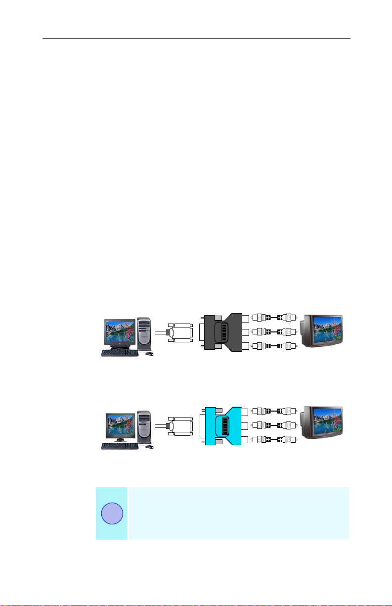
4 Plug the appropriate ATI HDTV Component Video
Adapter into the VGA connector or the DVI-I connector on
your RADEON Series card, and tighten the thumbscrews.
5 Using the appropriate cables, connect the ATI HDTV
Component Video Adapter’s outputs to your HDTV’ s video
inputs.
VGA or DVI-I
Connector on
RADEON 8500
Family Card
DVI-I Connector on
RADEON 9700/9500
(see table on page 3)
or
Series card
OEC
123456
VGA to YPbPr
or
DVI-I to YPbPr
Input and output cable lengths
should not exceed 50 feet (15m)
• Y = Green
•Pb= Blue
•Pr= Red
6 Turn on your component input device, and then set it to
YPbPr input (see your HDTV or component input device
manual for further instructions).
7 Turn on your PC. Your TV will not display anything until
Windows starts; this may take several minutes.
To return to your CRT monitor display, shut down your
computer, re-connect the CRT monitor, and then restart
your computer.
PrPbY
HDTV Video Inputs
Page 11

Using Your ATI HDTV Component Video Adapter 7
CHAPTER 3
Using Your A TI HDTV Component Video Adapter
Use the HDTV Component Video Adapter to watch DVD
movies and play video games on your High Definition
Television.
Copy-protected DVDs restrict playback to 480i and
i
480p modes.
For maximum performance when you watch DVD movies or
play computer games on your HDTV, you should find the mode
and screen resolution that provide the best result on your TV,
and use those settings exclusively.
Windows® Control Panel Settings
Use the Windows Control Panel settings to choose the
resolution and HDTV display mode.
To change settings using the Windows Control Panel
1 Click the Windows Start button, point at Settings, and then
click Control Panel.
2 Double-click the Display icon, click the Settings tab, and
use the Screen Area slider to select the resolution you
want.
Note: If the resolution you select is not related to a timing,
the system will reduce the resolution to the closest
supported timing.
3 Click the Advanced... button, then click the Displays tab.
4 Click the YPbPr tab.
Page 12

8 Using Your ATI HDTV Component Video Adapter
The HDTV settings page opens. The settings you selected
via the DIP switches are checked in Dongle Settings. (See
Setting the DIP Switches on page 5.)
To override the DIP switch settings, check the modes you
want in the Custom Settings buttons.
5 Click OK.
6 Click the Advanced... button,
7 Click the Adapter tab, then click the List All Modes...
button.
List All Modes is only available in Windows 2000 and
Windows XP. It is not available in Windows 98 / 98SE, or
Windows ME.
8 Click 640 x 480.
9 For Interlaced mode, click 30Hz or 60Hz.
YPbPr is only available with the 30Hz or 60HZ settings.
Windows XP does not enable 640 x 480 screen
resolution by default. To set 640 x 480 resolutio n,
right-click your desktop, click Properties, click the
Settings tab, click the Advanced button, click the
i
Adapter tab, click List all modes, then select
640 x 480.
• 60Hz = Progressive.
• 30Hz = Interlaced
If you experience problems, please see Tr oubleshooting Tips on
page 9.
Page 13

CHAPTER 4
T roubleshooting
This chapter contains troubleshooting tips for your Component
Video Adapter. The following tips may help if you experience
problems. Please contact your dealer for more advanced
troubleshooting information.
T roubleshooting Tip s
Problem Possible Solution
Troubleshooting 9
The colors on my
TV display are not
correct
There is no display
on my TV
DVDs will not play
in 720p or 1080i
modes
I can’t see the
entire display
The display is tilted Consult your HDTV user’s manual.
My CRT display is
green
Ensure that the connections between the
Component Video Adapter and your HDTV are
correct (Y=Green, Pb=Blue, Pr=Red). See the
illustration on page 6.
Your TV will not display anything until Windows
starts; this may take several minutes.
• Set your TV to YPbPr input.
• Ensure that the HDTV Component Video Adapter
is properly connected, then restart your computer.
• Ensure that the drivers in the ATI HTDV
Component Video Adapter Kit have been installed.
Copy-protected DVDs restrict playback to 480i and
480p modes.
If your component input device supports it, try 720p
mode.
Your system is in component output mode. Restart
your computer with the CRT monitor connected.
Page 14

10 Troubleshooting
Page 15

Index
Symbols
"Built by ATI" products 4
A
Adapter
connecting
Aspect ratio
C
Copy protection 7, 9
D
DIP switches
setting
setting aspect ratio
setting modes
G
Getting started 1
H
HDTV kit contents 2
I
Installing your ATI HDTV
Component Video Adapter
3
5
3
5
5
System requirements
T
Troubleshooting 9
U
Using your ATI HDTV Component
Video Adapter
V
Viewing mode
selecting
W
Warranty 2
Windows control panel settings
Windows XP, Windows 2000,
Windows 98 / 98SE, Windows ME
3
2
7
7
8
4
M
Modes 5
S
Setting the DIP switches 5
Setting up your ATI HDTV
Component Video Adapter
Software
installing
3
3
11
Page 16

12
Printed in Canada11 7-70104-30
 Loading...