

Page 1
O & M Manual
C12-17
Combustible Gas Transmitter
Home Office European Office
Analytical Technology, Inc. ATI (UK) Limited
6 Iron Bridge Drive Unit 1 & 2 Gatehead Business Park
Collegeville, PA 19426 Delph New Road, Delph
Phone: 800-959-0299 Saddleworth OL3 5DE
610-917-0991 Phone: +44 (0)1457-873-318
Fax: 610-917-0992 Fax: + 44 (0)1457-874-468
Email: sales@analyticaltechnology.com Email: sales@atiuk.com
Fax: 610-917-0992 Fax: + 44 (0)1457-874-468
Web: www.Analyticaltechnology.com
Page 2

C12-17 Combustible Gas Transmitter
TABLE OF CONTENTS
INTRODUCTION ..................................................................................................................................... 4
SPECIFICATIONS .................................................................................................................................... 5
INSTALLATION ...................................................................................................................................... 6
SENSOR LOCATION ................................................................................................................ 7
INTERFERENCES ..................................................................................................................... 7
ELECTRICAL CONNECTIONS - TRANSMITTER ................................................................ 8
ELECTRICAL CONNECTIONS - SENSOR ............................................................................. 9
DUAL CONDULET SYSTEM ................................................................................................... 10
OPERATION ............................................................................................................................................. 11
CALIBRATION .......................................................................................................................... 11
TRANSMITTER ZERO .............................................................................................................. 12
TRANSMITTER SPAN .............................................................................................................. 13
TRANSMITTER FAULT INDICATION ................................................................................... 13
CALIBRATION FOR OTHER COMBUSTIBLE GASES ........................................................ 14
SENSOR RESPONSE TEST ...................................................................................................... 15
SENSOR REPLACEMENT ........................................................................................................ 15
DISPLAY & RELAY OPTION................................................................................................................. 16
ALARM ADJUSTMENT ........................................................................................................... 18
TROUBLE FUNCTION ............................................................................................................. 18
C12-17 TRANSMITTER W/O DISPLAY SPARE PARTS LIST ............................................................ 19
C12-17 TRANSMITTER WITH DISPLAY SPARE PARTS LIST ......................................................... 20
TABLE OF FIGURES
FIGURE 1 - TYPICAL SYSTEM DIAGRAM (ATI-0145) ............................................................................... 4
FIGURE 2 - COMBUSTIBLE GAS SENSOR/TRANSMITTER DIMENSIONS (ATI-046) ............................ 6
FIGURE 3 - TRANSMITTER CUSTOMER CONNECTIONS (ATI-0237) .................................................... 8
FIGURE 4 - SENSOR CONNECTIONS TO TRANSMITTER (ATI-0144) .................................................... 9
FIGURE 5 - DUAL CONDULET CONNECTIONS (ATI-0579) ................................................................... 10
FIGURE 6 - DUAL CONDULET TYPICAL INSTALLATION ....................................................................... 10
FIGURE 7 - SENSOR/TRANSMITTER CONNECTORS, CONTROLS AND TEST POINTS (ATI-0143) . 12
FIGURE 8 - ENCLOSURE WITH DISPLAY DIMENSIONAL DRAWING (ATI-0569) ................................ 16
FIGURE 9 - TRANSMITTER WITH DISPLAY CUSTOMER CONNECTIONS (ATI-0570) ........................ 17
FIGURE 10 - STANDARD COMBUSTIBLE TRANSMITTER ECPLODED VIEW (ATI-0146) ................... 19
FIGURE 11 - STANDARD COMBUSTIBLE TRANSMITTER EXPLODED VIEW (ATI-0571) ................... 20
3
O&M Manual
Rev-D
Page 3
C12-17 Combustible Gas Transmitter
INTRODUCTION
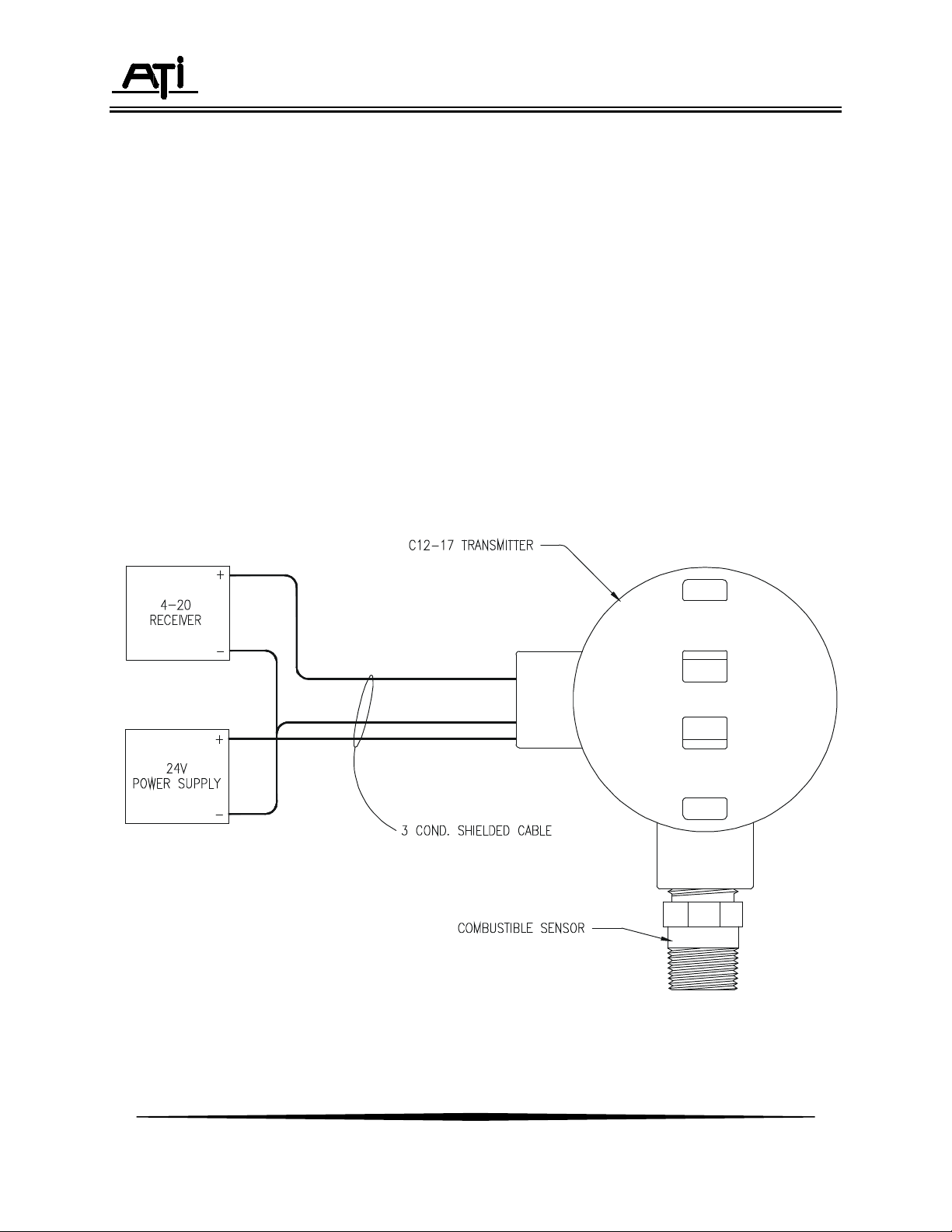
Series C12-17 sensor/transmitters combine catalytic bead type gas sensors and an electronic
amplifier that transmits gas concentration using a standard 4-20 mA signal. They are designed to
continuously monitor combustible gas concentrations in ambient air near process tanks or piping, or in
enclosed spaces where combustible gases may accumulate. C12-17 transmitters are available in two
versions, one containing an integral display and single alarm relay, and a second that is a simple “blind
transmitter” with no display or alarm functions.
Gas sensors are housed in a corrosion resistant stainless steel shell with a sintered metal flame
arrestor isolating the sensing elements from the ambient air. A 3/4" NPT thread at the back of the sensor
mates with the threaded entry on the explosion-proof transmitter enclosure. Series C12-17 sensor
transmitters are designed for use in Class 1, Division 1, Groups A, B, C, or D locations.
A typical installation for the C12-17 is shown in Figure 1 below.
Figure 1 - Typical System Diagram (ATI-0145)
O&M Manual
Rev-D
4
Page 4

C12-17 Combustible Gas Transmitter
SPECIFICATIONS
Range: 0-100% LEL (Lower Explosive Limit) Standard
0-50% LEL Optional
Response Time (T90) 10 Seconds
Sensitivity: 1% LEL
Zero Drift: < 2%/Month
Power: 10-28 VDC, 24 VDC at 100mA nominal
Output: 4-20 mA DC, 200 ohms maximum load at 12 VDC
800 ohms maximum load at 24 VDC
1000 ohms maximum load at 28 VDC
Display: Optional 2 ½ digit LCD
Alarm: Single setpoint or Trouble with SPDT, 1A, 125VAC; 1A, 30VDC alarm relay
Temperature Limits: -40° to + 70° C.
Sensor Materials: 316 Stainless Steel
Enclosure (Blind): Galvanized Cast Iron for blind transmitter
Area Classification: NEC Class 1, Division 1, Groups B, C, & D
Enclosure (for Display): Extruded Aluminum with glass window
Area Classification: NEC Class 1, Division 1, Groups A, B, C, & D
Connections: 3 wire, 20 AWG, 500 feet max. (150 m.)
Sensor Cable Length: Maximum 50 feet for separation between sensor and transmitter
Weight: 3 lbs. (1.4 Kg.)
O&M Manual
Rev-D
5
Page 5
C12-17 Combustible Gas Transmitter
INSTALLATION
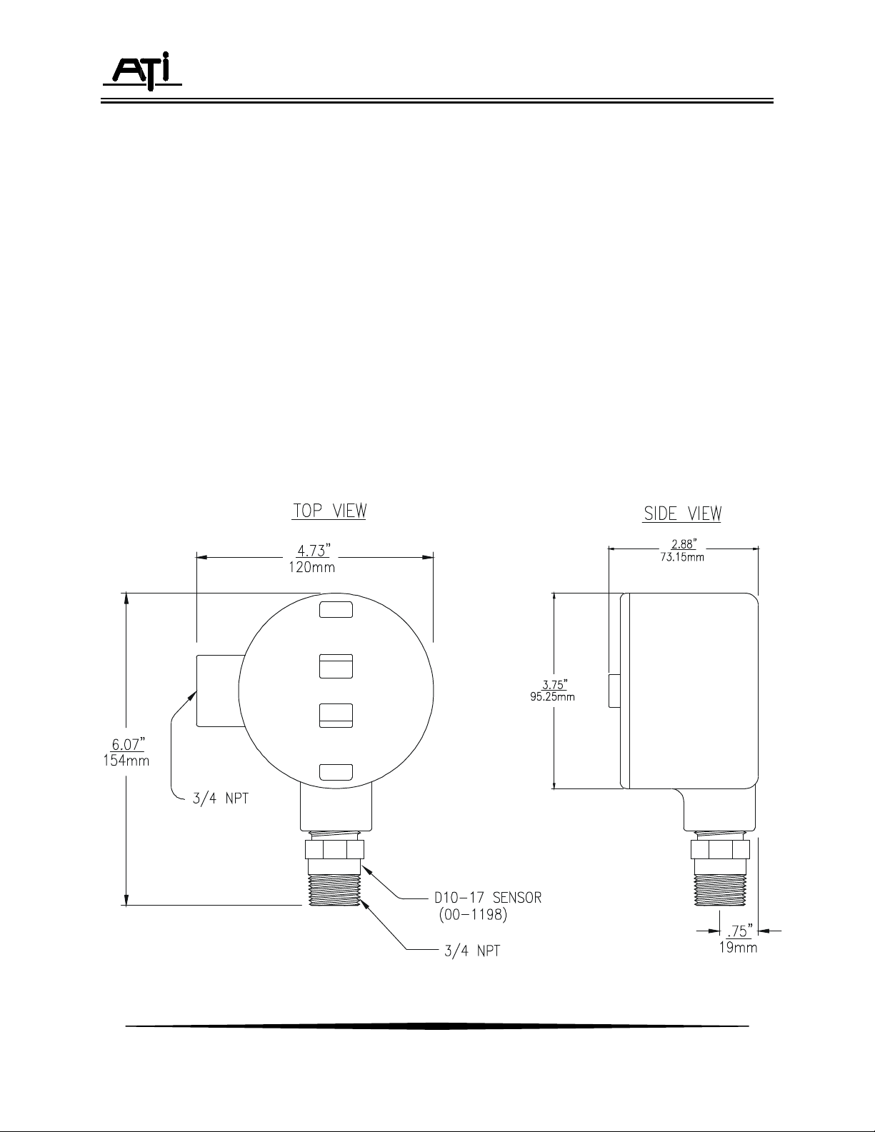
Combustible gas sensor/transmitters are explosion-proof assemblies that are normally mounted
directly to suitable explosion-proof conduit. To maintain the explosion-proof integrity of the transmitter, a
suitable cable entry seal must be used in accordance with the applicable electrical code.
Sensor/transmitters should be mounted with the sensor facing down as shown in Figure 2.
NOTE: Gas sensors are shipped with a protective plastic cap over the end. This cap should be left in
place to avoid damage to the sensor during installation. If the detection system is to be activated within a
few days of installation, the cap should be removed when installation is complete. Otherwise, leave the
cap in place until the system is to be placed in service. Be sure to leave the protective cap on the
sensor if painting is to be done in the area of the sensor.
Series C12-17 transmitters require connection to a DC power supply and connection of the 4-20
mA output to a receiving device such as a computer, recorder, or data logger. A 3-conductor cable may
be used for this purpose and is made at the terminals marked TB1 on Figure 3. Transmitters with the
optional display and relay may use a 2-wire connection if only the local relay is to be used. If the 4-20 mA
output is to be used, a 3-wire connection is needed.
Figure 2 - Combustible Gas Sensor/Transmitter Dimensions (ATI-046)
6
O&M Manual
Rev-D
Page 6

C12-17 Combustible Gas Transmitter
SENSOR LOCATION
Combustible gas sensors are used to detect a variety of gases or vapors. The proper sensor
location will depend on what type of gas is expected. For gases that are lighter than air, such as
methane, sensors should be located near the ceiling. For gases that are heavier than air, such as
butane, sensors should be mounted near the floor. If the gas or vapor has a density near that of air,
locate the sensor about 5 feet off the floor in enclosed areas. Gas sensors mounted outdoors should be
located near anticipated leak sources (valves, flanges, compressors, etc.) and the location will depend on
normal wind patterns and anticipated employee activity areas.
The following are a few common combustible gases, along with their relative density (air = 1.00).
Densities less than one indicate gases that are lighter than air while those with densities greater than one
are heavier than air. Combustible vapors from most solvents, such an Benzene, n-Hexane, Methanol,
Ethanol, and MEK, are heavier than air and will tend to accumulate near the floor in enclosed spaces with
little air movement.
Methane 0.55
Butane 2.11
Propane 1.55
Hydrogen 0.07
Ammonia 0.60
INTERFERENCES
Combustible gas sensors contain two heated elements. One of these elements is active, and will
allow combustible gases or vapors to burn on its catalytic surface. The other is passive, and does not
react to gases. These two elements form two legs of a Wheatstone bridge measuring circuit. When
combustible gas contacts the sensor, the active element burns this gas and the temperature of this
element increases, changing its resistance. The transmitter measures the imbalance in the bridge circuit
and transmits the data to the receiver for display and alarming purposes.
Combustible sensors are adversely affected by a few compounds that may be present in a given
application. Probably the worst of these are silicone vapors from silicon based lubricants or sealants.
High silicon vapor concentrations can cause complete loss of sensitivity in as little as a few hours. These
sensors should not be used where silicon vapors are normally present, and sensors should be protected
from these vapors if such compounds are in use temporarily.
Lead compounds and high levels of hydrogen sulfide can also cause degradation of combustible
sensors. While lead vapors are not commonly encountered, they can also cause complete sensor failure
if encountered. Hydrogen sulfide will cause reduced sensitivity over the first few weeks of exposure, but
then will level out. The effect of hydrogen sulfide can normally be compensated for by re-calibration after
the first few weeks of use.
O&M Manual
Rev-D
7
Page 7
C12-17 Combustible Gas Transmitter
Important: If the loop output is not used to
ELECTRICAL CONNECTIONS - TRANSMITTER
External connections to the C12-17 transmitter can be made using 3 conductor cable. A 3conductor cable uses a single conductor for the common of both the power supply and the output signal.
Figure 3 shows typical connections to a power supply and a panel indicator running off the 4-20 mA
signal from the C12-17 transmitter.
ZERO
LEL Transmitter
SPAN
drive an external device, jump the
LOOP terminal to the COM
terminal
Figure 3 - Transmitter Customer Connections (ATI-0237)
O&M Manual
Rev-D
8
Page 8

C12-17 Combustible Gas Transmitter
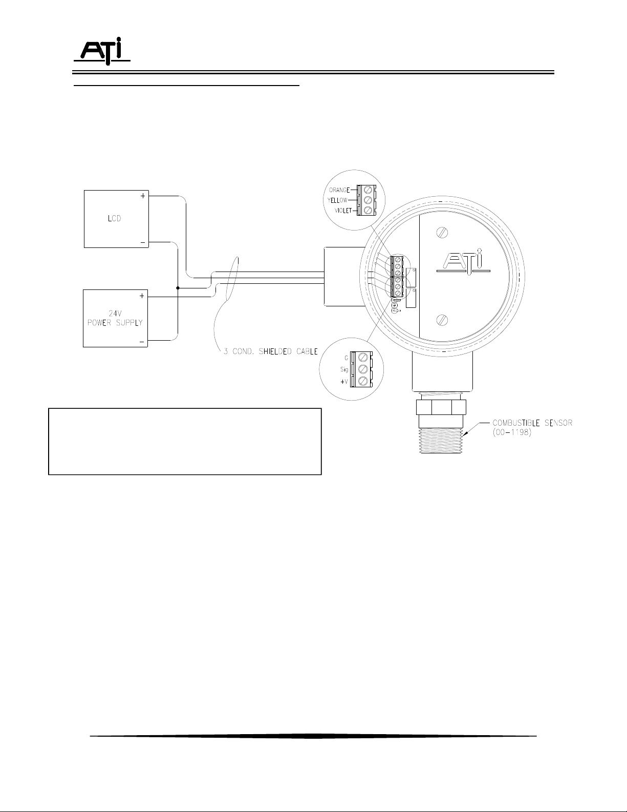
ELECTRICAL CONNECTIONS - SENSOR
Standard transmitters supplied with the sensor close coupled to the transmitter enclosure are
factory wired as shown below. However, sensors can be supplied with up to 25 feet of cable for remote
mounting. The wiring diagram for the extended cable version is also shown below. Extended cables
should always be installed in suitable explosion-proof flexible conduit where required by the electrical
code.
Figure 4 - Sensor Connections to Transmitter (ATI-0144)
O&M Manual
Rev-D
9
Page 9

C12-17 Combustible Gas Transmitter
CEILING
DUAL CONDULET SYSTEM
For some indoor applications, it is more convenient to mount the sensor toward the ceiling of the
room while keeping the transmitter electronics down at a convenient elevation for making calibration
adjustments. ATI's dual condulet system is designed for this purpose, and the interconnecting wiring is
shown below. A special remote calibration adapter can be used with this system to allow gas to be fed
from a point near the transmitter as shown in Figure 6.
Figure 5 - Dual Condulet Connections (ATI-0579)
CONDUIT CLAMPS (AS REQUIRED)
DISTANCE AS REQUIRED
BY APPLICATION
COMBUSTIBLE
TRANSMITTER
SIDE VIEW
5 FT.
TO
RECEIVER
FRONT VIEW
1/4" DIA. PVC FLEX TUBING - CAL GAS FEED
SECURE TUBING TO CONDUIT WITH TIE WRAPS
TO SENSOR
NOTE: EXPLOSION-PROOF CONDUIT
WITH SEALS AS REQUIRED BY LOCAL
ELECTRICAL CODE.
EXPLOSION-PROOF JUNCTION BOX
(ATI# 00-0263)
COMBUSTIBLE GAS SENSOR
REMOTE CALIBRATION ADAPTOR
Figure 6 - Dual Condulet Typical Installation
10
O&M Manual
Rev-D
Page 10

C12-17 Combustible Gas Transmitter
OPERATION
Once installation is complete, the C12-17 combustible gas transmitter is ready for operation.
After verifying that electrical connections have been made properly, put the transmitter into operation by
simply applying DC power. As soon as power is applied, the unit will begin to stabilize. Once stabilized,
alarm system inhibit can be turned off, and the system will be in normal operation.
Note: The output of the transmitter will go to a high value when power is first applied. Alarm
devices should be inhibited at this time so that alarm systems are not activated. The
output will stabilize at 4 mA within about 10 minutes.
CALIBRATION
Combustible gas sensor/transmitters are factory calibrated for a standard range of 0-100% LEL
Methane, using methane gas as the calibration standard. However, combustible gas sensors do not
respond exactly the same to every combustible gas, and the percent of each gas that represents 100%
LEL also differs for each gas. While methane gas standards can always be used for calibration, the value
that the transmitter is adjusted to will vary depending on what type of gas the system is meant to detect.
Calibration of a combustible gas sensor/transmitter requires a digital voltmeter (DVM), a source of
calibration gas, and a calibration adapter for the sensor. Calibration gas can be obtained in convenient
disposable cylinders from specialty gas suppliers such as Scott Specialty Gases, Alphagaz, or Matheson
Gas Products. Complete calibration kits may also be purchased from ATI. These kits contain one
methane gas standard (1% methane in air, which is 20% LEL) in a disposable cylinder, a bottle of zero
air, a cylinder regulator, and a calibration adapter.
Prior to calibration, remove the cover from the sensor/transmitter enclosure and connect a DVM
to the test points (TP) shown in Figure 7. If the receiver for the system is near enough to easily see, you
may use the digital display on the receiver instead of a DVM on the test points. The test points will
provide a 40-200 mv. signal proportional to transmitter range. For a standard 0-100% LEL unit, 0% is 40
mv. and 100% is 200 mv.
O&M Manual
Rev-D
11
Page 11

C12-17 Combustible Gas Transmitter
LEL Transmitter
S
P
A
N
Z
E
R
O
Figure 7 - Sensor/Transmitter Connectors, Controls and Test Points (ATI-0143)
TRANSMITTER ZERO
The transmitter zero is adjusted with the sensor exposed to air that contains no combustible gas.
Generally, the easiest method of zeroing the transmitter is to make the adjustment when you know that
the area is free of combustibles. Because it is normally necessary to check the area with a portable
combustible detector prior to removing the cover from the transmitter, the absence of an combustible
gases or vapors can be verified fairly easily.
The transmitter can also be set to zero using "zero air" available in cylinders. Zero air cylinders
and regulators are available from ATI or from specialty gas suppliers. Connect the zero air cylinder to the
calibration adapter and adjust gas flow to 500 cc/min. When the DVM stabilizes near 40mV, adjust the
zero potentiometer until the DVM reads 40 ± 0.5 mv.
NOTE: If using the ATI receiver display when adjusting the transmitter zero, place the receiver in
the "Inhibit" mode. When in the inhibit mode, the blanking around zero is disabled so that
the zero can be set accurately.
12
O&M Manual
Rev-D
Page 12

C12-17 Combustible Gas Transmitter
TRANSMITTER SPAN
The span setting for a combustible gas sensor/transmitter will depend on the gas or vapor for
which the unit will be mainly used. To calibrate the system for applications where methane in the main
combustible to be expected, connect tubing from your span gas cylinder (1% Methane) to the calibration
adapter inlet. Turn on the gas flow and adjust to approximately 500 cc/min. (ATI calibration kits contain
fixed flow regulators that automatically provide 500 cc/min. flow). The reading on the DVM attached to
the transmitter test points will immediately start to increase. Allow the gas to flow to the sensor for 2-3
minutes and observe the reading on the DVM. The reading should be relatively stable ± 0.5 mv. Use the
span potentiometer to adjust the DVM to 72 mv. This adjustment assumes the use of 1% methane gas
standards, which are the equivalent of 20% LEL. If using another methane concentration, calculate the
voltage setting as follows: (v/o = Volume Percent)
V = 40 mV + [160 mV X (Span Gas Concentration in V/O ÷ 5 V/O )]
As an example, if your span gas cylinder is marked with a concentration of 2.5% Methane, the
calculation would be:
V = 40 mV + [160 mV X (2.5 V/O ÷ 5 V/O)] = 120 mV
When the span has been set, turn off the span gas flow and remove the calibration adapter from
the sensor. Place the lid back on the transmitter enclosure and tighten the cover to insure the enclosure
remains watertight. If the ATI receiver alarm relays were inhibited prior to calibration, press the A/R
switch to return the system to normal operation.
TRANSMITTER FAULT INDICATION
The C12-17 combustible gas transmitter is designed to detect certain fault conditions in the
sensor and transmitter and to indicate the fault conditions by driving the 4-20 mA output to below 2 mA.
Receiving instruments that can identify this condition and provide a visual indication of the fault will
provide added security for your gas detection system. When the C12 signal is used as an input to a PLC
or computer system, the system should be programmed to recognize a 2 mA output as a fault condition
for the transmitter.
The below 2 mA fault condition will be generated under the following conditions:
One of the sensor leads is not connected at the terminal block.
A sensor wire has broken in the interconnect wiring of a dual condulet installation.
The combustible sensing element has failed.
O&M Manual
Rev-D
13
Page 13

C12-17 Combustible Gas Transmitter
GAS
VOLTAGE, mV
% LEL
CALIBRATION FOR OTHER COMBUSTIBLE GASES
As previously mentioned, a combustible gas sensor has a slightly different response to each
combustible gas or vapor. In addition, the LEL (Lower Explosive Limit) represents different percent
concentrations for different gases. For instance, the LEL for methane is 5% by volume while the LEL for
butane is 1.9% by volume. Because of these factors, a combustible transmitter must be adjusted
differently if the system is meant to detect a gas or vapor other than methane.
A 1% methane gas standard may still be used for calibration of combustible transmitters when
used for other gases. However, the voltage that you set at the transmitter test point will be different for
each gas. Table 1 provides the voltage setting for various gases, and the corresponding percent LEL
reading for each.
TABLE 1
Methane 72 20
Propane 98 36
n-Butane 96 35
n-Pentane 109 43
n-Hexane 127 56
Hydrogen 82 26
Methanol 77 23
Ethanol 83 27
Isopropyl Alcohol 109 43
Acetone 102 39
Methyl Ethyl Ketone 118 49
Benzene 120 50
Toluene 120 50
Acetylene 98 36
Di-ethyl Ether 109 43
Ammonia 67 16
n-Heptane 125 53
14
O&M Manual
Rev-D
Page 14

C12-17 Combustible Gas Transmitter
SENSOR RESPONSE TEST
While zero and span adjustments are required only periodically, gas sensors should be checked
regularly for proper response. The response check can be done quickly by simply aiming the outlet tube
from the span gas cylinder at the face of the sensor and turning on the gas flow for 10-20 seconds. The
sensor should begin to respond within 5 seconds.
To observe the response at the transmitter, it is necessary to connect a DVM to the test points
indicated in Figure 7. If the receiver is nearby, you may simply observe the digital display on the receiver.
If the sensor does not respond, it should be replaced.
SENSOR REPLACEMENT
Combustible gas sensors used in the C12 are warranted for 12 months and generally last 5 years
or more in the absence of poisoning agents. When sensor replacement is required, it can be done easily
and quickly. Open the transmitter and remove the sensor cable from the sensor terminal block on the
transmitter module. Unscrew the sensor from the explosion-proof transmitter housing using a wrench on
the hex provided on the sensor. Screw in the replacement sensor.
Connect the new sensor to the terminal block (figure 3), on the transmitter board and replace the
transmitter cover. After a new sensor has been connected, allow 4 hours for the new sensor to
completely stabilize. Then perform a zero and span calibration as described on pages 11 through 13.
O&M Manual
Rev-D
15
Page 15

C12-17 Combustible Gas Transmitter
DISPLAY & RELAY OPTION
C12-17 transmitters supplied with the display and relay option offer additional features that make
operation and calibration somewhat simpler. In addition, the relay allows for local alarm of a high gas
condition without the need for wiring back and forth to a remote alarm module.
In normal operation, this version of the C12-17 will continuously display %LEL on the integral
liquid crystal display. This display can be used for zeroing and calibration of the transmitter, eliminating
the need for a separate DVM as described in the calibration section of this manual.
Figure 8 - Enclosure with Display Dimensional Drawing (ATI-0569)
16
O&M Manual
Rev-D
Page 16

C12-17 Combustible Gas Transmitter
Figure 9 - Transmitter with Display Customer Connections (ATI-0570)
17
O&M Manual
Rev-D
Page 17

C12-17 Combustible Gas Transmitter
ALARM ADJUSTMENT
Units supplied with the optional display contain a single alarm setpoint and relay which may be used for
local alarm functions. The SPDT internal relay is ideal for simple applications where only a local lamp or horn is
needed when elevated gas levels are detected.
The alarm setpoint is adjusted using the calibrated dial on the front of the transmitter. The dial is marked 0100 corresponding to 0-100% LEL. Note that the alarm setpoint cannot be set for a value below 5%. Simply adjust
the dial to the desired value and the relay will actuate when the combustible gas level reaches that point. When the
relay is activated, a decimal point to the left of the concentration display will indicate that the relay is latched.
The relay is a latching relay and must be reset manually. Reset is done using a magnet through the window
of the display. A magnetic screwdriver is supplied with the transmitter for this purpose. If the relay activates and
the gas concentration returns to normal, simply hold the magnet on the end of the screwdriver against the yellow dot
in the window. The relay will immediately return to a deenergized state. Note that the relay will not reset until the
gas concentration is below the setpoint.
TROUBLE FUNCTION
If the internal relay is not to be used for gas concentration alarming, its function can be changed to a trouble
relay to provide local indication of a fault condition. If the setpoint is adjusted to “0”, the relay will automatically
become a trouble relay. If any of the fault conditions described on page 13 occur, the relay will activate. The relay
is non-latching and will reset if the fault condition clears.
When transmitter trouble is detected, the LCD display will indicate a “-1” value and the current loop will
go to 2 mA. Transmitter operation will return to normal when the trouble condition is corrected.
O&M Manual
Rev-D
18
Page 18

C12-17 Combustible Gas Transmitter
Part Number
Description
C12-17 TRANSMITTER W/O DISPLAY
SPARE PARTS LIST
ZERO
LEL Transmitter
SPAN
Figure 10 - Standard Combustible Transmitter Ecploded View (ATI-0146)
00-1256 C12-17 Combustible Transmitter Module
80-0017 Explosion-proof Enclosure
00-1198 D10-17 Combustible Sensor Assembly
92-0043 10-32 x 1¼” PHMS, S.S. Phillips
92-0044 Fiber Washer
45-0046 Splash guard
00-0258 Calibration Adapter
00-0261 Remote Calibration Adapter/Rain Shield
19
O&M Manual
Rev-D
Page 19

C12-17 Combustible Gas Transmitter
Part Number
Description
C12-17 TRANSMITTER WITH DISPLAY
SPARE PARTS LIST
Figure 11 - Standard Combustible Transmitter Exploded View (ATI-0571)
00-1258 C12-17 Combustible Transmitter Module with Display
80-0074 Explosion-proof Enclosure for Display Module
00-1198 D10-17 Combustible Sensor Assembly
92-0043 10-32 x 1¼” PHMS, S.S. Phillips
92-0044 Fiber Washer
45-0046 Splash Guard
00-0258 Calibration Adapter
00-0261 Remote Calibration Adapter/Rain Shield
O&M Manual
Rev-D
20
Page 20

PRODUCT WARRANTY
Analytical Technology, Inc. (Manufacturer) warrants to the Customer that if any
part(s) of the Manufacturer's equipment proves to be defective in materials or
workmanship within the earlier of 18 months of the date of shipment or 12 months of the
date of start-up, such defective parts will be repaired or replaced free of charge.
Inspection and repairs to products thought to be defective within the warranty period will
be completed at the Manufacturer's facilities in Collegeville, PA. Products on which
warranty repairs are required shall be shipped freight prepaid to the Manufacturer. The
product(s) will be returned freight prepaid and allowed if it is determined by the
manufacturer that the part(s) failed due to defective materials or workmanship.
This warranty does not cover consumable items, batteries, or wear items subject
to periodic replacement including lamps and fuses.
Gas sensors carry a 12 months from date of shipment warranty and are subject
to inspection for evidence of misuse, abuse, alteration, improper storage, or extended
exposure to excessive gas concentrations. Should inspection indicate that sensors
have failed due to any of the above, the warranty shall not apply.
The Manufacturer assumes no liability for consequential damages of any kind,
and the buyer by acceptance of this equipment will assume all liability for the
consequences of its use or misuse by the Customer, his employees, or others. A defect
within the meaning of this warranty is any part of any piece of a Manufacturer's product
which shall, when such part is capable of being renewed, repaired, or replaced, operate
to condemn such piece of equipment.
This warranty is in lieu of all other warranties ( including without limiting the
generality of the foregoing warranties of merchantability and fitness for a particular
purpose), guarantees, obligations or liabilities expressed or implied by the Manufacturer
or its representatives and by statute or rule of law.
This warranty is void if the Manufacturer's product(s) has been subject to misuse
or abuse, or has not been operated or stored in accordance with instructions, or if the
serial number has been removed.
Analytical Technology, Inc. makes no other warranty expressed or implied except
as stated above.
Page 21

WATER QUALITY MONITORS
Dissolved Oxygen
Free Chlorine
Combined Chlorine
Total Chlorine
Residual Chlorine Dioxide
Potassium Permanganate
Dissolved Ozone
pH/ORP
Conductivity
Hydrogen Peroxide
Peracetic Acid
Dissolved Sulfide
Residual Sulfite
Fluoride
Dissolved Ammonia
Turbidity
Suspended Solids
Sludge Blanket Level
MetriNet Distribution Monitor
GAS DETECTION PRODUCTS
NH3 Ammonia
CO Carbon Monoxide
H2 Hydrogen
NO Nitric Oxide
O2 Oxygen
CO Cl2 Phosgene
Br2 Bromine
Cl2 Chlorine
ClO2 Chlorine Dioxide
F2 Fluorine
I2 Iodine
HX Acid Gases
C2H4O Ethylene Oxide
C2H6O Alcohol
O3 Ozone
CH4 Methane
(Combustible Gas)
H2O2 Hydrogen Peroxide
HCl Hydrogen Chloride
HCN Hydrogen Cyanide
HF Hydrogen Fluoride
H2S Hydrogen Sulfide
NO2 Nitrogen Dioxide
NOx Oxides of Nitrogen
SO2 Sulfur Dioxide
H2Se Hydrogen Selenide
B2H6 Diborane
GeH4 Germane
AsH3 Arsine
PH3 Phosphine
SiH4 Silane
HCHO Formaldehyde
C2H4O3 Peracetic Acid
DMA Dimethylamine
 Loading...