

Page 1
Manual, Axia80 EtherCAT F/T Sensor
Document #: 9610-05-Axia80 EtherCAT
Engineered Products for Robotic Productivity
Pinnacle Park • 1031 Goodworth Drive • Apex, NC 27539 USA • Tel: +1.919.772.0115 • Fax: +1.919.772.8259 • www.ati-ia.com • Email: info@ati-ia.com
Page 2

Manual, F/T Sensor, Axia80 EtherCAT
Document #9610-05-Axia80 EtherCAT-09
Foreword
Information contained in this document is the property of ATI Industrial Automation, Inc. and shall not be reproduced in
whole or in part without prior written approval of ATI Industrial Automation, Inc. The information herein is subject to
change without notice and should not be construed as a commitment of ATI Industrial Automation, Inc. This manual is
periodically revised to reect and incorporate changes made to the F/T system.
ATI Industrial Automation, Inc. assumes no responsibility for any errors or omissions in this document.
Copyright © by ATI Industrial Automation, Inc., Apex, North Carolina USA. All Rights Reserved. Published in the USA.
In consideration that ATI Industrial Automation, Inc. (ATI) products are intended for use with robotic and/or automated
machines, ATI does not recommend the use of its products for applications wherein failure or malfunction of an ATI
component or system threatens life or makes injury probable. Anyone who uses or incorporates ATI components within
any potentially life-threatening system must obtain ATI’s prior consent based upon assurance to ATI that a malfunction
of ATI’s component does not pose direct or indirect threat of injury or death, and (even if such consent is given) shall
indemnify ATI from any claim, loss, liability, and related expenses arising from any injury or death resulting from use of
ATI components.
All trademarks belong to their respective owners. EtherCAT® is a registered trademark and patented technology, licensed
by Beckhoff Automation GmbH, Germany.
Note
Please read the manual before calling customer service. Before calling, have the following
information available:
1. Serial number (e.g., FT01234)
2. Transducer model (e.g., Axia80, etc.)
3. Calibration (e.g., US-120-95, etc.)
4. Accurate and complete description of the question or problem
5. Computer and software information. Operating system, PC type, drivers, application
software, and other relevant information about your conguration.
If possible, be near the F/T system when calling.
How to Reach Us
Sale, Service and Information about ATI products:
A TI Industrial Automation
1031 Goodworth Drive
Apex, NC 27539 USA
www.ati-ia.com
Tel: 919.772.0115
Fax: 919.772.8259
E-mail: info@ati-ia.com
Technical support and questions:
Application Engineering
Tel: 919.772.0115, Option 2, Option 2
Fax: 919.772.8259
E-mail: ft_support@ati-ia.com
Pinnacle Park • 1031 Goodworth Drive • Apex, NC 27539 USA • Tel: +1.919.772.0115 • Fax: +1.919.772.8259 • www.ati-ia.com • Email: info@ati-ia.com
2
Page 3

Manual, F/T Sensor, Axia80 EtherCAT
Document #9610-05-Axia80 EtherCAT-09
Table of Contents
Foreword .......................................................................................................................................... 2
Glossary
........................................................................................................................................... 5
1. Safety ......................................................................................................................................... 7
1.1 ExplanationofNotications .........................................................................................................7
1.2 General Safety Guidelines ............................................................................................................7
1.3 Safety Precautions ........................................................................................................................8
2. Product Overview ..................................................................................................................... 9
2.1 LED Self-Test Sequence and Functions ....................................................................................10
2.1.1 LED Self-Test Sequence .................................................................................................. 10
2.1.2 EtherCAT Link/Activity LED ..............................................................................................10
2.1.3 Run LED ...........................................................................................................................10
2.1.4 Sensor Status LED ...........................................................................................................10
3. Installation ...............................................................................................................................11
3.1 Adapter Plates ............................................................................................................................. 11
3.2 Routing the Cable ........................................................................................................................13
3.3 Installing the Sensor to the Robot .............................................................................................14
3.4 Removing the Sensor from the Robot .......................................................................................15
3.5 Pin Assignment for the EtherCAT and Power Connection ...................................................... 16
3.5.1 Pin Assignment for the 6-pin M8 Male Connector on the Sensor .....................................16
3.5.2 Pin Assignment for the 8-Pin M12 Male Connector
on Cable P/N 9105-C-ZC22-ZC26-X ................................................................................16
3.5.3 Pin Assignment for Cable P/N 9105-C-ZC26-U-RJ45S-X, Branch 1, Unterminated End for
Power Connection ............................................................................................................17
3.5.4 Pin Assignment for Cable P/N 9105-C-ZC26-U-RJ45S-X, Branch 2, RJ45 Connection ..17
3.6 Accuracy Check Procedure ........................................................................................................18
4. Operation ................................................................................................................................ 19
4.1 Sensor Environment ...................................................................................................................19
4.2 Sample Rate .................................................................................................................................19
4.3 Low-pass Filter ............................................................................................................................19
Pinnacle Park • 1031 Goodworth Drive • Apex, NC 27539 USA • Tel: +1.919.772.0115 • Fax: +1.919.772.8259 • www.ati-ia.com • Email: info@ati-ia.com
3
Page 4

Manual, F/T Sensor, Axia80 EtherCAT
Document #9610-05-Axia80 EtherCAT-09
5. EtherCAT Bus Interface ......................................................................................................... 22
5.1 PDO Interface ...............................................................................................................................22
5.2 EtherCAT Dictionary Objects (SDO Data) ................................................................................22
5.2.1 Object 0x2021: Calibration ...............................................................................................22
5.2.2 Object 0x2080: Diagnostic Readings ...............................................................................24
5.2.3 Object 0x2090: Version ....................................................................................................25
5.2.4 Object 0x6000: Reading Data ..........................................................................................25
5.2.5 Object 0x6010: Status Code ............................................................................................26
5.2.6 Object 0x6020: Sample Counter ......................................................................................27
5.2.7 Object 0x6030: Gage Data ...............................................................................................27
5.2.8 Object 0x7010: Control Codes .........................................................................................28
5.3 Establishing Communication with the Axia80 EtherCAT Sensor ........................................... 29
6. Maintenance ............................................................................................................................ 29
6.1 Periodic Inspection .....................................................................................................................29
6.2 Periodic Calibrating ....................................................................................................................29
7. Troubleshooting .......................................... ........................................................................... 30
7.1 Errors with Force and Torque Readings ...................................................................................30
8. Specications ......................................................................................................................... 31
8.1 Storage and Operating Conditions ............................................................................................31
8.2 ElectricalSpecications .............................................................................................................31
8.3 Calibration Ranges ......................................................................................................................31
9. Drawings ................................................................................................................................. 32
10. Terms and Conditions of Sale ............................................................................................... 33
Pinnacle Park • 1031 Goodworth Drive • Apex, NC 27539 USA • Tel: +1.919.772.0115 • Fax: +1.919.772.8259 • www.ati-ia.com • Email: info@ati-ia.com
4
Page 5

Manual, F/T Sensor, Axia80 EtherCAT
Document #9610-05-Axia80 EtherCAT-09
Glossary
Term Denition
Accuracy See Measurement Uncertainty.
ADC Analog-to-digital converter.
Calibration
Calibration Certicate
CoE
Compound Loading Any load that is not purely in one axis.
Coordinate Frame See point of origin.
DINT A 32-bit data type representing a signed integer.
DoF Degrees of freedom. See six degrees of freedom.
EtherCAT An industrial automation eldbus.
FoE
Force The push or pull exerted on an object.
FS Full-Scale.
F/T Force/Torque.
F/T Transducer The device that converts force and torque into an electrical signal.
Fxy The resultant force vector comprised of components Fx and Fy.
Full-Scale Error
Hysteresis
IP60 Ingress protection rating “60” designates protection against dust.
ISR Interrupt service routine.
MAP
MAX. Single-Axis Overload
Measurement Uncertainty
Moment An object that receives a torque has a moment applied to that object.
Offset Compensation
Overload
PDO
The act of measuring a transducer’s raw response to loads and
creating data used in converting the response to forces and torques.
A statement that says the equipment measures correctly. These
statements mean the equipment has been tested against national
standards. The statements are produced as a result of calibration or
re-calibration.
CANopen over EtherCAT is the preferred embedded protocol for
conguring EtherCAT devices. Used within SDO to encode the
conguration data.
File access over EtherCAT, the preferred embedded protocol for
uploading new rmware to EtherCAT devices.
A measurement of sensing error. For example, if the calibrated
measurement range of a sensor is 100 Newtons and the sensor is
accurate to within 1 Newton, that sensor will have a Full-Scale Error of
1% (1% = 0.01 = 1 N / 100 N).
A source of measurement error caused by the residual effects of
previously applied loads.
The Mounting Adapter Plate (MAP) is the transducer plate that attaches
to the xed surface or robot arm.
The largest amount of load in a single axis (all other axes are unloaded)
that the transducer can withstand without damage.
The maximum expected error in measurements, as specied on the
calibration certicate.
Correction of errors that change the zero point of a transducer’s
readings.
The condition where more load is applied to the transducer. This will
result in saturation.
Process Data Object, a protocol for reading and writing real-time
process information cyclically.
Pinnacle Park • 1031 Goodworth Drive • Apex, NC 27539 USA • Tel: +1.919.772.0115 • Fax: +1.919.772.8259 • www.ati-ia.com • Email: info@ati-ia.com
5
Page 6

Manual, F/T Sensor, Axia80 EtherCAT
Document #9610-05-Axia80 EtherCAT-09
Term Denition
Point of Origin The point from which the transducer measures all forces and torques.
The way the continuously variable transducer signal is converted into
Quantization
discrete digital values. Usually used when describing the change from
one digital value to the next.
RAM Random access memory.
Torque applied that does not result in movement. For example, if a user
Reaction Torque
twists a screw or bolt but the fastener does not move. ATI transducers
sense reaction torque.
The periodic verication of measurement equipment, like transducers,
Re-Calibration
calipers, and voltmeters, to prove it still measures correctly. The
equipment may be adjusted if it doesn’t measure correctly.
Resolution
The smallest change in load that can be measured. This is usually
much smaller than accuracy.
Torque resulting in something moving. Generally this refers to the
Rotary Torque
torque on things like drive shafts. ATI transducers cannot sense
rotational torque.
Saturation
SDO
The condition where the transducer has a load or signal outside its
sensing range.
Service Data Object, a protocol for reading and writing conguration
information acyclically.
Six Degrees of Freedom Fx, Fy, Fz, Tx, Ty , and Tz.
SG Strain Gage.
STRING(8) A data type representing (8) characters, using (8) bytes.
STRING(30) A data type representing (30) characters, using (30) bytes.
TAP
Tool Adapter Plate (TAP) is the transducer surface that attaches to the
load to be measured.
Torque The measurement of force exerted on an object causing it to rotate.
Transducer
Transducer is the component that converts the sensed load into
electrical signals.
Txy The resultant torque vector comprised of components Tx and Ty.
UDINT A (32) bit data type representing an unsigned integer.
UINT A (16) bit data type representing an unsigned integer.
USINT An (8) bit data type representing an unsigned integer.
Pinnacle Park • 1031 Goodworth Drive • Apex, NC 27539 USA • Tel: +1.919.772.0115 • Fax: +1.919.772.8259 • www.ati-ia.com • Email: info@ati-ia.com
6
Page 7
Manual, F/T Sensor, Axia80 EtherCAT
Document #9610-05-Axia80 EtherCAT-09
1. Safety
The safety section describes general safety guidelines for the product(s), an explanation of the notications found
in this manual, and the safety precautions applicable to the product(s). More specic notications are embedded
within the sections of the manual where they apply.
1.1 ExplanationofNotications
The notications included here are specic to the product(s) covered by this manual. The user should heed
all notications from the robot manufacturer and/or the manufacturers of other components used in the
installation.
DANGER: Notication of information or instructions that if not followed will result in
death or serious injury. The notication provides information about the nature of the
hazardous situation, the consequences of not avoiding the hazard, and the method for
avoiding the situation.
WARNING: Notication of information or instructions that if not followed could result
in death or serious injury. The notication provides information about the nature of the
hazardous situation, the consequences of not avoiding the hazard, and the method for
avoiding the situation.
CAUTION: Notication of information or instructions that if not followed could result in
moderate injury or cause damage to equipment. The notication provides information
about the nature of the hazardous situation, the consequences of not avoiding the
hazard, and the method for avoiding the situation.
NOTICE: Notication of specic information or instructions about maintaining, operating,
installation, or setup of the product that if not followed could result in damage to equipment. The
notication can emphasize but is not limited to specic grease types, good operating practices,
or maintenance tips.
1.2 General Safety Guidelines
The customer should verify that the transducer selected is rated for maximum loads and torques expected
during operation. Because static forces are less than the dynamic forces from the acceleration or declaration
of the robot, be aware of the dynamic loads caused by the robot.
Pinnacle Park • 1031 Goodworth Drive • Apex, NC 27539 USA • Tel: +1.919.772.0115 • Fax: +1.919.772.8259 • www.ati-ia.com • Email: info@ati-ia.com
7
Page 8
Manual, F/T Sensor, Axia80 EtherCAT
Document #9610-05-Axia80 EtherCAT-09
1.3 Safety Precautions
WARNING: Performing maintenance or repair on the sensor, while circuits (e.g. power,
water, and air) are energized could result in serious injury. Discharge and verify all
energized circuits are de-energized in accordance with the customer’s safety practices
and policies.
CAUTION: Modifying or disassembly of the sensor could cause damage and void the
warranty. Use the supplied mounting adapter plate and the provided tool side mounting
bolt pattern to mount the sensor to the robot and customer tooling to the sensor. Refer
to Section 9—Drawings for more information.
CAUTION: Using fasteners that exceed the customer interface depth penetrates
the body of the sensor, damages the electronics, and voids the warranty. Refer to
Section 9—Drawings for more information.
CAUTION: Probing openings in the sensor causes damage to the instrumentation.
Avoid prying into openings of the transducer.
CAUTION: Do not overload the transducer. Exceeding the single-axis overload values
of the transducer, causes irreparable damage.
CAUTION: Do not contact the IP60 seal. Contacting the seal can cause the sensor to
malfunction.
CAUTION: The sensor should be protected from impact and shock loads that exceed
rated ranges during transport as the impacts can damage the sensor’s performance.
Refer to Section8—Specications for more information about rated ranges.
CAUTION: Avoid damage to the sensor from Electro-Static Discharge. Ensure proper
grounding procedures are followed when handling the sensor or cables connected to
the sensor. Failure to follow proper grounding procedures could damage the sensor.
Pinnacle Park • 1031 Goodworth Drive • Apex, NC 27539 USA • Tel: +1.919.772.0115 • Fax: +1.919.772.8259 • www.ati-ia.com • Email: info@ati-ia.com
8
Page 9
Manual, F/T Sensor, Axia80 EtherCAT
Document #9610-05-Axia80 EtherCAT-09
2. Product Overview
The Axia80 EtherCAT F/T sensor system measures (6) components of force and torque (Fx, Fy, Fz, Tx, Ty, Tz) and
streams data to customer devices that use EtherCAT eldbus. Refer to Section 5.1—PDO Interface.
The mounting side attaches to a mounting adapter plate, which mounts to the customer robot. The tool side attaches
to the customer tooling. Both the mounting and tool sides have a 71.12 mm bolt circle pattern with (6) M5 tapped
holes. Refer Section 9—Drawings for more information. The sensor is IP60 rated. A M8 6-pin male connector is for
power and EtherCAT. For the pin assignments, refer to Section 3.5—Pin Assignment for the EtherCAT and Power
Connection.
The Axia80 sensor provides the following features:
• Resolved force and torque data (refer to Section 5.1—PDO Interface)
• Set bias and clear bias
• Programmable low-pass ltering
• LED indicator for Run, EtherCAT Link, and Transducer Status. Refer to Section 2.1—LED Self-Test
Sequence and Functions for more information.
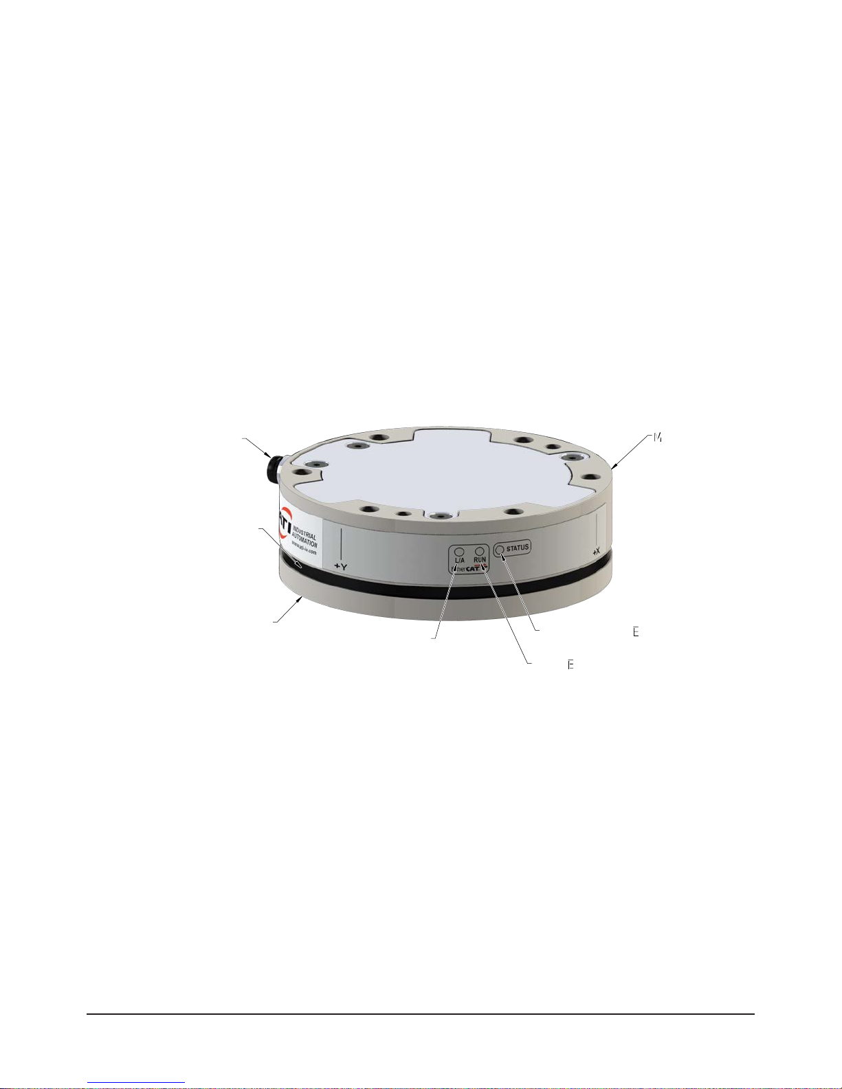
Figure 2.1—Axia80 EtherCAT F/T Sensor
6-Pin Male M8 Connector
for Power and
Communication
Dust Proof
Tool side
Tool side
(For Customer
Tooling)
Seal
Link/Activity LED
Sensor Status LED
Sensor Status LED
Run LED
Run LED
Mounting Side
Mounting Side
to Robot
to Robot
Pinnacle Park • 1031 Goodworth Drive • Apex, NC 27539 USA • Tel: +1.919.772.0115 • Fax: +1.919.772.8259 • www.ati-ia.com • Email: info@ati-ia.com
9
Page 10
Manual, F/T Sensor, Axia80 EtherCAT
Document #9610-05-Axia80 EtherCAT-09
2.1 LED Self-Test Sequence and Functions
The EtherCAT F/T provides (3) LEDs for EtherCAT Link, Run, and Sensor Status. When the user applies
power, the sensor completes a self-test, during which the LEDs under rmware control individually turn on.
2.1.1 LED Self-Test Sequence
When the user applies power to the sensor, the sensor completes a self-test, during which the LEDs
under rmware control individually turn on in the following sequence:
Sequence
Order
LED State Duration
1 Sensor Status Red
2 Run Red
3 EtherCAT Link/Activity Red
4 Sensor Status Green
5 EtherCAT Link/Activity Green
Note:
1. The Green Run LED is not tested in the self-test sequence.
2.1.2 EtherCAT Link/Activity LED
One LED signals link/activity on the EtherCAT port as follows:
Approximately one
second for each LED.
LED State Link Activity Condition
Off No No No EtherCAT connection.
Green Yes
Note:
1. This LED behavior is different from the standard EtherCAT device Link/Activity LED
behavior, which is a ashing green LED.
2.1.3 Run LED
One LED signals the communication status of the EtherCAT sensor interface as follows:
LED State Description
Off EtherCAT interface is in the state “INIT”.
Flashing green EtherCAT interface is in the state “Preoperational”.
Green EtherCAT interface is in the state “Operational”.
2.1.4 Sensor Status LED
One LED signals the health status of the sensor as follows:
LED State Description
Off No power.
Green
Flashing green
Amber Sensing range exceeded.
Red System error.
Normal operation.
The sensor’s electronics are functioning and communicating.
Power-up self testing.
At power-up, the sensor completes diagnostic testing to verify
internal electronics are functioning.
No
Yes
EtherCAT link/activity is detected.
1
Pinnacle Park • 1031 Goodworth Drive • Apex, NC 27539 USA • Tel: +1.919.772.0115 • Fax: +1.919.772.8259 • www.ati-ia.com • Email: info@ati-ia.com
10
Page 11

3. Installation
WARNING: Performing maintenance or repair on the sensor when circuits (e.g. power,
water, and air) are energized could result in death or serious injury. Discharge and verify all
energized circuits are de-energized in accordance with the customer’s safety practices and
policies.
CAUTION: Modication or disassembly of the sensor could cause damage and void the
warranty. Use the supplied mounting bolt pattern and the provided tool side mounting
bolt pattern to mount the sensor to the robot and customer tooling to the sensor. Refer to
Section 9—Drawings for more information.
CAUTION: Using fasteners that exceed the customer interface depth penetrates the body of
the sensor, damages the electronics, and voids the warranty. Refer to Section 9—Drawings
for more information.
CAUTION: Thread locker applied to fasteners must not be used more than once. Fasteners
may become loose and cause equipment damage. Always apply new thread locker when
reusing fasteners.
CAUTION: Avoid damage to the sensor from Electro-Static Discharge. Ensure proper
grounding procedures are followed when handling the sensor or cables connected to the
sensor. Failure to follow proper grounding procedures could damage the sensor.
Manual, F/T Sensor, Axia80 EtherCAT
Document #9610-05-Axia80 EtherCAT-09
CAUTION: Do not apply excessive force to the sensor and cable connector during
installation, or damage will occur to the connectors. Align the keyway on the sensor and cable
connector during installation to avoid applying excessive force to the connectors.
Keyway on the
sensor connector.
Keyway on the
cable connector.
NOTICE: Depending on the maintenance or repair being performed, utilities to the sensor may not
need to be disconnected.
3.1 Adapter Plates
The sensor’s mounting side attaches to the robot arm, and the sensor’s tool side attaches to the customer
tooling. If adapter plate(s) are required to interface the sensor to the robot arm and customer tooling, ATI
can supply custom robot and tool adapter plates. Refer to Section 9—Drawings of this manual for technical
information on the sensor’s mounting features.
CAUTION: Incorrect installation of robot mounting and tool adapter plates will result in
the failure of the F/T sensor to function properly. Because the mounting and tool sides
of the sensor have identical bolt patterns, verify the robot mounting and tool adapter
plates are installed correctly.
CAUTION: The customer tool should only touch the tool adapter plate. If the customer
tool touches any other part of the sensor, it will not properly sense loads.
Pinnacle Park • 1031 Goodworth Drive • Apex, NC 27539 USA • Tel: +1.919.772.0115 • Fax: +1.919.772.8259 • www.ati-ia.com • Email: info@ati-ia.com
11
Page 12

Manual, F/T Sensor, Axia80 EtherCAT
Document #9610-05-Axia80 EtherCAT-09
If the customer chooses to design and build an adapter plate(s), the following points should be considered:
• The adapter plate(s) should include bolt holes for mounting fasteners as well as dowel pin(s) and a
boss for accurate positioning to the robot or customer’s device.
• The thickness of the adapter plate(s) must provide sufcient thread engagement for the mounting
fasteners.
• The mounting fasteners should not extend through the sensor’s housing or interfere with the internal
electronics. Refer to Section 9—Drawings for thread depth, mounting patterns, and other details.
• Do not use dowel pin(s) that exceed length requirements and prevent the adapter plate(s) from
mating ush with the robot and customer tooling. Fasteners that exceed length requirements create
a gap between the interfacing surfaces and cause damage.
• The adapter plate(s) must not distort from the maximum force and torque values that can be applied
to the sensor. For these values, refer to Section8—Specications.
• The adapter plate(s) must provide a at and parallel mounting surface for the sensor.
Figure 3.1 —Adapter Plate(s)
Locating Dowel
Robot Arm
Mounting Fasteners
.002 in (.05 mm)
.002 in (.05 mm)
A
(6) M5 Mounting Fasteners
(6) M5 Mounting Fasteners
(Customer Supplied)
3 mm Locating Dowel Pin
(Customer Supplied)
.002 in (.05 mm)
.002 in (.05 mm)
B
Locating Boss
Locating Boss
Mounting Adapter Plate
Locating Dowel
F/T Sensor
4 mm Locating Dowel Pin
(Customer Supplied)
Tool Adapter Plate
(Customer Supplied)
Mounting Fasteners
(Customer Supplied)
Locating Dowel Pin
(Customer Supplied)
Pinnacle Park • 1031 Goodworth Drive • Apex, NC 27539 USA • Tel: +1.919.772.0115 • Fax: +1.919.772.8259 • www.ati-ia.com • Email: info@ati-ia.com
12
Page 13

Manual, F/T Sensor, Axia80 EtherCAT
Document #9610-05-Axia80 EtherCAT-09
3.2 Routing the Cable
The routing and bending radius of the cable depends upon the customer application. Unlike motionless
applications, where the cable is in a static condition, dynamic applications subject the cable to a repetitive
motion. For dynamic applications, restrain the cable at a distance that does not expose and damage the
sensor’s cable connection from the robot’s repetitive motion.
NOTICE: The maximum supported cable length is 25 m.
Figure 3.2—Routing of the Sensor Cable
Robot Arm
Mounting
Adapter Plate
Allow enough slack in
Sensor Cable
the cable to allow full range
of motion for the robot device.
Restrain cable to keep
repetitive motion from
F/T Sensor
affecting the cable
connection.
CAUTION: Do not subject the sensor’s cable connector to the repetitive motion
of the robot or other device. Subjecting the connector to the repetitive motion will
cause damage to the connector. Restrain the cable close to the connector so that the
repetitive motion of the robot does not interfere with the cable connector.
CAUTION: The cable must withstand the repetitive motions of the robot without failing.
The electrical line, especially where attached to the sensor’s connector, must be routed
to avoid stress failure, sharp bends, or a disconnection from the equipment. Improper
routing may cause poor functionality of critical electrical lines, injury to personnel, or
damage to equipment. Damage to the sensor or cable from improper routing will void
the warranty. If the application results in cable rubbing, use a loose, plastic spiral wrap
for protection.
CAUTION: When routing cables do not bend less than the minimum bending radius
specied in Table 3.1. A bend radius too small causes the cable to fail from fatigue of
the robot’s repetitive motion.
Pinnacle Park • 1031 Goodworth Drive • Apex, NC 27539 USA • Tel: +1.919.772.0115 • Fax: +1.919.772.8259 • www.ati-ia.com • Email: info@ati-ia.com
13
Page 14

Manual, F/T Sensor, Axia80 EtherCAT
Document #9610-05-Axia80 EtherCAT-09
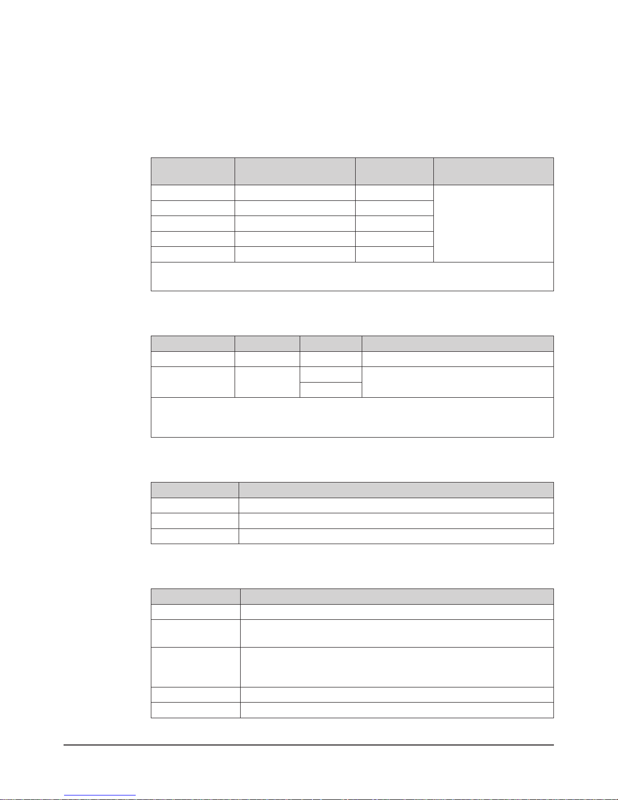
Table 3.1—Sensor Cable Bending Radius and Dynamic Twist Angle
Cable Part Number
9105-C-ZC22-ZC26-X N/A 7 (.28) 35 1.4 70 2.8
9105-C-ZC26-U-
RJ45S-X
Notes:
1. Temperature affects cable exibility. ATI recommends increasing the minimum dynamic bending radius for
lower temperatures.
Spliced Cable
Branch
Description
Branch 1,
Power
Branch 2,
EtherCAT
The 6-pin connector on the 9105-C-ZC22-ZC26-X power and EtherCAT cable attaches to the sensor’s
connector. The 9105-C-ZC26-U-RJ45S-X 8-pin connector attaches to the 9105-C-CZ22-ZC26-X power and
EtherCAT cable, of which branch 1 is an unterminated end for connection to power and branch 2 has a RJ45
connection for EtherCAT.
Route the sensor cable so that it is not stressed, pulled, kinked, cut, or otherwise damaged throughout the
full range of motion. If the application causes cable abrasion, use a loose plastic, spiral wrap to protect the
outer cable jacket material.
Static
Bending
Radius
Cable
Diameter
mm (in)
5.1 (.20) 25.5 1 51 2
5.7 (.22) 28.5 1.1 57 2.2
(at room
temperature)
mm in mm in
Dynamic
Bending
Radius
(at room
temperature)
Dynamic
Cable Twist
Angle per
Unit Length
180°/m or
55°/ft
CAUTION: Do not damage or crush the cable by over tightening tie wraps on the cable.
3.3 Installing the Sensor to the Robot
Parts required: Refer to Figure 3.3 and Section 9—Drawings.
Tools required: 4 mm hex wrench
Supplies required: Clean rag, Loctite® 242 (if applicable, refer to step 3 and 4)
1. Ensure the mounting surface of the mounting adapter plate and robot are clean and free of debris.
2. Attach the mounting adapter plate to the robot arm with the mounting fasteners.
3. Attach the sensor to the mounting adapter plate.
• Screws to have a minimum thread engagement length of 4.5 mm with a maximum thread
engagement less than the threaded depth listed in the customer drawing Section 9—Drawings.
• If the sensor is to be used in a high-vibration environment, Loctite 242 should be applied to the (6)
M5 socket head cap screws, class 12.9 so that the fasteners secure the sensor to the mounting plate.
a. Using a 4 mm Allen wrench, secure the sensor to the mounting adapter plate with the (6) M5 socket
head cap screws, class 12.9. Tighten to 52 in-lbs (5.88 Nm).
4. Once the sensor is installed on the robot, the customer tooling or tool interface plate can be installed.
• Screws to have a minimum thread engagement length of 4.5 mm with a maximum thread
engagement less than the threaded depth listed in the customer drawing Section 9—Drawings.
• If the sensor is to be used in a high-vibration environment, Loctite 242 should be applied to the
fasteners so that the fasteners secure the customer tooling to the sensor.
Pinnacle Park • 1031 Goodworth Drive • Apex, NC 27539 USA • Tel: +1.919.772.0115 • Fax: +1.919.772.8259 • www.ati-ia.com • Email: info@ati-ia.com
14
Page 15

Manual, F/T Sensor, Axia80 EtherCAT
Document #9610-05-Axia80 EtherCAT-09
NOTICE: The tool must not touch any other part of the sensor except the tool side; otherwise,
the sensor will not properly detect loads.
5. Connect the cable(s) to the sensor and customer application.
a. Connect a power and EtherCAT cable (ATI P/N 9105-C-ZC22-ZC26-X) to the sensor’s connection.
Tighten to 4.43 in-lbs (0.5 Nm).
b. Connect the branched cable (ATI P/N 9105-C-ZC26-U-RJ45S-X) to the cable from step a. Tighten
to 7.08 in-lbs (0.8 Nm).
c. Connect the RJ45 and power connections to the customer application. Refer to Section 2.1.1—LED
Self-Test Sequence for the LED outputs that occur whenever power is supplied to the sensor.
6. Properly restrain and route the power and EtherCAT cable; refer to Section 3.2—Routing the Cable.
7. After installation is complete, the sensor is ready for an accuracy check as described in Section 3.6—
Accuracy Check Procedure and then normal use.
Figure 3.3—Installation of Axia80 to the Robot
Robot
Dowel Pin
Mounting Fasteners
Interface Plate
Mounting
Fasteners
(2) Dowel Pin
Power and
EtherCAT
Connection
for Customer Tooling
Tool Side
Power and EtherCAT Cable to the sensor
(ATI P/N 9105-C-ZC22-ZC26-X)
(9105-IP-2118 shown)
Mounting to the Robot
or Interface Plate
Axia80 EtherCAT
Sensor
3.4 Removing the Sensor from the Robot
Tools required: 4 mm hex wrench
Note: Cable lengths are shortened
in the figure for reference only.
Power and EtherCAT cable to the customer application
(ATI P/N 9105-C-ZC26-U-RJ45S-X)
Unterminated End for Power
RJ45 Connector for EtherCAT
(Branch 1)
(Branch 2)
1. Turn off all energized circuits (e.g. electrical).
2. Remove the power and EtherCAT cable from the sensor’s connection.
3. Supporting the customer tooling and/or interface plate, remove the customer supplied screws that attach
to the customer tooling to the sensor.
4. Supporting the sensor, use a hex wrench to loosen the (6) M5 socket head cap screws that secure to the
sensor to the mounting interface plate or robot.
5. Remove the sensor.
Pinnacle Park • 1031 Goodworth Drive • Apex, NC 27539 USA • Tel: +1.919.772.0115 • Fax: +1.919.772.8259 • www.ati-ia.com • Email: info@ati-ia.com
15
Page 16

Manual, F/T Sensor, Axia80 EtherCAT
Document #9610-05-Axia80 EtherCAT-09
3.5 Pin Assignment for the EtherCAT and Power Connection
CAUTION: Ensure the cable shield is properly grounded. Improper shielding on the
cables can cause communication errors and inoperative sensors.
The following section provides the pin assignment for the power and EtherCAT connection on the sensor,
the 8-pin male M12 connector on the power and EtherCAT cable (P/N 9105-C-ZC22-ZC26-X), and the
unterminated end on cable (P/N 9105-C-ZC26-U-RJ45S-X) for power. Refer to
Specications, for supply voltage ratings.
3.5.1 Pin Assignment for the 6-pin M8 Male Connector on the Sensor
The following table details the signals and corresponding pin numbers on the M8 connector for
power and EtherCAT.
Table 3.2—Pin Assignment for the 6-pin, M8, Male Sensor Connector
(Power and EtherCAT)
Connector Schematic Pin Number Signal
3
4
6
5
2
1
1 TX+
2 TX3 RX+
4 RX5 V +
6 V -
Section 8.2—Electrical
3.5.2 Pin Assignment for the 8-Pin M12 Male Connector
on Cable P/N 9105-C-ZC22-ZC26-X
The following table details the signals and corresponding pin numbers for the 8-pin M12 connector
on cable P/N 9105-C-ZC22-ZC26-X that connects to cable P/N 9105-C-ZC26-U-RJ45S-X.
Table 3.3—Cable P/N 9105-C-ZC22-ZC26-X Pin Assignment
for the 8-pin, M12, Male Connector (Power and EtherCAT)
Connector Schematic Pin Number Signal
1 Shield
2 V +
3 V 4 TX5 RX+
6 TX+
7 No Connection
8 RX-
Pinnacle Park • 1031 Goodworth Drive • Apex, NC 27539 USA • Tel: +1.919.772.0115 • Fax: +1.919.772.8259 • www.ati-ia.com • Email: info@ati-ia.com
16
Page 17

Manual, F/T Sensor, Axia80 EtherCAT
Document #9610-05-Axia80 EtherCAT-09
3.5.3 Pin Assignment for Cable P/N 9105-C-ZC26-U-RJ45S-X, Branch 1,
Unterminated End for Power Connection
The following table details the signals and corresponding pin numbers for unterminated wires on
cable P/N 9105-C-ZC26-U-RJ45S-X that connects to the customer’s device.
Table 3.4—Cable 9105-C-ZC26-U-RJ45S-X, Branch 1, Unterminated
Pin Assignment
Pin Number Wire Jacket Color Signal
1 - Shield
2 Black V +
3 White V -
3.5.4 Pin Assignment for Cable P/N 9105-C-ZC26-U-RJ45S-X, Branch 2,
RJ45 Connection
The following table details the signals and corresponding pin numbers for the 8-pin RJ45 connector
on cable P/N 9105-C-ZC26-U-RJ45S-X that connects to the customer device.
Table 3.5—Cable P/N 9105-C-ZC22-ZC26-X Pin Assignment
for the 8-pin, RJ45 Connector
Connector Schematic Pin Number Wire Color Signal
1 White/Orange TX+
2 Orange TX3 White/Green RX+
4 - No Connection
5 - No Connection
6 Green RX7 - No Connection
8 - No Connection
Pinnacle Park • 1031 Goodworth Drive • Apex, NC 27539 USA • Tel: +1.919.772.0115 • Fax: +1.919.772.8259 • www.ati-ia.com • Email: info@ati-ia.com
17
Page 18

Manual, F/T Sensor, Axia80 EtherCAT
Document #9610-05-Axia80 EtherCAT-09
3.6 Accuracy Check Procedure
Complete the following procedures after the initial installation of the sensor to the robot and once annually
for maintenance.
1. Attach a xed mass to the tool side of the F/T sensor.
• The mass on the tool side can be the weight of the tooling used in an application.
a. Remove cables that form bridges between the sensor’s mounting and tool sides.
2. Move the robot so that the sensor is in the following positions.
a. Record the sensor’s output, F
• Point 1: +Z up
• Point 2: +X up
• Point 3: +Y up
• Point 4: -X up
• Point 5: -Y up
• Point 6: -Z up
, at each point without biasing.
x Fy Fz
3. Find F
x, average
, F
y, average
, and F
z, average
.
a. Perform the following equations.
4. For each of the 6 points, complete the following calculation:
5. Once the tooling mass has been calculated for all (6) points, the range of the tooling masses should be
less than twice the worst accuracy rating of the sensor.
• le max (tooling masses) - min(tooling masses) < 36 N
• In addition, the tooling mass should be within 36 N of the results of this test when it was
performed with a new sensor.
• If this test fails, then the sensor should be returned to ATI for diagnosis or recalibration.
Pinnacle Park • 1031 Goodworth Drive • Apex, NC 27539 USA • Tel: +1.919.772.0115 • Fax: +1.919.772.8259 • www.ati-ia.com • Email: info@ati-ia.com
18
Page 19

Manual, F/T Sensor, Axia80 EtherCAT
Document #9610-05-Axia80 EtherCAT-09
4. Operation
The following section provides information required when using software to operate the EtherCAT Sensor.
Communicating with the EtherCAT sensor requires knowledge of EtherCAT standards and operation.
4.1 Sensor Environment
CAUTION: Damage to the outer jacketing of the transducer cable could enable
moisture or water to enter an otherwise sealed transducer. Ensure the cable jacketing
is in good condition to prevent transducer damage.
NOTICE: Transducers may react to exceptionally strong and changing electromagnetic elds,
such as those produced by magnetic resonance imaging (MRI) machines.
To ensure proper operation, the IP60 rating of the sensor must match or exceed the transducer’s
environment.
4.2 Sample Rate
The “Sample Rate” eld in Section 5.2.8—Object 0x7010: Control Codes controls the current sample rate.
The following table lists the rounded and exact sample rates.
Table 4.1—Sample Rate
Rounded Sample Rate 0.5 kHz 1 kHz 2 kHz 4 kHz
Exact Sample Rate 487 Hz 975 Hz 1990 Hz 3900 Hz
4.3 Low-pass Filter
The power-on default selection is no ltering. The “Filter Selection” eld in Section 5.2.8—Object 0x7010:
Control Codes controls the current lter selection. The cutoff frequency (i.e. -3 dB frequency) is dependent
on the sample rate selection, which is dened in Section 4.2—Sample Rate. The cutoff frequencies for the
different sampling rates are listed in the following table and graphs:
Table 4.2—Low-Pass Filtering
Selected
Filter
0 200 350 500 1000
1 58 115 235 460
2 22 45 90 180
3 10 21 43 84
4 5 10 20 40
5 2.5 5 10 20
6 1.3 3 5 10
7 0.6 1.2 2.4 4.7
8 0.3 0.7 1.4 2.7
at 0.5 kHz
Sample Rate
-3dB Cutoff Frequency (in Hz)
at 1 kHz
Sample Rate
at 2 kHz
Sample Rate
Sample Rate
at 4 kHz
Pinnacle Park • 1031 Goodworth Drive • Apex, NC 27539 USA • Tel: +1.919.772.0115 • Fax: +1.919.772.8259 • www.ati-ia.com • Email: info@ati-ia.com
19
Page 20

Manual, F/T Sensor, Axia80 EtherCAT
0.3 Hz
0.6 Hz
1.3 Hz
2.5 Hz
5 Hz
10 Hz
22 Hz
60 Hz
Document #9610-05-Axia80 EtherCAT-09
Figure 4.1—Filter Attenuation at 0.5 kHz Sample Rate
0.0 dB
-6.0 dB
-12.0 dB
Attenuation
-18.0 dB
-24.0 dB
-30.0 dB
0.0 dB
-6.0 dB
-12.0 dB
Attenuation
-18.0 dB
-24.0 dB
0 Hz 1 Hz 10 Hz 100 Hz 1000 Hz
Frequency
Figure 4.2—Filter Attenuation at 1 kHz Sample Rate
350Hz
115 Hz
45 Hz
21 Hz
10 Hz
5 Hz
3 Hz
1.2 Hz
0.7 Hz
-30.0 dB
0 Hz 1 Hz 10 Hz 100 Hz 1000 Hz
Pinnacle Park • 1031 Goodworth Drive • Apex, NC 27539 USA • Tel: +1.919.772.0115 • Fax: +1.919.772.8259 • www.ati-ia.com • Email: info@ati-ia.com
Frequency
20
Page 21

0.0 dB
2.7 Hz
4.7 Hz
10 Hz
40 Hz
84 Hz
180 Hz
460 Hz
-6.0 dB
Manual, F/T Sensor, Axia80 EtherCAT
Document #9610-05-Axia80 EtherCAT-09
Figure 4.3—Filter Attenuation at 2 kHz Sample Rate
43 Hz
90 Hz
500 Hz
235 Hz
-12.0 dB
Attenuation
-18.0 dB
-24.0 dB
-30.0 dB
0.0 dB
-6.0 dB
20 Hz
10 Hz
5 Hz
2.4 Hz
1.4 Hz
0 Hz 1 Hz 10 Hz 100 Hz 1000 Hz
Frequency
Figure 4.4—Filter Attenuation at 4 kHz Sample Rate
1000 Hz
-12.0 dB
Attenuation
-18.0 dB
-24.0 dB
-30.0 dB
0 Hz 1 Hz 10 Hz 100 Hz 1000 Hz
Pinnacle Park • 1031 Goodworth Drive • Apex, NC 27539 USA • Tel: +1.919.772.0115 • Fax: +1.919.772.8259 • www.ati-ia.com • Email: info@ati-ia.com
Frequency
21
Page 22

Manual, F/T Sensor, Axia80 EtherCAT
Document #9610-05-Axia80 EtherCAT-09
5. EtherCAT Bus Interface
The EtherCAT bus interface enables users to perform the following actions:
• Read the active calibration information matrix, serial number, etc.
• Read the rmware revision
• Read force/torque data
• Read strain gage data and status information
• Set low-pass lter cutoff frequency
• Bias the transducer
• Change the sample rate
5.1 PDO Interface
The PDO interface exchanges data in real time with the F/T sensor.
a. TxPDO Map / Output Data
The TxPDO combines Object 0x6000: Reading Data, Object 0x6010: Status Code, and Object
0x6020: Sample Counter.
b. RxPDO Map / Input Data
The RxPDO map consists of Object 0x7010: Control Codes.
5.2 EtherCAT Dictionary Objects (SDO Data)
The SDO data congures the sensor and reads the manufacturing and calibration data. This section lists
dictionary objects specic to the EtherCAT F/T sensor application; it does not list objects that are a required
part of the EtherCAT standard. These dictionary objects can also be found in the ESI le: 9031-05-1049 on
the A TI website.
5.2.1 Object 0x2021: Calibration
This read-only object contains information about the currently active calibration selected by the
“Calibration Selection” eld in Section 5.2.8—Object 0x7010: Control Codes. It contains the
following elds:
Table 5.1—Calibration
Subindex Name Type Description
0x01 FT Serial STRING(8)
0x02
0x03 Calibration Family STRING(8) Always reads “ECAT”.
0x04 Calibration T ime STRING(30)
0x05 through
0x2e
0x2f Force Units USINT
Calibration Part
Number
Reserved DINT Reserved.
STRING(30)
The FT Serial Number,
e.g. “FT01234”.
The calibration part number
e.g. “SI-500-20”.
The date the sensor was
calibrated.
Value
0
1
2
3
4
Unit
Lbf
N
Klbf
kN
Kg
Pinnacle Park • 1031 Goodworth Drive • Apex, NC 27539 USA • Tel: +1.919.772.0115 • Fax: +1.919.772.8259 • www.ati-ia.com • Email: info@ati-ia.com
22
Page 23

Manual, F/T Sensor, Axia80 EtherCAT
Document #9610-05-Axia80 EtherCAT-09
Table 5.1—Calibration
Subindex Name Type Description
Value
0
1
0x30 Torque Units USINT
0x31 Max Fx Counts
0x32 Max Fy Counts
0x33 Max Fz Counts
0x34 Max Tx Counts
0x35 Max Ty Counts
0x36 Max Tz Counts
0x37 Counts Per Force DINT
0x38 Counts Per Torque DINT
0x39 through
0x56
Reserved UINT Reserved.
DINT
The maximum rated value for
this axis, in counts.
The calibration counts per
force unit.
The calibration counts per
torque unit.
2
3
4
5
0x57 PeakLoadsPosFx
0x58 PeakLoadsPosFy
0x59 PeakLoadsPosFz
0x5a PeakLoadsPosTx
DINT
Peak Loads Positive. All-time
peak positive force/torque
loads in counts per unit.
0x5b PeakLoadsPosTy
0x5c PeakLoadsPosTz
0x5d PeakLoadsNegFx
0x5e PeakLoadsNegFy
0x5f PeakLoadsNegFz
0x60 PeakLoadsNegTx
0x61 PeakLoadsNegTy
DINT
Peak Loads Negative. Alltime peak negative force/
torque loads in counts per
unit.
0x62 PeakLoadsNegTz
0x63 through
0x7c
Reserved.
Unit
lbf-in
lbf-ft
Nm
Nmm
Kgf-cm
kNm
Pinnacle Park • 1031 Goodworth Drive • Apex, NC 27539 USA • Tel: +1.919.772.0115 • Fax: +1.919.772.8259 • www.ati-ia.com • Email: info@ati-ia.com
23
Page 24

Manual, F/T Sensor, Axia80 EtherCAT
Document #9610-05-Axia80 EtherCAT-09
5.2.2 Object 0x2080: Diagnostic Readings
This read-only object provides rmware version information. The following elds are available in
the version object:
Subindex Name Type Description
0x01 Supply Voltage UINT16
0x02 Gage Temperature INT16
0x03 Status Message STRING(40)
Table 5.3—Errors in the Diagnostic Readings Status Message
Priority Text Error Messages
1 Supply voltage out of range.
2 Gage temperature out of range.
3 Calibration checksum error.
4 Gage(s) disconnected: <list>
5 Gage(s) out-of-range: <list>
6 Force/torque out of range.
7 Hardware or stack error.
8 Simulated error.
9 Error (unspecied).
10 No status code errors.
Table 5.2—Diagnostic Readings
The voltage of the external
power supply x 10.
The transducer temperature
in °C x 10.
A priority status code error
message. Refer to Table 5.3.
Pinnacle Park • 1031 Goodworth Drive • Apex, NC 27539 USA • Tel: +1.919.772.0115 • Fax: +1.919.772.8259 • www.ati-ia.com • Email: info@ati-ia.com
24
Page 25

5.2.3 Object 0x2090: Version
This read-only object provides rmware version information. The following elds are available in
the version object:
Table 5.4—Version
Subindex Name Type Description
0x01 Major UINT Major Version
0x02 Minor UINT Minor Version
0x03 Revision UINT Revision
0x04 Boatloader Version UDINT Bootloader Version
5.2.4 Object 0x6000: Reading Data
This read-only object represents the current force/torque and is mapped into the
TxPDO input data. The following elds are present in the reading data:
Table 5.5—Reading Data
Subindex Name Type Description
0x01 Fx
0x02 Fy
0x03 Fz
0x04 Tx
0x05 Ty
0x06 Tz
DINT
Manual, F/T Sensor, Axia80 EtherCAT
Document #9610-05-Axia80 EtherCAT-09
These elds contain the 32-bit F/T
result data, in counts per unit.
Pinnacle Park • 1031 Goodworth Drive • Apex, NC 27539 USA • Tel: +1.919.772.0115 • Fax: +1.919.772.8259 • www.ati-ia.com • Email: info@ati-ia.com
25
Page 26

Manual, F/T Sensor, Axia80 EtherCAT
Document #9610-05-Axia80 EtherCAT-09
5.2.5 Object 0x6010: Status Code
This object contains a single DINT value (at subindex 0), with the following bitmap:
Bit
Number
0
1
2
3
4 Reserved. No
5 Hardware or stack error. Yes
Description
Internal Temperature Out of Range: This bit is active (high) if the
temperature is outside the range -5 to 70°C.
Supply Voltage Out of Range: This bit is active (high) if the input
voltage is outside the range of 12 V to 30 V.
Busy: The bit is active (high) when the sensor is modifying
parameters that may temporarily affect sending F/T data.
Busy Bit. The sensor is performing (1) or more of the following
activities that may temporarily affect the F/T data:
• Committing a change to Object 0x2021.
• Changing the lter time constant.
• Changing the calibration in use.
• Changing the ADC sampling rate.
• Writing to ash memory.
• Any ADC ISR overrun.
Table 5.6—Status Code
Indicates
an Error?
Yes
Yes
Yes
Yes
6-15 Reserved. No
16-26 Reserved. No
27
Gage Out of Range: The bit is active if a strain gage output
operating range has been exceeded in any of the past 32 samples.
Yes
Simulated Error. This bit mirrors the “Simulated Error Control” bit in
28
Section 5.2.8—Object 0x7010: Control Codes. It can be used to test
Yes
user error handling.
29
30
Calibration checksum error: This bit is set if the active calibration
has an invalid checksum.
Sensing Range Exceeded
1
: This bit is set whenever a F/T reading
exceeds the calibrated range. This check occurs before digital
Yes
Yes
ltering.
31
Note:
1. Sensing Range Exceeded is comparable to what previous F/T sensor manuals identied as
Error: This bit is set whenever any status code bit that indicates an
error is set.
saturation.
Yes
Pinnacle Park • 1031 Goodworth Drive • Apex, NC 27539 USA • Tel: +1.919.772.0115 • Fax: +1.919.772.8259 • www.ati-ia.com • Email: info@ati-ia.com
26
Page 27

5.2.6 Object 0x6020: Sample Counter
This object contains a single 32-bit unsigned integer at subindex 0 that increases by one each time
an F/T sample (one complete set of gage data) is read.
This number rolls over from 4 294 967 295 (232-1) to 0 without signalling an error. The sample
counter is reset to zero during power up.
5.2.7 Object 0x6030: Gage Data
This read-only object reads the latest raw gage data.
Table 5.7—Control Codes
Subindex Name Type Description
0x01 Gage 0
0x02 Gage 1
0x03 Gage 2
0x04 Gage 3
0x05 Gage 4
0x06 Gage 5
0x07 Gage 6
DINT These elds contain the latest raw gage values.
Manual, F/T Sensor, Axia80 EtherCAT
Document #9610-05-Axia80 EtherCAT-09
Pinnacle Park • 1031 Goodworth Drive • Apex, NC 27539 USA • Tel: +1.919.772.0115 • Fax: +1.919.772.8259 • www.ati-ia.com • Email: info@ati-ia.com
27
Page 28

Manual, F/T Sensor, Axia80 EtherCAT
Document #9610-05-Axia80 EtherCAT-09
5.2.8 Object 0x7010: Control Codes
This object is mapped into the RxPDO for real-time control of the F/T system. It contains the
following elds:
Subindex Name Type Description
0x01 Control 1 DINT
0x02 Control 2 DINT
Note:
1. This bit must be returned to 0 for the sensor to read properly, after a bias command is
entered. If this bit is held at 1, then the sensor will continuously bias and output readings of
zero in all axes.
Table 5.8—Control Codes
Bit Function
0
1 = Set bias against current load
0 = Use last set bias
1 Reserved
2
1 = clear bias
0 = leave bias unchanged
3 Reserved
The low-pass lter selection.
4-7
0 = No ltering
1 - 8 = Refer to
for details.
Active calibration.
8-11
Calibration slot 0, refer to Table 8.3.
Calibration slot 1, refer to Table 8.3.
2 through 15 = Reserved.
Sample Rate
0 = 487 Hz
12-15
1 = 975 Hz
2 = 1990 Hz
3 = 3900 Hz
16-31 Reserved
Bit Function
0-30 Reserved
31 Simulated Error Control
1
Section 4.3—Low-pass Filter
Pinnacle Park • 1031 Goodworth Drive • Apex, NC 27539 USA • Tel: +1.919.772.0115 • Fax: +1.919.772.8259 • www.ati-ia.com • Email: info@ati-ia.com
28
Page 29

Manual, F/T Sensor, Axia80 EtherCAT
Document #9610-05-Axia80 EtherCAT-09
5.3 Establishing Communication with the Axia80 EtherCAT Sensor
The following steps guides the user through initializing communication between the Axia80 EtherCAT
sensor and the customer’s EtherCAT master device. Always refer to the software manual for the EtherCAT
master device for instructions best suited for your application.
1. Attach the sensor to the EtherCAT and power cables. Refer to Section 3.3—Installing the Sensor to the
Robot and Section 3.5—Pin Assignment for the EtherCAT and Power Connection.
2. Import the ESI le: 9031-05-1049 from the ATI website into the EtherCAT master software
• Specic steps to import the ESI le varies among the different EtherCAT master software and
hardware available to the customer.
3. Congure the EtherCAT master device to communicate with the Axia80 EtherCAT sensor.
4. In the software for the EtherCAT master, read the calibration data at system start by using a SDO read to
object 0x2021, the calibration object.
5. Upon receipt of each real-time PDO sample, divide the force and torque counts values by the counts per
force and counts per torque values from the calibration object to calculate the F/T units values.
• F/T units are in the units specied in the calibration.
• For different units, the software for the EtherCAT master device can adjust the counts per force and
counts per torque values so that the resulting units are in the desired units.
• For example: If the calibration outputs 1, 000, 000 counts per Newton (N), to calculate the
output in counts per pound force (lbf), perform the following conversion:
6. Maintenance
6.1 Periodic Inspection
With industrial-type applications that frequently move the system’s cabling, you should check the cable
jacket for signs of wear. The Axia80 is IP60 rated and must be kept free of moisture. Debris and dust should
be kept from accumulating on or in the sensor. The surface of the sensor can be cleaned with isopropyl
alcohol, if contaminated by its environment. The sensor itself should experience no wear, if used within the
operating ranges and fastened to the proper torque specications. Refer to Section8—Specications and
Section 3.3—Installing the Sensor to the Robot.
6.2 Periodic Calibrating
Periodic calibration of the sensor and its electronics is required to maintain traceability to national standards.
Follow applicable ISO-9000-type standards for calibration. ATI Industrial Automation recommends annual
accuracy checks. Refer to Section 3.6—Accuracy Check Procedure.
Pinnacle Park • 1031 Goodworth Drive • Apex, NC 27539 USA • Tel: +1.919.772.0115 • Fax: +1.919.772.8259 • www.ati-ia.com • Email: info@ati-ia.com
29
Page 30

Manual, F/T Sensor, Axia80 EtherCAT
Document #9610-05-Axia80 EtherCAT-09
7. Troubleshooting
The information in this section should answer many questions that might arise in the eld. Customer service is
available for problems or questions not addressed in the manuals.
7.1 Errors with Force and Torque Readings
Inaccurate data from the transducer’s strain gages can cause errors in force/torque readings. These errors can
result in problems with transducer biasing and accuracy. Listed in the following table are the basic problems
of inaccurate data.
Question/Problem Answer/Solution
Jumps in force torque data readings (with the sensor unloaded) greater
than 0.05% of full scale counts is abnormal. Noise can be caused by
mechanical vibrations and electrical disturbances, possibly from a poor
Noise
Drift
Hysteresis
Sensor not streaming
measurement data to the
customer devices that use
EtherCAT eldbus.
ground. Noise can also indicate component failure within the system.
Make sure that the DC supply voltage for the Axia80 sensor has little
to no noise superimposed. The sensor should be grounded through
installation construction.
After a load is removed or applied, the raw gage reading does not
stabilize but continues to increase or decrease. A shift in the raw gage
reading is observed more easily in the resolved data mode using the
bias command. Some drift from a change in temperature or mechanical
coupling is normal.Mechanical coupling occurs when a tool plate
contacts the sensor body, for example, debris between the tool adapter
plate and the sensor body or in applications such as hoses and wires
attached to a tool.
When the sensor is loaded and then unloaded, gage readings do not
return quickly and completely to their original readings. Hysteresis is
caused by mechanical coupling (explained in Drift section) or internal
failure.
Verify the sensor is correctly installed. Ensure the robot mounting and
tool adapter plates are installed on the proper side of the sensor. Refer
to
Section 3—Installation for more information.
Pinnacle Park • 1031 Goodworth Drive • Apex, NC 27539 USA • Tel: +1.919.772.0115 • Fax: +1.919.772.8259 • www.ati-ia.com • Email: info@ati-ia.com
30
Page 31

Manual, F/T Sensor, Axia80 EtherCAT
Document #9610-05-Axia80 EtherCAT-09
8. Specications
The requirements for the EtherCAT sensor interface are covered in the following sections.
8.1 Storage and Operating Conditions
Table 8.1—Environmental Conditions
Parameter Value
Storage Temperature, °C -20 to +85
Operating Temperature, °C 0 to +65
Relative Humidity <95%, non-condensing
8.2 ElectricalSpecications
Table 8.2—Power Supply
Power Source Voltage Maximum Power Consumption
DC Power 12 V min. to 30 V max. 1.5 W
Notes:
1. The power supply input is protected from a reversed polarity circuit.
8.3 Calibration Ranges
1
Table 8.3—Calibration Range 0 and Calibration Range 1
Parameter Calibration Range 0 Calibration Range 1
Fxy 500 N 200 N
Fz 900 N 360 N
Txyz 20 Nm 8 Nm
Notes:
1. Each sensor is calibrated with these values.
Pinnacle Park • 1031 Goodworth Drive • Apex, NC 27539 USA • Tel: +1.919.772.0115 • Fax: +1.919.772.8259 • www.ati-ia.com • Email: info@ati-ia.com
31
Page 32

Manual, F/T Sensor, Axia80 EtherCAT
A
Document #9610-05-Axia80 EtherCAT-09
9. Drawings
Date
11/4/16
Initiator
ANG
Description
Initial Release
Rev.
01
5.2
3 Slip Fit
Customer Interface
34.348±0.025
+X
68.697±0.025
5.2
4 Slip Fit
Customer Interface
Sensing Reference Frame Origin
25.4
8.5
Location
4 Slip Fit
Indicator LED
Customer Interface
2X
)
3.
(Note
)
3.
(Note
2X 9.204±0.025
)
3.
(Note
15°
15°
-Y
+Y
+Z
-Z
+Y
5.2
6X M5x0.8 Tap
71.12
B.C.
Tool Side
Mounting Side
50.2
)
3.
(Note
Equally Spaced
Customer Interface
30°
-X
Frame Origin
Sensing Reference
L
C
6.97
To Connector
5.
Note
82
TOOL SIDE
SIDE VIEW
-Z
NOTES: UNLESS OTHERWISE
Note Key Orientation
01
REVISION
ISO 9001 Registered Company
Fax: +1.919.772.8259 www.ati-ia.com
Tel: +1.919.772.0115 Email: info@ati-ia.com
1031 Goodworth Drive, Apex, NC 27539, USA
MANNER EXCEPT ON ORDER OR WITH PRIOR WRITTEN AUTHORIZATION OF ATI.
PROPERTY OF ATI INDUSTRIAL AUTOMATION, INC. NOT TO BE REPRODUCED IN ANY
TITLE
SPECIFIED.
DO NOT SCALE DRAWING.
ALL DIMENSIONS ARE IN
MILLIMETERS.
9230-05-1507
DRAWING NUMBER
B
SIZE
1:1
SCALE
Axia80 Force/Torque Sensor
1 1
SHEET OF
A. Glusiec 11/4/16
I. Stern 11/4/16
141028-1
PROJECT #
DRAWN BY:
CHECKED BY:
3rd ANGLE PROJECTION
+Z
Connector View
+X
68.697±0.025
34.348±0.025
Pinnacle Park • 1031 Goodworth Drive • Apex, NC 27539 USA • Tel: +1.919.772.0115 • Fax: +1.919.772.8259 • www.ati-ia.com • Email: info@ati-ia.com
-Y
2X 9.204±0.025
71.12
B.C.
-X
8.5
)
3.
(Note
Equally Spaced
Customer Interface
6X M5X0.8 Tap
32
30°
MOUNTING SIDE
ISOMETRIC VIEW
Material: Aluminum and Stainless Steel
Do not touch internal electronics or instrumentation. This could 2.damage transducer and will void the warranty.
Do not exceed interface depth, may cause incorrect readings.
For best accuracy, transducer must be mounted to a surface rigid 4.enough to support loads without deflection
Notes:
1.
Recessed cover plate surface is not structural. Mount transducer to a 5.flat surface that makes contact around the perimeter.
3.
Page 33

Manual, F/T Sensor, Axia80 EtherCAT
Document #9610-05-Axia80 EtherCAT-09
10. Terms and Conditions of Sale
The following Terms and Conditions are a supplement to and include a portion of ATI’s Standard Terms and
Conditions, which are on le at ATI and available upon request.
ATI warrants to Purchaser that force torque sensor products purchased hereunder will be free from defects in
material and workmanship under normal use for a period of one (1) year from the date of shipment. The warranty
period for repairs made under a RMA shall be for the duration of the original warranty, or ninety (90) days from
the date of repaired product shipment, whichever is longer. ATI will have no liability under this warranty unless:
(a) ATI is given written notice of the claimed defect and a description thereof with thirty (30) days after Purchaser
discovers the defect and in any event, not later than the last day of the warranty period and (b) the defective item
is received by ATI not later than (10) days after the last day of the warranty period. ATI’s entire liability and
Purchaser’s sole remedy under this warranty is limited to repair or replacement, at ATI’s election, of the defective
part or item or, at ATI’s election, refund of the price paid for the item. The foregoing warranty does not apply to any
defect or failure resulting from improper installation, operation, maintenance, or repair by anyone other than ATI.
ATI will in no event be liable for incidental, consequential, or special damages of any kind, even if ATI has been
advised of the possibility of such damages. ATI’s aggregate liability will in no event exceed the amount paid by the
purchaser for the item which is the subject of claim or dispute. ATI will have no liability of any kind for failure of
any equipment or other items not supplied by ATI.
No action against ATI, regardless of form, arising out of or in any way connected with products or services supplied
hereunder, may be brought more than one year after the cause of action accrued.
No representation or agreement varying or extending the warranty and limitation of remedy provisions contained
herein is authorized by ATI, and may not be relied upon as having been authorized by ATI, unless in writing and
signed by an executive ofcer of ATI.
Unless otherwise agreed in writing by ATI, all designs, drawings, data, inventions, software, and other technology
made or developed by ATI in the course of providing products and services hereunder, and all rights therein under
any patent, copyright, or other law protecting intellectual property, shall be and remain ATI’s property. The sale
of products or services hereunder does not convey any expressed or implied license under any patent, copyright,
or other intellectual property right owned or controlled by ATI, whether relating to the products sold or any other
matter, except for the license expressly granted below.
In the course of supplying products and services hereunder, ATI may provide or disclose to Purchaser condential
and proprietary information of ATI relating to the design, operation, or other aspects of ATI’s products. As between
ATI and Purchaser, ownership of such information, including without limitation any computer software provided
to Purchaser by ATI, shall remain in ATI and such information is licensed to Purchaser only for Purchaser’s use in
operating the products supplied by ATI hereunder in Purchaser’s internal business operations.
Without ATI’s prior written permission, Purchaser will not use such information for any other purpose of provide or
otherwise make such information available to any third party. Purchaser agrees to take all reasonable precautions to
prevent any unauthorized use or disclosure of such information.
Purchaser will not be liable hereunder with respect to disclosure or use of information which: (a) is in the public
domain when received from ATI, (b) is thereafter published or otherwise enters the public domain through no fault
of Purchaser, (c) is in Purchaser’s possession prior to receipt from ATI, (d) is lawfully obtained by Purchaser from a
third party entitled to disclose it, or (f) is required to be disclosed by judicial order or other governmental authority,
provided that, with respect to such to maintain the condentiality of such information.
Pinnacle Park • 1031 Goodworth Drive • Apex, NC 27539 USA • Tel: +1.919.772.0115 • Fax: +1.919.772.8259 • www.ati-ia.com • Email: info@ati-ia.com
33
 Loading...