

ATI Technologies AT4000 Owner's Manual
AT4000 SIGNATURE SERIES
PURE BALANCED™
2 TO 7-CHANNEL POWER AMPLIFIER
OWNER’S GUIDE
Please Read First
CAUTION: To reduce th e risk of electrical shock, do not
remove the cover (or back). No user serviceable parts inside. Refer servicing to qualified service personnel.
WARNING: To reduce th e risk of fire or electric shock,
do not expose this appliance to rain or moisture.
PRECAUTIONS:
The amplifier is a wideband design with substantial power output capability. Certain precautions must be taken to
ensure proper operation.
1. Never expose the unit to moisture
2. Never plug an input cable into the amplifier while
the amplifier is turned on.
3. Never apply the “thumb test” (touching the “hot” lead of
the input cable with your finger) to the tip of the input cable
or input jack of the amplifier. RF rectification and/or hum
will be created and could cause damage to the loudspeakers.
ATI will not be responsible for damage to the loudspeakers
due to improper use of the equipment.
4. Under no circumstances should the output terminals of the
amplifier be short-circuited.
5. Avoid restricting the airflow around the unit. Good
airflow is necessary to help insure proper operation.
6. Be sure that the loudspeakers connected can handle the
output power of the amplifier at the loudspeakers rated
impedance. The warranty on the amplifier does not cover
damage to loudspeakers that have inadequate power handling capabilities.
7. Do not stack other system components or any other materials directly on top of the unit. The heat dissipating system
of the amplifier depends on free flowing air around the chassis.
The lightning flash with arrowhead, within an equilateral triangle, is intended to
alert the user to the presence of uninsulated “dangerous voltage” within the
product’s enclosure that may be of sufficient magnitude to constitute a risk of
electrical shock to persons.
The exclamation point within an equilateral triangle is intended to alert the user to
the presence of important operation
maintenance (servicing) instructions in
the literature accompanying the appli-
ance.
Safety Instructions
WARNING: TO REDUCE THE RISK OF FIRE OR
ELECTRIC SHOCK, DO NOT EXPOSE THIS UNIT TO
RAIN OR MOISTURE.
Read all the safety and operating instructions before
connecting or using this unit.
All warnings on the unit and in this operating manual should be
adhered to.
All operating and use instructions should be followed.
Do not use this unit near water: for example, near a bathtub,
washbowl, kitchen sink, laundry tub, in a wet basement, or near
a swimming pool.
This unit should be installed so that its location or position
does not interfere with its proper ventilation. For example,
It should not be situated on a bed, sofa, rug, or similar surface
that may block the ventilation openings: or placed in a built-in
installation, such as bookcase or cabinet, that may impede the
flow of air through its ventilation openings.
The unit should be situated away from heat sources such as
radiators, heat registers, stoves, or other devices (including
amplifiers) that produce heat.
The unit should be connected to a power-supply outlet only of the
voltage and frequency marked on its rear panel.
The power-supply cord should be routed so that it is not likely to
be walked on or pinched, especially near the plug, convenience
receptacles, or where the cord exits from the unit.
Clean unit only as recommended in this instruction manual.
The power-supply cord of the unit should be unplugged from the
wall outlet when it is to be unused for a long period of time.
Care should be taken so that objects do not fall, and liquids are
not spilled, into the enclosure through any openings.
The unit should be serviced by qualified service personnel when:
1. The power cord or the plug has been damaged; or
2. Objects have fallen, or liquid has been spilled, into the
unit; or
3. The unit has been exposed to rain, or liquids of any kind; or
4. The unit does not appear to operate normally, or exhibits a
marked change in performance; or
5. The device has been dropped, or the enclosure damaged.
To prevent electric shock, do not use the polarized plug with an
extension cord, receptacle or other outlet unless the blades can
be fully inserted to prevent blade exposure.
Page 2
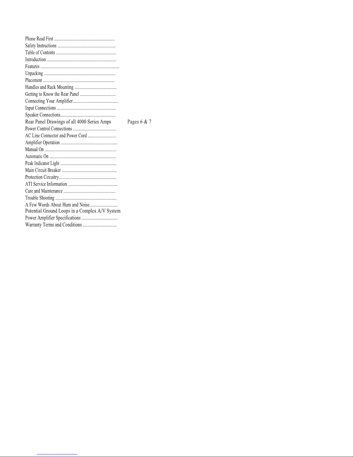
Table of Contents
Page 2
Page 2
Page 3
Page 3
Page 3
Page 3
Page 3
Page 3
Page 4
Page 4
Page 5
Page 5
Page 8
Page 8
Page 8
Page 8
Page 8
Page 8
Page 9
Page 9
Page 9
Page 9
Page 9
Page 10
Page10
Page 11
Page 12
AT4000 Signature Series
Pure Balance™ Power Amplifiers
Congratulations! Thank you for purchasing our Signature
Series Amplifier. Designed, engineered and manufactured in the United States, it offers significant advances
in circuit topology and performance over virtually all
currently available amplifiers.
The AT4000 Signature Series is comprised of six models;
AT4002 two-channel amplifiers, AT4003 three-channel
amplifiers, AT4004 four-channel amplifiers, AT4005 fivechannel amplifiers, AT4006 six-channel amplifiers and the
AT4007 seven-channel amplifiers. This manual covers all
six models with the only difference being the number of
channels.
In order to receive the maximum performance from your
new amplifier, please take a few minutes to read this manual. This important information will help you make certain
that the amplifier is properly configured for operation with
the rest of the equipment in your system. If you have any
questions about this product, its installation or operation,
please contact us via e-mail at support@ati-amp.com or via
telephone at (323) 278-0001.
Features
Your new ATI amplifier is a state of the art, high performance,
audio component. It is built utilizing fully balanced circuitry.
Dual custom-designed, toroidal transformers drive the high current power supply with independent secondary windings for each
channel. Each output module employs an advanced optically
coupled protection circuit that replaces the need for bothersome
fuse changes. The amplifier is cooled by convection through the
use of custom designed, efficient heat sinks.
Unpacking
The carton and packing materials used in shipping your new am-
plifier were specially designed to protect it from the shock and
vibration of shipping. We strongly suggest that you save the car-
ton and packing materials to use if you move, or if the unit ever
needs to be shipped back to us for any reason. Should you discov-
er that your amplifier has been damaged during shipping, please
contact your dealer or ATI immediately and request the name of
the carrier so a written claim may be made.
THE RIGHT TO A CLAIM AGAINST A PUBLIC CARRIER
CAN BE FORFEITED IF THE CARRIER IS NOT NOTIFIED
PROMPTLY IN WRITING AND IF THE SHIPPING CARTON
AND PACKING MATERIALS ARE NOT AVAILABLE FOR
INSPECTION BY THE CARRIER. SAVE ALL PACKING
MATERIALS UNTIL THE CLAIM IS SETTLED.
Placement
During normal home operation the chassis and top-cover of the
amplifier will become warm. However, there are instances during
high level playback into low impedance speakers when the chassis and top-cover may become much warmer than usual. To ensure the amplifier’s trouble-free operation, it is necessary to provide adequate ventilation for the heat sinks. Your amplifier
should be kept away from external sources of heat such as radiators and hot-air ducts. The amplifier should never be placed with
other heat-producing components in a cabinet or enclosure lacking free airflow. Do not stack other components on top of your
amplifier.
Handles and Rack Mounting
The handles on the AT4000 Series may be removed by using an
Allen wrench. Carefully remove the four socket-head cap screws
and replace them with screws of the same diameter and pitch, but
only 1 inch long. Do not use longer bolts as they may penetrate
too deeply and damage internal parts. Your amplifier may be
mounted in a standard 19-inch rack by using the optional 19-inch
rack mount panel.
CAUTION: THE RACK MOUNT PANEL CANNOT SUPPORT THE WEIGHT OF YOUR AMPLIFIER. BE SURE TO
MOUNT THE UNIT ON A STRONG, WELL-SUPPORTED
SHELF.
Page 3
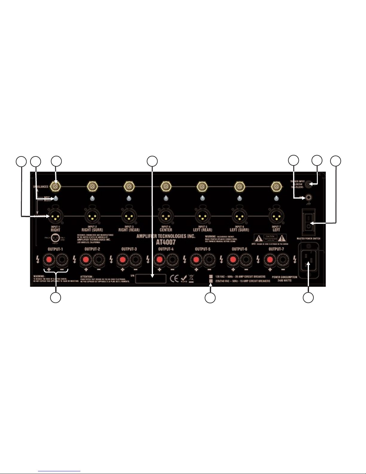
Getting to Know the Rear Panel
A. Balanced XLR Audio Inputs
Use the BALANCED INPUT jacks to connect to the outputs
of a preamplifier or other control device with XLR outputs.
B. Input Selector Switch
Selects either the BALANCED INPUT (XLR) or the UNBALANCED (RCA) INPUT jack.
C. Unbalanced Audio Inputs
Use the UNBALANCED INPUT jacks to connect to the outputs of a preamplifier, receiver with preout connections, CD
player, or other source device with RCA style outputs.
D. Product Serial Number
Enter into the space provided on Page 10.
E. Ground Terminal
Use to interconnect chassis where necessary.
A B C D E F G
F. Remote Trigger Input
Use the REMOTE TRIGGER jack to connect to a compatible
preamplifier, source device, or other product with a
3.3-24 VDC output.
G. Master Power Switch
Turns the current to the amplifier on or off.
H. Speaker Outputs
Use the OUTPUT binding posts to connect the amplifier to your
speakers; red for positive, black for negative.
I. Power Supply Voltage Indicator
The proper line-voltage is marked in green.
J. AC Input
Use the included power cord to connect your amplifier to an
AC power source.
H I J
Connecting Your Amplifier
When making connections between any source components and the amplifier, or when making connections to any speaker, be certain
that both the input devices and the amplifier are turned off. To assure that there will be no unwanted signal transients that can damage
equipment or speakers, it is always best to unplug all equipment before making any connections.
Page 4
 Loading...