

Page 1

ALL-IN-WONDER™ 128 /
ALL-IN-WONDER™ 128 PRO
Installation and Setup
User’s Guide
Version 3.0 P/N 137-70090-30 Rev. C
© Copyright 1999, by ATI Technologies Inc.
All rights reserved, including those to reproduce this guide or parts thereof, in any form without
the express written permission of ATI Technol ogies Inc.
Features and specifications are subject to change without notice. Trademarks and/or registered
trademarks are the properties of their respective owners:
ALL-IN-WONDER 128 ALL-IN-WOND ER 128 PRO , RAG E 128 – ATITechnologiesInc.;
dbx – dbx Professional Products; Macintosh – Apple Computer Inc.; Macrovision – Macrovision
Corporation; Direct3D, NetMeeting, Windows3.1x, Windows95, Windows98, Windows NT –
Microsoft Corp.; Celeron, Indeo, Pentium, Pentium Pro – IntelCorporation; VGA – International
Business Machines Corp.; VESA – Video Electronics Standards Association;
WaveTop – WavePhore WaveTop Inc.; WebTV – WebTV Networks.
iii
Page 2

Disclaimer
The manufacturer (MFR) reserves the right to make changes to this
document and the products which it describes without notice. The
MFR shall not be liable for technical or editorial errors or omissions
made herein; nor for incidental or consequential damages resulting
from the furnishing, performance, or use of this material.
The MFR makes no repre se ntatio n th at the in te rcon ne c tion of pro du cts
in the manner described herein will not infringe on existing or future
patent rights, nor do the descri ptions contained herein imply the
granting of license to make, use or sell equipment constructe d in
accordance with this description.
The PCI accelerators have been designed to support the PCI local bus
standards. Some computers use proprietary local bus circuitry and
therefore may not be fully compatible with the MFR’s local bus cards.
Although tested successfully in a wide variety of computer systems, the
MFR cannot be held responsible for any incompatibilities which may
occur between this card and the system configuration you plan to use.
We recommend that you check with the deal er or di st ributor for your
computer system before installing your card.
Product Notices
Macrovision Corporation
This device is protected by U.S. Patent numbers 4,631,603,4,577,216,
and 4,819,098 and other intellectual property rights.
The use of Macrovision’s Copy Protection technology in the device
must be authorized by Macrovision and is in te nd ed fo r h ome a nd othe r
limited pay-per-view uses only, unless otherwise authorized in writing
by Macrovision. Reverse engineering or disassembly is prohibited.
Dolby* Laboratories, Inc.
Manufactured under license from Dolby Laboratories. Confidential
Unpublished Works. (c) 1992-1997 Dolby Laboratories, Inc. All rights
reserved.
ii
Page 3

Table of Contents
Getting Started............................................... .... ............5
Using this Guide............................................................................................6
What is the ALL-IN-WONDER 128 Family?...............................................7
System Requirements....................................................................................8
Other Sources of Information........................................................................9
Readme File............................................................................................9
Online Help ............................................................................................9
Online manual ......................................................................................10
ATI Multimedia Center Guide.............................................................10
Installing the Hardware and Software .......................11
Installing the Hardware ............................................................................... 12
Windows® “New Hardware Found”...........................................................16
Installing Enhanced Drivers for Windows® 95 and Windows® 98...........18
Starting the ATI Multimedia Center in Windows® 95 or Windows® 98 .. 20
Input and Output Adapters .......................................................................... 21
Windows® 95 / Windows® 98 Volume Control........................................25
TV reception tips..................................................................................26
Using Your ALL-IN-WONDER 128
or ALL-IN-WONDER 128 PRO.....................................27
Attaching a TV to Your Card......................................................................28
Using TV Out ..............................................................................................29
IMPORTANT INFORMATION for European Customers..................29
Connecting your PC to a television or a VCR......................................30
Using SCART connectors for European televisions......................... ...32
Using and Adjusting TV Out................................................................32
Starting Windows® with Television Display Enabled ........................ 33
Using a Monitor vs. Using the Television Display..............................33
Adjusting the Monitor Display .............................................................33
Viewing Text on Television.................................................................34
Reducing Edge Distortion....................................................................35
Changing Display Configurations........................................................36
Using Games and Applications............................................................36
For Windows® 98 Users... ..........................................37
Multiple Display Support in Windows® 98................................................38
WebTV
NetMeeting™ 2.1........................................................................................40
®
for Windows................................................................................ 39
iii
Page 4

Tips and Tricks............................................................41
Video Email.................................................................................................42
Stop-Motion Animation.................................... ...... ..... ............................. ...42
Security Camera ..........................................................................................43
Streaming video....................................................................................43
Reference.....................................................................45
Troubleshooting Tips................................................................................... 46
Basic troubleshooting tips....................................................................46
Windows® 95 / Windows® 98 troubleshooting tips...........................47
CD Audio Connectors .................................................................................48
To Remove the ATI Multimedia Center......................................................49
Japanese Users Please Note ........................................................................49
Compliance Information..............................................................................50
Index.............................................................................53
iv
Page 5

CHAPTER 1
Getting Started
Welcome to the convergence of your PC, TV and video! This
new technology changes the way you view TV, graphics, and
video on your PC.
The ALL-IN-WONDER 128 and ALL-IN-WONDER 128 PRO
are powerful TV tuners, DVD players, digital VCRs, and 2D &
3D graphics and video accelerators. Their features will take
your PC’s graphics and video capabilities to the next level.
5
This guide provides all the information you need to install your
ALL-IN-WONDER 128 or ALL-IN-WONDER 128 PRO.
IN THIS CHAPTER...
Using this Guide
■
What is the ALL-IN-WONDER
■
128 Family?
System Requirements
■
Other Sources of Information
■
page 9
on page 6
on page 7
on page 8
on
Page 6
6 Getting Started
Using this Guide
The organization of this guide is as follows:
Installing the Hardware and Software
on page 11 provides
instructions on connecting video input and output devices to
your ALL-IN-WONDER 128 or ALL-IN-WONDER 128 PRO.
Using Your ALL-IN-WONDER 128 or ALL-IN-WONDER
128 PRO
on page 27 explains how you can tak e adv antage of the
advanced new features of the ALL-IN-WONDER 128 and
ALL-IN-WONDER 128 PRO.
For Windows® 98 Users...
on page 37 describes Windows
®
98
features available with your ALL-IN-WONDER 128 or
ALL-IN-WONDER 128 PRO.
Tips and Tricks
on page 41 presents some exciting new way s to
use your card—video email, stop-motion animation, and more.
Reference
on page 45 provides troubleshooting tips and
specifications for your card.
User Guide:
ATI Multimedia Center User’s Guide
The
that
came with your card explains ho w to use the special features that
the ATI Multimedia Center provides.
Page 7

Getting Started 7
What is the ALL-IN-WONDER 128 Family ?
The ALL-IN-WONDER 128 family of cards delivers highperformance 3D and 2D graphics, as well as advanced
multimedia features. You can play games, watch TV or videos,
listen to audio CDs, explore the Internet, and work in
Windows
The ALL-IN-WONDER 128 f amily’ s adv anced 3D acceleration
gives you detailed color graphics and 3D features like multitexturing, alpha blending, and fog effects.
The ALL-IN-WONDER 128 family also provides powerful 2D
graphics features through the Display Properties pages:
Settings
®
95 or Windows® 98 as never before.
Customize your desktop settings such
as desktop size, screen reso lut ion and
color depth, and store various desktop
preferences for easy recall later.
Adjust the position and size of your
Adjustment
Color
Correction
screen , as well as manipulate the
screen refresh rate, frequencies and
synchronization.
Correct color ton e differen ces betwee n
real color values and the way your
monitor displays them, and store
various col or correction preferenc es for
easy recall later.
For comprehensive online information on the above features,
Help
Properties
button.
, select the tab
just right-click on your des kt o p, cli ck
you want help for, then click the
ATI’s RAGE 128 PRO accelerator chips provide advanced 3D
support and accelerated 2D graphics. Games and software
applications that support the RAGE 128 PRO — including
Direct3D applications — run with fluid motion and in brilliant
color.
The ALL-IN-WONDER 128 family is a part of ATI’s legen dary
series of graphics accelerators. Your existing 2D games and
applications will snap to life with 128-bit acceleration and
faster, more vibrant colors.
Page 8

8 Getting Started
You can use the ALL-IN-WONDER 128 family of cards to
connect your computer to a television. This feature is ideal for
playing games, givin g presentations, watching movies, and
browsing the Internet. (For more information, see Attach ing a
TV to Your Card on page 28.)
The ALL-IN-WONDER 128 family also turns your PC into an
intelligent TV with the following features:
•Zoom-in
• Scheduled Viewing
• Channel Scanning
• Video capture
• Closed Captioning with “Hot Words” and
“Look Back” features
• Program transcript recording
• TV magazine
• Instant Repla y
• Digital VCR with real-time video compression
•dbx
stereo TV standards, only the 32MB version of ALL-INWONDER 128 provides stereo TV audio in Europe.)
®
stereo audio TV (Because Europe uses different
System Requirements
Computer system
Expansion Slot
Operating
System
Monitor
Pentium®/Pentium
Pentium
compatible systems with PC I Local
Bus or AGP bus (ALL-IN-WONDER
128 PRO is AGP-only).
• 32-bit PCI slot.
• AGP 4X / 2X (backward-
Windows®95b (OSR2), Window s® 98,
or Windows
VGA, supporting minimum 640x480
resolution.
®
,
II Pentium® III, Celeron
compatible to support AGP 2X;
AGP 4X mo the rboa rd re qui red to
enable A G P 4X).
®
A Plug-and-Play monitor
®
98 SE.
Pro®,
™
or
that supports VESA’s Displ ay Channel
specifications (DDC1 or DDC2b) is
required to take advantage of the
DDC1/DDC2b features.
Page 9
Other Sources of Information
If you need additional help or require information that is not
included in this guide, see the following sources:
Readme File
This file contains the latest information about your
ALL-IN-WONDER 128 or ALL-IN-WONDER 128 PRO card.
To view the Readme file in DOS
1
Insert the ATI Installation CD-ROM into your CD-ROM
drive.
Getting Started 9
2
3
Online Help
If you require add itional information, y ou can refer to th e online
help available under Windows
information about using ATI’s enhanced drivers.
For information on your card’s graphics features, double-click
the ATI icon in the lower-right corner of your screen.
In an MS-DOS window, type
CD-ROM driv e letter).
README
Type
.
®
95 or Windows® 98 for m ore
D:
(or substitute your
Page 10

10 Getting Started
Online manual
Your ALL-IN-WONDER 128 or ALL-IN-WONDER 128 PR O
comes with an online manual that describes the extensive
features of your card.
To open the online manual
1
Insert the ATI INSTALLATION CD-ROM into your
CD-ROM drive.
If Windows runs the ATI INSTALLATION CD-ROM
automatically, proceed to step 5.
2
In the Windows® 95 / 98 taskbar, click
3
Click
4
Type the following:
(or substitute your CD-ROM drive letter.)
5
Click the Online Manual icon.
Run...
.
D:\ATISETUP
ATI Multimedia Center Guide
The ATI Multimedia Center User’s Guide that came with your
card explains how to use the special features that the ATI
Multimedia Center provides.
Start
.
Page 11

CHAPTER 2
Installing the
Har d ware and Software
Installing your card consists of three, easy steps.
• Placing the card in your computer
• Installing ATI’s enhanced display drivers
• Attaching input and output cables and optional TV, VCR,
camcorder, etc.
11
This chapter explains how to place the card in your computer,
how to install the software, and how to connect the input and
output cables.
IN THIS CHAPTER...
Installing the Hardware
■
page 12
Installing Enhanced Drivers for
■
Windows® 95 and Windows®
98
on page 18
Starting the ATI Multimedia
■
Center in Windows® 95 or
Windows® 98
Input and Output Ada pt ers
■
page 21
on page 20
on
on
Windows® 95 / Windows® 98
■
Volume Control
on page 25
Page 12
12 Installing the Hardware and Software
Turn off the power to your sys tem, and disc harge y our body’s static
electric charge b y touch ing a gr ounded surf a ce — f o r e xam ple , the
metal surface of the power supply — before performing any
hardware procedure.
The manufacturer assumes no liability for any damage, caused
directly or indirect ly, by improper in stalla tion of an y co mpone nts b y
unauthorized service personnel. If you do not feel comfortable
performing t he in sta lla tion, consult a qualified com put er technician.
Damage to syst em com ponen ts, t he a cceler ator card , and inj ury to
yourself may result if power is applied during installation.
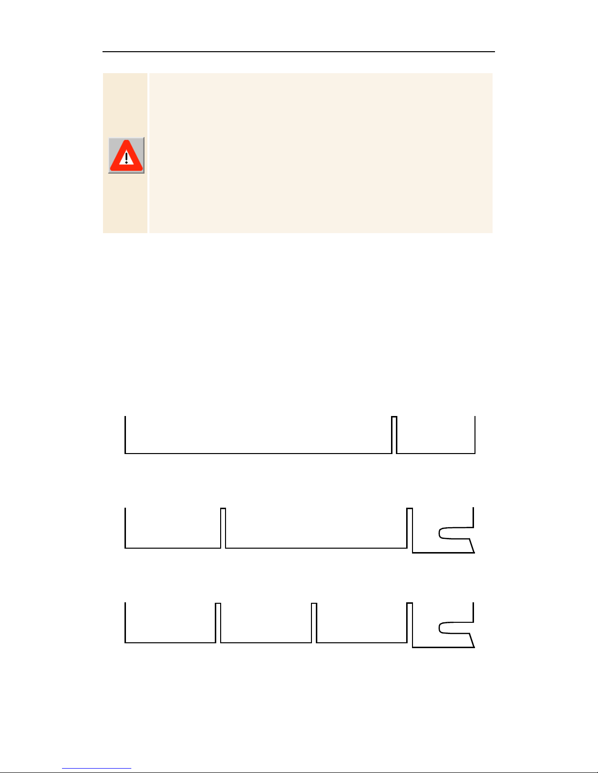
Installing the Hardware
Now that you have prepared your computer, you are ready to
install your card. If y ou are not sure whether you r card is PCI or
AGP, compare the bottom edge of your card with the following
illustration:
PCI
AGP 2x
Universal AGP 2x/4x
Page 13
Installing the Hardware and Software 13
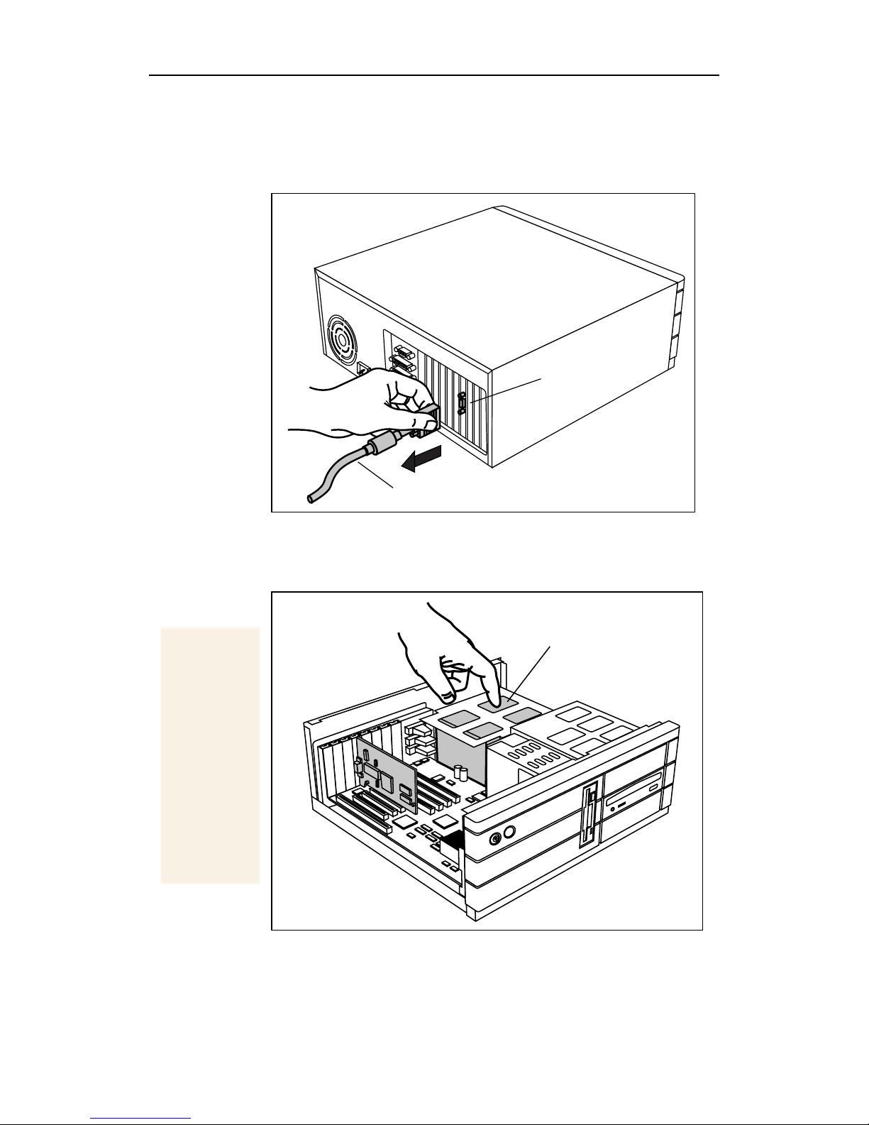
To install your card
1
2
Power-off the computer and monitor
the monitor cable
Remove the computer cover
computer system manual about removing the cov er.
from the back of your computer.
MONITOR CABLE
. If necessary, consult your
, then
VIDEO OUTPUT
CONNECTOR
disconnect
Remember
to
discharge
your body’ s
static
electricity
by touching
the metal
surface of
the
computer
chassis.
POWER SUPPLY
Page 14

14 Installing the Hardware and Software
If you intend to run multiple displays with Windows® 98
3
If the old
graphics
card sticks,
rock it
gently from
end to end.
Remember
to save the
screw .
(see Multiple Display Support in Windows® 98 on
page 38), proceed to step 4.
existing graphics card
SCREW
OLD GRAPHICS CARD
Otherwise, remove any
from your computer.
4
Grasp the
new card
by the top
edge and
carefully
seat it
firmly into
the correct
slot (PCI or
AGP).
Ensure that
the metal
contacts
are
completely
pushed into
the slot.
Or, if your computer has any
capability
, you may need to
on-board graphics
disable
it on the motherboard.
For more information, see your computer documentation.
If necessary, remove the metal cover from the empty
expansion slot that you select (PCI cards use a PCI slot;
AGP cards use the AGP slot), then
align your new card
with an empty expansion slot, and press it in firmly
until fully seated
ALL-IN-WONDER 128
(PCI or AGP) or
ALL-IN-WONDER 128 PRO
(AGP)
PCI EXPANSION SLOT
.
AGP EXPANSION SLOT
Note:
or AGP 2x slots.
AGP 4x/2x cards can be used in either AGP 4x
Page 15
Installing the Hardware and Software 15
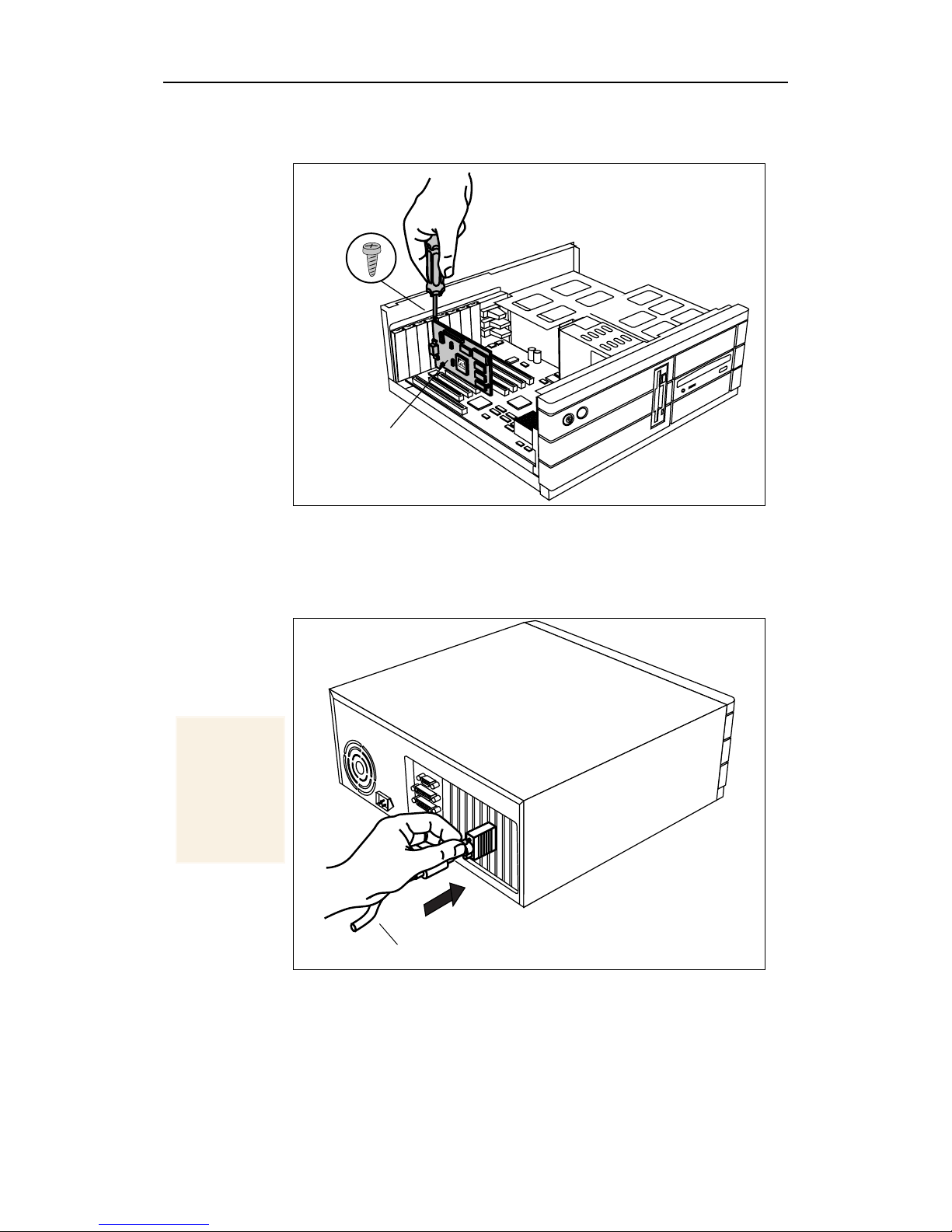
5
6
Replace the screw to fasten the card in place
the computer cover.
SCREW
ATI 3D GRAPHICS
CARD
Plug the monitor cable into y our card
multiple disp lays under Windows
to the appropriate connectors), then
and monitor(s)
.
®
(if you are runni ng
98, connect their cables
turn on the computer
, and replace
Make sure
your
monitor
cable is
securely
fastened.
MONITOR CABLE
ou are now ready to proceed with the installation of ATI’s
Y
enhanced drivers.
Page 16

16 Installing the Hardware and Software
Windows® “New Har dware Found”
If you are running Windows® 95 or Windows®98, ne w hardw are
may be detected after you restart your computer. Follow the
step-by-step instructions below to allow Windows
identify your new hardware.
®
to correctly
To identif y ne w hardware in
Windows® 95 briefly displays the “New Hardware Found”
1
dialog before launching the “Update Device Driver
Wizard”.
If the wizard does not appea r, proceed dir ectly to
Enhanced Drivers for Windows® 95 and Windows® 98
page 18.
Click
2
Click
3
Insert your Windows® 95 CD-ROM into your CD-ROM
4
drive.
Click
5
Type the following:
6
D:\WIN95
(If D is not your CD-ROM drive, substitute D with the
correct drive letter.)
Next
.
Finish
OK
.
.
Windows®95
Installing
on
Click
7
Click
8
You are now ready to install your ATI enhanced drivers.
Proceed to Installing Enhanced Drivers for Windows® 95 and
Windows® 98 on page 18, and follow the step-by-step
instructions to complete the installation.
To identif y ne w hardware in
After restarting your syste m, Windows® 98 will briefly display
the “New Hardware Found” dialog. Depending on your new
hardware, you will either be prompted to insert your Windows
98 CD-ROM or Windows
Hardware Wizard”.
OK
.
Yes
to restart your computer.
®
98 will launch the “Add New
Windows®98
®
Page 17

Installing the Hardware and Software 17
If W indo ws® 98 automatically begins installing drivers for your
new hardware, click
prompted; then proceed to Installing Enhance d Drivers for
Windows® 95 and Windows® 98 on page 18.
Yes
to restart your computer when
To identify new hardware using
Insert your Windows® 98 CD-ROM.
1
Click
2
Type the following:
3
D:\WIN98
(If D is not your CD-ROM drive, substitute D with the
correct drive letter.)
Click
4
Click
5
You are now ready to install your ATI enhanced drivers.
Proceed to Installing Enhanced Drivers for Windows® 95 and
Windows® 98 on page 18, and follow the step-by-step
instructions to complete the installation.
To identif y ne w hardware using “
Wizard
OK
.
OK
.
Yes
to restart your computer.
”
Windows®98 CD-ROM
Add New Har dware
Windows® 98 launches the “Add New Hardware Wizard”,
1
which prompts you to search for the Standard PCI Graphics
Adapter (VGA).
Click
2
Select
3
Click
4
Click
5
Click
6
(VGA).
Click
7
Click
8
You are now ready to install your ATI enhanced drivers.
Proceed to Installing Enhanced Drivers for Windows® 95 and
Windows® 98 on page 18, and follow the step-by-step
instructions to complete the installation.
Next
to continue.
Search for the best driver for your device
Next
to continue.
Next
to start the driver search.
Next
to install the Standard PCI Graphics Adapter
Finish
Yes
.
to restart your computer.
.
Page 18

18 Installing the Hardware and Software
Installing Enhanced Drivers for Windows®
95 and Windows® 98
With W indows®95 or Windows® 98 running on your computer,
you need to install the enhanced ATI drivers to take advantage
of your card’s higher performance, resolutions, and special
features. To ensure that you install the latest drivers, install the
ATI enhanced drivers located on the CD-ROM shipped with
your graphics accelerator card.
•
Close all open applications
your ATI software.
• Before installing the ATI enhanced drivers,
ensure that an y previo usly-installed A TI dis play
Notes
drivers ha ve been
To do this:
1
My Computer
. In
then double-click
2
. Click
Add/Remove
• Always use the
Installation CD-ROM to install ATI display
drivers and multimedia software.
The last three digits of the CD part number
represent the version — a higher number
indicates a later version.
• All ATI Installation CD-ROMs include a
complete set of displa y drivers an d multimedi a
software.
ATI Display Driver
removed
, double-click
Add/Remove Programs
.
latest version
To install the ATI enhanced drivers
for Windows
®
95 or Windows®98
before installing
from your system.
Control Panel
.
, then click
of the ATI
,
1
Insert the ATI INSTALLATION CD-ROM into your
CD-ROM drive.
If Windows
step 6.
2
Click
3
Select
4
Type the following:
D:\ATISETUP
(If D is not your CD-ROM drive, substitute D with the
correct drive letter.)
Start
Run
®
runs the CD-ROM automatically, proceed to
.
.
Page 19

Installing the Hardware and Software 19
5
Click
6
Click
7
Click
8
Click
9
Follo w the Wizard’s on-screen instructions to complete the
installation.
The
ATI product includes a
software for that component will
installed, along wit h the A TI enhanced dr ivers, by select ing
this option.
10
When the
applicable region, then click
11
When the
restart your computer, remove the ATI INSTALLATION
CD-ROM, then click
OK
.
ATI Easy Install
Next
.
Yes
to accept the license agreement.
Express
installation opti on is recommended. If yo ur
Select DVD Region
Setup Complete
to begin the Installation Wizard.
multimedia
Next
screen appears, click
Finish
.
component, the
automatically
screen appears, choose the
.
be
Yes
to
The first time you restart your computer, more drivers will
automatically be installed.
For correct r esolution an d refresh rate oper ation, you need
to select a
palette
colors. ATI r ecommends at least “High Color (16-bit)” for
best performance with its multimedia applicatio ns.
To increase the number of color s
1
Right-click on a clear area of your desktop, then click
Properties
2
Click
If you are using multiple monitors, click the monitor icon
whose color depth you want to change. If you click a
secondar y monitor and
this monitor
monitor’s settings.
display device
from 256 colors (the default) to a higher number of
.
Settings
.
is not checked, you cannot change that
. You should also ch ange t he
Extend my Win dows desktop on to
color
Each monitor has its own color settings.
3
In the
(24 bit)
Your type of monitor and video adapter determine the
maximum number of colors.
Colors
or
box, select
True Color (32 bit)
High Color (16 bit), True Color
.
Page 20

20 Installing the Hardware and Software
The RAGE 128 display drivers on your ATI Installation
CD-ROM are the latest and fastest available, but at ATI, we are
constantly impro ving ou r pr oducts, s o check the ATI web site at
http://www.atitech.ca
for newer software.
1
Click
2
Click
Supported
Drivers downloaded from the ATI website:
• Double-click the self-extracting executable file to start the
installation.
Note
North America
Drivers / Updates
.
Windows will auto ma tic al ly reboot your system
after the drivers are installed.
Europe
or
, then click
.
Retail Generic -
Starting the ATI Multimedia Cente r
in Windo ws® 95 or Windows® 98
From LaunchP ad
to start all your Multimedia Center features—just click the one
you want. LaunchP a d open s au tomati cal ly when y ou s t art yo ur
computer, or if you prefer, you can right-click LaunchPad, and
uncheck
this feature.
Load on Startup
. The LaunchPad pr o vid es a co nvenient way
in the drop-down menu to disable
From Windows
1
In the Windows taskbar, click
2
Point at
3
Point at
4
Click TV,
For informa tion on the ATI Multimedia Center, see the
online help.
®
taskbar
Programs
ATI Multimedia
Video Editor, CD Audio, DVD, or Video-CD
.
.
.
Start
.
.
Page 21

Installing the Hardware and Software 21
Input and Output Adapters
Your ALL-IN-WONDER 128 or ALL-IN-WONDER 128 PR O
card uses input and output adapters that let you connect audio
and video devices to the card. You can use these adapters to:
• Connect a VCR, laserdisc player, or camcorder, and watch
movies on your PC.
• Connect your camcorder and capture video for use in
presentations, Web pages, or use third-party
videoconferencing software.
• Connect your big-screen TV, and share the PC experience
with a group of peop l e, or play games on your big-screen TV.
• Attac
h a VCR to the video
games, internet, etc.
• To hear sound when you use your ALL-IN-
Notes
• For information on the CD audio connectors
CD audio
CD audio
connectors
connectors
A/V IN
A/V IN
CATV —
CATV
A/V OUT
A/V OUT
monitor
monitor
connector
monitor
connector
output and record presentations,
WONDER 128 family card’s TV feature, ensure
that your card is connected to the
connector of your sound card: see
see
page 48
ALL-IN-WONDER 128
SDRAM Memory
16MB or 32MB
non-upgradable
ATI RAGE 128 GL
Graphics Accelerator
line-in
page 24
.
Page 22

22 Installing the Hardware and Software
Notes
CD audio
ALL-IN-WONDER 128 PRO
CD audio
connectors
connectors
A/V IN
A/V IN
CATV
CATV —
A/V OUT
A/V OUT
monitor
monitor
monitor
connector
connector
ATI RAGE 128 PRO
Graphics Accelerator
Macrovision
Please note that the ALL-IN-WONDER 128 and
ALL-IN-WONDER 128 PRO detect Macrovision on an input
video source, and will refuse to capture video from such a
source. Many VHS tapes and DVD discs are protecte d with
Macrovision, which protects them from being copied onto your
computer using the ALL-IN-WONDE R 128 or ALL-IN-WONDER
128 PRO.
SDRAM Memory
32MB
DVD audio output
The ALL-IN-WONDER 128 family of cards
supports Dolby ProLogic™ output for connection to a surroundsound system through the standard stereo output connection
from your sound card. The ALL-IN-WONDER family does not
support S/PDIF digital audio output at this time.
Page 23

Installing the Hardware and Software 23
To watch movies on your PC or capture
video from your VCR, camcorder, or laserdisc play er
Use the ATI input adapter to connect a VCR, camcorder, or
laserdisc player to your ALL-IN-WONDER 128 or ALL-INWONDER 128 PRO, as shown.
The audio and video
output
connectors on your VCR, camcorder, or
laserdisc player will be similar to these. Use composite video out or
s-video out. S-Video will provide better results.
S-VIDEO
OUT
COMP.
VIDEO
OUT
L. AUDIO
OUT
R. AUDIO
OUT
Cable with
S-Video
plug at
each end,
available
OR
separately
from a
consumer
electronics
dealer.
SLR
A/V IN
CATV
AT I INPUT ADAPTER
(Enlarged here for clarity)
A/V OUT
ALL-IN-
WONDER
128 or
ALL-IN-
WONDER
128 PRO
Page 24

24 Installing the Hardware and Software
To display your PC output on TV
and record y our PC output on videotape
Use the output adapter to connect a TV, camcorder, or VCR to
your ALL-IN-WONDER 128 or ALL-IN-WONDER 128 PRO,
as shown.
The audio and video
input
connectors on your TV, camcorder, or VCR
will be similar to th es e . Use
will provide better results.
R. AUDIO
IN
L. AUDIO
IN
COMP.
VIDEO
IN
OR
Cable with RCA
plug at each end,
available separately
from a consumer
electronics deal er.
COMPOSITE VIDEO IN
S-VIDEO
IN
Cable with S-Video plug at each
end, available separately from a
consumer electronics dealer.
or S-
SOUND
CARD
VIDEO IN
output
adapter
. S-Video
A/V IN
CATV
A/V OUT
LINE IN
ALL-IN-
WONDER
128 or
ALL-IN-
WONDER
128 PRO
Page 25

Installing the Hardware and Software 25
Windows® 95 / Windows® 98 Volume Control
For correct audio performance, your sound card’s line input
must be active. To display the Line Input setting in the
Wi ndows 95
1
Right-click the speaker icon in the Taskbar (usually in
the lower-right corner of your screen).
®
/ Windows® 98 Volume Control panel:
2
Click
3
If the Line-In volume slider is not visible, click
then click
4
Click the
OK
•If the
Open Volume Controls
.
Options
Properties
Line-In
.
volume control checkbox, then click
.
Mute
checkbox is checked, click it to cancel muting.
If the speaker icon is not in your Taskbar, do the
following:
• In the Windows taskbar, click
Settings
• Double-click
• In the
Taskbar
, then click
Multimedia
Audio
tab, check
.
Control P anel
.
Show volume control on
Start
, point to
.
,
To select the sound card connector for TV audio input
The sound card connector determines which mixer slider is
controlled by the ATI Multimedia Center’s volume slider.
1
panel, then click the
2
Click the
three times to open the TV Sound Initialization Wizard.
3
Click the audio input that matches the connection between
your ATI card and your sou nd card. If you are not s ure how
it is connected, click each source (CD Audio, Line-I n, etc.),
and listen for the sound.
Click the Setup button in the TV Player control
Display
Initialization
tab.
button, then click the
Next
button
Page 26

26 Installing the Hardware and Software
TV reception tips
• In the TV T uner tab, en sure that you click the
for cable or antenna
.
• For the best indoor antenna reception, use an
model, and move it as
far away from your moni tor
correct setting
amplified
possible.
• If you experience problems with cable input, a signal
amplifier may improve reception.
as
Page 27

CHAPTER 3
Using Your
ALL-IN-W ONDER 128 or
ALL-IN-W ONDER 128 PRO
For comprehensive information on your card’s m ultimedia
features, please see the Using Your ATI Multimedia Center
User’s Guide that came with your card.
27
IN THIS CHAPTER...
Attaching a TV to Your Card
■
on page 28
Using TV Out
■
Connecting your PC to a
■
television or a VCR
Using SCART connectors for
■
European televisions
page 32
on page 29
on page 30
on
Page 28

28 Using Your ALL-IN-WONDER 128 or ALL-IN-WONDER 128
Attaching a TV to Your Card
Using your ALL-IN-WONDER 128 family card, you can
connect a televis ion set as your computer’s display . You can use
your card to do the following:
• View computer output directly on your television in either
NTSC or PAL formats (depending upon the country where
you purc hased your card)
• Connect using Composite or S-Video output capabilities
• Display images on both the TV and PC monitor
simultaneously
• Provide a big-screen e xperien ce for entertain ment PCs that is
ideal for playing games, giving presentations, watching
movies, and browsing the Internet
To connect your graphics card to a television
1
Turn off your computer and your television.
2
Determine if your television has an S-Video connection or
an RCA video-in connection.
3
Looking at the back of your computer, locate your graphics
card (see diagram below).
Card Connectors
A/V IN
CATV
A/V OUT
Composite video, S-Video and
audio input adapter connection
Cable or TV antenna input
Composite video, S-Video, and
audio output adapter connection
Graphics connector to monitor
4
Connect the supplied output cable adapter to the A/V OUT
connector on the card.
5
Using a cable with either S-Video or RCA connectors,
attach one end of the cable to the output cable adapter and
the other to your telev i sion.
Page 29

Using Your ALL-IN-WONDER 128 or ALL-IN-WONDER 128 PRO 29
6
Turn on your computer and your television.
If there is no display, you may need to enable the television
output capability; see Using TV Out.
detailed cablin g di ag ra ms and audio conn ectio ns
For
, see
Input and Output Adapte r s on page 21.
Note
Using TV Out
Television display is ideal for playing games, giving
presentations, watching movies, and bro wsing the Internet. The
following tips will help you get the most out of your TV Out
feature.
Some PC monitors in Europe
simultaneously with television display. When you enable
televisio n displa y in Europe , the refresh r ate f or the monitor
and television is set to 50Hz. Some monitors may not
support this refresh rate and could be damaged.
• Please check the documentation supplied with your
monitor to see if y our mo nitor su pports a refresh r ate of
50Hz.
If your monitor does not su pport 50 Hz (or if you are
not sure), then turn off your monitor before turning
on your computer when using your television as a
display.
You must attach a TV before enabling TV output.
IMPORTANT INFORMATION
for Eur opean Customers
cannot
be used
For information on disabling television display, see
enable and disable the television display on page 32
Some televisions in Europe may use an SCART
connection. If you use SCART, please read
connectors for European televisions on page 32
attempting to connect your PC to your television.
To
.
Using SCART
before
Page 30

30 Using Your ALL-IN-WONDER 128 or ALL-IN-WONDER 128
Connecting your PC to a televi sion or a VCR
To connect your computer to a television or a VCR, attach a
connector cable from the television (or VCR) to your card.
Most televisions and VCRs have a Composite video input, also
referred to as a phono jack or RCA input. A gro wing numb er of
televisions and VCRs have another type of video input called
S-Video or S-VHS. An S-Video connection produces a higher
quality display than Composite video.
If your television has cable input only, which is the case on
older units, you can connect your graphics card to your
television using your VCR or an RF modulator (available in
most electronics stores).
To connect your TV Out
graphics card to a television or VCR
1
Turn off your computer and your television or VCR.
2
Ensure your graphics card is installed correctly .
To use television display, you need the enhanced ATI
driver (version 6.00 or gre at er) installe d on your system.
For informa tion about placing the card in your computer
and installing the enhanced ATI driver, see the
Started…
3
Determine if your television or VCR has an S-Video or
Composite video connection.
4
Looking at the back of your computer, locate your graphics
card. Using an S-Video or Composite cable, attach one en d
of the cable to your graphics card and the other to your
television or VCR. (See the illustration, Connecting your
ATI graphics card to a TV or VCR on page 31.)
5
Turn on your computer and your television or VCR.
6
To turn your television display on and off, please see To
enable and disable the television display on page 32.
If there is no display on your television, you may need to
switch your television to video display. Fo r more
information, see the documentation supplied with your
television.
chapter.
Getting
If you have a television connected to your VCR, you can use
the television as your computer’s display. For information
about connecting a television to your VCR, see the
documentation that came with your VCR.
Page 31

Using Your ALL-IN-WONDER 128 or ALL-IN-WONDER 128 PRO 31
The audio and video
input
connectors on your TV or VCR will
be similar to these. Use composite video in or s-video in.
S-Video will provide better results.
R. AUDIO
IN
L. AUDIO
IN
COMP.
Cable with
RCA plug at
each end,
available
separately
from a
consumer
electronics
dealer.
VIDEO
IN
OR
S-VIDEO
IN
Cable with S-Video plug at each
end, available separately from a
consumer electronics dealer.
output
adapter
SOUND
CARD
A/V IN
CATV
A/V OUT
LINE OUT
To record audio on your stereo
LINE IN
VCR, use a stereo cable with two
RCA plugs at one end, and a mini
stereo phone plug at the other,
available separately from a
consumer electroni cs deale r.
Connecting your ATI graphics card to a TV or VCR
ALL-IN-
WONDER
or
128
ALL-IN-
WONDER
128 PRO
Page 32

32 Using Your ALL-IN-WONDER 128 or ALL-IN-WONDER 128
Using SCART connectors f o r European televisions
Right = Red)
Audio In
Connect to
TV or VCR
(
(Left = White)
Connect to
audio so urce
Cable 1
SCART
Connector
Using an SCART connector with a Composite cable
Video In (Yellow)
The SCART connector supports only the Composite video
format, which is the most common type. The above illustration
shows how to connect to an SCART connector with a
Composite cable.
If your television supports S-Video (also called S-VHS) video
input, you should use an S-Video cable (available in most
consumer electronics stores) to view your PC on a television.
An S-Video connection produces a higher quality display than
Composite video.
Using and Adjusting TV Out
To enable and disable the television display
Cable 2
Connect to
graphics card
1
Start Windows®.
2
Click
3
Point to
4
Double-click
5
Click the
W in dow s
the
6
Click the green
“TV” to enable/disable television display.
7
Click
For information about how to use television display and the
ATI Displays Properties page, click the
Start
.
Settings
Display
ATI Displays
®
98 users click the
ATI Displays
OK
or
Apply
, then click
Control Panel
.
.
tab.
Advanced…
button, then click
tab.
enable/disable
button next to the word
to save the changes you have made.
Help
button.
Page 33

Using Your ALL-IN-WONDER 128 or ALL-IN-WONDER 128 PRO 33
Starting Windows® with Television Displa y Enabled
The television screen may become scrambled temporarily
during the initial Windows
temporary effect, and your television screen will be restored
within a few seconds.
During start up, your TV Out graphics card will go through a
sequence of mode settings , during w hich y our tele vis ion disp lay
will remain blank. This process takes only a few seconds and
helps program the television displa y.
®
logo display. This is only a
Using a Monitor vs. Using the Television Display
Using your television for your computer’s display is ideal for
playing games, givin g presentations, watching movies, and
browsing t he Inte rnet. The di splay on your mon itor may ch ange
or look squashed. This occurs because the display adjusts to fit
the dimensions of your television. To correct the monitor’s
display , use the controls on the monitor to adjust the display size
and position.
Some single-frequency monitors may not work with television
display enabled. If you experience problems when television
display is enabled, disable television display to restore your
monitor’s display.
Adjusting the Monitor Display
The size of t he display on your monit or may be smal ler and not
perfectly centered when you have television display enabled.
These effects are caused by the changes required to provide a
proper display on the television.
Use the controls available on the Adjustments tab on the
Monitor Properties page (click the
Displays page) to adjust the display on your monitor only. Click
Television
the
button to adjust the television display only.
Monitor
button on the ATI
Page 34

34 Using Your ALL-IN-WONDER 128 or ALL-IN-WONDER 128
Viewing Text on Te levision
Due to the different technology used in the manufacturing of
televisions and PC monitors, standard PC text may look too
small on your television. You can compensate for this by using
larger fonts.
To Use Larger Display Fonts
1
Start Windows®.
2
Click
3
Point to
4
Double-click
5
Click the
6
In the
displayed fonts to be.
Windows
select your font size.
7
To customize the size of displayed fonts, select
Other
8
Click the
Yes
settings.
Start
.
Settings
Settings
Font Size
®
98 users click the
.
OK
button to restart your computer and use your new
, then click
Display
button, then click the
.
tab.
box, select the size you want your
Control Panel
Advanced…
Close
.
button then
Custom
button. Click the
or
Page 35

Using Your ALL-IN-WONDER 128 or ALL-IN-WONDER 128 PRO 35
Reducing Edge Distortion
When using a television for your PC’s display, you may see
some edge distor tion o n the left and right s ide o f your tel e visi on
screen. This effect depends on your television and the PC
application you are run ning. To reduce edge distortion, you can
increase the horizontal size.
To Increase the Horizontal Size
1
Start Windows®.
2
Click
3
Point to
4
Double-click
5
Click the
W in dow s
the
6
Click the TV button.
7
Click the
8
Click the plus (+) button under Horizontal Screen to
increase the horizontal size of the television display.
9
Click
You can also reduce edge distortion by reducing the brightness.
To change the brightness
1
Start Windows®.
Start
.
Settings
Display
ATI Displays
®
98 users click the
ATI Displays
Adjustments
OK
or
Apply
, then click
.
tab.
to save the changes you have made.
Control Panel
tab.
Advanced…
tab.
.
button, then click
2
Click
3
Point to
4
Double-click
5
Click the
W in dow s
the
6
Click the TV button.
7
Drag the
brightness.
8
Click
Start
.
Settings
Display
ATI Displays
®
98 users click the
ATI Displays
Brightness slider
OK
or
Apply
, then click
.
tab.
to save the changes you have made.
Control Panel
tab.
Advanced…
to the left to decrease the
.
button, then click
Page 36

36 Using Your ALL-IN-WONDER 128 or ALL-IN-WONDER 128
Changing Display Configurations
If you move your computer to a place where you are using
television display only, make sure that you have the television
display feature enabled first; see To enable and disable the
television display on page 32.
Using Games and Applications
Some older games and applications may program the graphics
card directly to run under a specific display mode. This may
cause your television display to turn off automatically or
become scrambled (the PC monitor will not be affected). Your
television display will be restored once you exit the game or if
you restart your system.
Page 37

37
CHAPTER 4
For Windows® 98 Users...
Windows® 98 offers many exciting new features for users with
an ALL-IN-WONDER 128 or ALL-IN-WONDER 128 PRO.
IN THIS CHAPTER...
Multiple Display Support in
■
Windows® 98
on page 38
WebTV® for Windows
■
NetMeeting™ 2.1
■
on page 39
on page 40
Page 38

38 For Windows® 98 Users...
Multiple Display Support in Windows® 98
Windows® 98 provides suppo rt for usi ng more th an one displ ay
device at a time—you simply ins tall a separate PCI or AGP card
for each additional monitor you intend to use. With multiple
displays, you can expand your desktop, run different programs
on separate displ ays, even play some newer games with
multiple views. Each display can have a different resolution and
color depth!
You can use multiple monitors
same time.
Windows
primary
designated as a
®
98 automatically designates one graphics card as the
graphics card. Each additional graphics card is
secondary
card. Certain 3D and multimedia
features are only a vailable o n the
a single television at the
and
primary
graphics card. If you
are installing more than one graphics card, you need to consider
the following:
• If you install both a
same system, the
secondary
• If you install
graphics card.
two or more PCI
PCI and an AGP
AGP
graphics card will become the
graphics card in the
graphics cards in the same
system, the primary graphics card is typically the one
installed in the PCI slot with the lowest number—this is
typically the PCI slot farthest f rom the computer’s ISA slots.
Consult your comp ut er s yst em manu al for help in selecting a
slot.
The latest information on installing ATI’s cards and enhanced
drivers for Windows
ATI Installation CD-ROM.
N
OTE
®
98 is provided in the Readme file on the
Some motherboards will allow an
as the
flash BIOS (for example, ASUS, Intel) may be
required to enable this feature. Check your
motherboard manufacturer’s website for
information.
primary
graphics card. A mother board
card to act
AGP
Page 39

WebTV® for Windows
For Windows® 98 Users... 39
North
American
feature
The ALL-IN-WONDER 128 family’s advanced TV Tuner
capabilities are a perfect match for Windows
®
98’ s ne w WebTV
interface. Use your Internet connection to instantly download
television program information for current and future shows.
If you do not ha v e an Intern et connection, you can do wnload the
same program information over a cable connection! WebTV
puts you in control of your TV scheduling, and allows you to
navigate interactive programming — never miss your favorite
show!
To enjoy WebTV on your ALL-IN-WONDER 128
family-equipped PC, you mu st use the
N
OTE
later display drivers
Windows will automatically reboot your system
after the drivers are installed.
.
To install WebTV on y our Windows
1
In the Windows taskbar, click
Start
®
98 system
.
ATI 6.00 or
2
Point at
3
Double-click the
4
Click the
5
Double-click the
Settings
Windows
, and click
Control Panel
Add/Remove Prog rams
Setup tab.
Web TV for Windows
.
icon.
item.
Ensure that both WaveTop Data Broadcasting and WebTV
for Windows are checked.
6
Click
OK
, and allow Windows® 98 to install the new
components.
You will want to use the ATI Mult im edia Ce nter for advanced
features such as Instant Replay and video capture, and WebTV
to access interactive program guides and interactive web
content.
WebTV and the ATI Multimedia Center cannot be
N
OTE
used at the same time; you must close one before
running the other.
Page 40

40 For Windows® 98 Users...
NetMeeting™ 2.1
Wi ndows® 98’s NetMeeting 2.1 provides a single interface for
multipoint data conferencing and collaboration on virtually any
Windows-based application, in addition to high quality
videoconferencing ov er a LAN or the Internet. All you need is a
video camera that supports composite or S-Video out: plug it into
your ALL-IN-WONDER 128 family card’ s video input port, and
you’ll be ready to use your comp uter as an Internet video -phone!
To set up Microsoft NetMeeting on your computer
1
In the Windows taskbar, click
2
Point at
and click
The NetMeeting install wizard will guide you through
several simple steps, and ask you which capture driver you
would like to use. Select the driver labeled
VfW MM 16-bit WDM capture driver
N
OTE
Programs
Microsoft NetMeeting
You must use the Windows 98 or RAGE 128
display drivers with Net-Meeting.
, then point at
Start
.
Internet Explorer
.
.
,
Page 41

CHAPTER 5
Tips and Tricks
This chapter suggests some exciting new ways to use your
ALL-IN-WONDER 128 or ALL-IN-WONDER 128 PRO. You
will need to attach a video camera to your card, following the
instructions on page 23.
Many camcorders and digital cameras have composite or
S-Video outputs that will provide real-time images on your
card. Using the ATI Multimedia Center’s Digital VCR feature,
you can capture them as still frames and full-motion clips.
41
IN THIS CHAPTER...
Video Email
■
Stop-Motion Animation
■
Security Camera
■
on page 42
on page 43
on page 42
Page 42

42 Tips and Tricks
Video Email
Use your ALL-IN-WONDER 128 or ALL-IN-WONDER 128
PRO to capture a video clip, which you then attach to an email
message for your family and friends.
Because video files can be very large, you should use a small
capture size – 240x160 or smaller – and the card’s video
compression features to reduce the file size (see Capturing
video and still images in the Using Your ATI Multimedia Center
User’s Guide).
Indeo 3.2
•
or
4.1
are popular compression codecs (encoderdecoders) that can dramatically reduce the file size while
maintaining good quality. Any Windows 95 / Windows 98
system will play Indeo 3.2.
• If you use the
ATI VCR 1.0
or
2.0
codec to compress your
video on-the-fly , you must ensure that the recei ving computer
can play these files back.
• MPEG-1 is also a standard format, which most Windows
and Macintosh
Note
computers can play.
Macrovision
Please note that the ALL-IN-WONDER 128 and
ALL-IN-WOND ER 128 PRO detect Macro vision on
an input video source, and will refuse to capture
video from such a source. Many VHS tapes and
DVD discs are protected with Macrovision, which
protects them from being copied onto your
computer using the ALL-IN-WONDER 128 or
ALL-IN-WONDER 128 PRO.
Stop-Motion Animation
Using the TV Player’ s
series of still shots and save them as an .AVI movie. You can
use this feature to easily produce a “claymation” or other workin-progress type of movie. See To record a sequence of frames
(stop-motion) in the Using Your Multimedia Center User’s
Guide.
sequence capture
feature, you can take a
Page 43

Security Camera
Your ALL-IN-WONDER 128 or ALL-IN-WONDER 128 PRO
provides an ideal way to capture video for an extremely long
period of time—no more worries about your security camera
running out of tape! Simply set your card to a lower video
capture frame rate, and capture many high quality still images
automatically, for days at a time. See Capturing video and still
images and Digital VCR settings in the ATI Multimedia Center
User’s Guide.
suggested settings
Tips and Tricks 43
Codec
Size
Frame rate
Streaming video
An improved security camera would stream the real-time video
feed from your card to the internet. Real Networks
(http://www.real.com) provides software to perform this.
ATI VCR 2.0
320x240
1 frame per second
™
Page 44

44 Tips and Tricks
Page 45

CHAPTER 6
Reference
This chapter contains troubleshooting tips and specif ications for
your ALL-IN-WONDER 128 or ALL-IN-WONDER 128 PRO.
45
IN THIS CHAPTER...
Troubleshooting Tips
■
page 46
Compliance Information
■
page 50
on
on
Page 46

46 Reference
Troubleshooting Tips
The following troubleshooting tips may help you if you
experience problems. Contact your dealer for more advanced
troubleshooting information.
Basic troubleshooting tips
• Check that the
If the problem still exists, try a different PCI expansion slot.
• Ensure that the
card.
• Make sure that the
receiving power
and
• For Windows
graphics capabilities
information, see your computer documentation.
• Make sure that you selected the
you installed your enhanced driver.
• If you use an indoor antenna, you will get the best results
with an
monitor
• Splitting the cable or antenna input can reduce the signal
quality. For the best reception,
antenna directly to your card
amplified
as possible, to avoid interference.
card is seated properly
monitor cable is securely fastened
monitor and computer are plugged in
.
®
95 / Windows® 98,
on your mother board. For more
appropriate monitor
model. Place it as
connect the cable or
.
in its expansion slot.
disable any bu i l t-in
far away from the PC
to the
when
• Make sure that your
Windows® 95 / Windows® 98 Volume Control on page 25).
audio card’s line input is active
(see
Page 47

Reference 47
Windows® 95 / Windows® 98 troubleshooting tips
For Windows® 95 / Windows® 98 troubleshooting tips, rightclick the ATI icon in the taskbar, and select
If you have problems during start-up, start your computer in
Safe Mode.
Troubleshooting
.
To load Windows
1
Turn on your computer.
2
In Windows® 95
®
95 / Windows® 98 in Safe Mode
, press the F8 key when Starting Wi ndows
95 appears on the screen.
In Windows
Windows 98 Startup Menu appears, then
number for Safe Mode
3
Select
Safe Mode
®
98
, press and hold the
, and press
.
CTRL
Enter
key until the
select the
.
• Disable any programs that launch automatically when
you start Windows
®
95 / Windows® 98.
• Check that you have the correct monitor and display
driver selected in the Display Properties. For more
information, click Help in the Start menu.
• Check for the existence of memory managers and ensure
they are configured properly.
• Refer to additional information in the Windows
Wi ndows
®
98 README file located in the root director y
on the ATI Installation CD-ROM.
®
95 /
If you don’t hear audio
card’s line input is active (see
Windows® 98 Volume Control on page 25
, make sure that your audio
Windows® 95 /
).
Page 48

48 Reference
CD Audio Connectors
The following illustration shows the CD audio connectors on
your ALL-IN-WONDER 128 or ALL-IN-WONDER 128 PRO
card.
CD OUT
pins 2 and 4 (see the
connectors,
following tab le)
CD AUDIO IN
(see your sound card
J1 J2
CD
OUT CD IN
ALL-IN WONDER 128 / ALL-IN-WONDER 128 PRO
connectors
manual)
SOUND
CARD
(Not a vailable on all versions)
ALL-IN-WONDER
This table lists
the pin
assignments
for the CD
audio
connectors on
your card.
ALL-IN-WONDER
128 FAMILY CARD
J2 CD IN Pin 1 - GND
J2 CD IN Pin 2 - LEFT IN
J2 CD IN Pin 3 - GND
J2 CD IN Pin 4 - RIGHT IN
J1 CD OUT Pin 1 - GND
J1 CD OUT Pin 2 - LEFT OUT
J1 CD OUT Pin 3 - GND
J1 CD OUT Pin 4 - RIGHT OUT
SIGNAL PIN
Page 49

Reference 49
To Remove the ATI Multimedia Center
1
In the Windows taskbar, click
2
Point to
3
Click
4
Double-click
5
Select
6
Click
7
Click
Settings
Control Panel
ATI Multimedia Center
Add/Remove...
OK
.
.
Add/Remove Prog rams
.
Start
from the list.
Japanese Users Please Note ...
• Stereo TV and Secondary Audio Program (SAP) are not
availalable in Japanese versions of the TV Player.
.
.
Page 50

50 Reference
Compliance Information
FCC Compliance Information
The ALL-IN-WON DER 128 f amily of c ards complies with FCC
Rules Part 15. Operation is subject to the following two
conditions:
• This device may not cause harmful interference, and
• This device must accept any interference received,
including interference that may cause undesired
operation.
This equipment ha s been te sted and foun d to comply wit h the l imits fo r
a Class B digital device, pursuant to Part 15 of the FCC Rules. These
limits are designed to provide reasonable protection against harmful
interference in a residential insta llation. This equipme nt generates, uses
and can radiate radio frequency energy and, if not installed and used in
accordance with manufacturer's instructions, may cause harmful
interference to radio commun ications. However, there is no guarantee
that interference will not occur in a particular installation. If this
equipment does cause harmful interference to radio or television
reception, which can be determined by turning the equipment off and
on, the user is encouraged to try to correct the interferen ce b y one or
more of the following measures:
• Re-orient or relocate the receiving antenna.
• Increase the separati on between the equipment and receiver.
• Connect the equipment to an outle t on a circuit diffe rent from that to
which the receiver is connected.
• Consult the dealer or an experienced radi o/TV technician for help.
• The use of shielded cables for connection of the monitor
to the graphi cs card is require d to ensure complianc e with
FCC regulations.
• Changes or modifications to this unit not expressly
approved by the party responsible for compliance could
void the user's authority to operate this equipment.
Industry Canada Compliance Statement
ICES-003 This Class B digital apparatus meets all requir ements of the
Canadian Interference-Causing Equipment Regulations.
Cet appareil numérique de la Classe B Respecte toutes les
exigences du Rè g le ment su r le matérial brou ille r du Canada.
Page 51

Reference 51
CE Compliance Information
EMC Directive 89/336/EEC and Amendment 92/31/EEC, Class B
Digital Device
EN 50081-1, Generic Emissions Standard for Residential, Commercial
and Light Industrial Products
(EN 55022/CI SPR 22, Limits and Methods of Measurement o f Radio
Interference Characteristics Information Technology Equipment)
Warning: This is a Class B product. In a domestic environment this
product may cause radio interference in which case the user may be
required to take adequate measures.
EN 50082-1, Generic Immunity Standard for Residential, Commercial
and Light Industrial Products
(IEC 801-2, IEC 801-3, IEC 80 1-4)
Directive EMC 89/336/CEE et amendement 92/31/CEE, dispositif
numérique de Classe B
EN 50081-1, Norme sur les émissions génér iques pour les produits
domestiques, commerciaux et industriels légers
(EN 55022/CISPR 22, Limites et méthodes de mesure des
caractéristiques d'interférences radiophoniques, Matériel des
technologies de l'information)
Mise en garde: ceci est un produit de
Classe B. Il risque produire des interférences radiophoniques dans un
environnement domestique auquel cas l'utilisateur peut se voir
demandé de prendre des mesures adéquates.
EN 50082-1, Nor me sur l'immunité générique pour produits
domestiques, commerciaux et industriels légers.
(CEI 801-2 , CEI 801-3, CEI 801-4)
EMC Richtlinie 89/336/EEC und Änderung 92/31/EEC, Digitales
Gerät der Klasse B
EN 50081-1, Allgemeiner Emissions-Sta ndard für Haus ha lt- und
kommerzielle Produkte sowie Erzeugnisse der Leichtindustrie
(EN 55022/CISPR 22, Beschränkungen und Verfahren der Messung
von informationstechnischen Ausrüstungen mit Funkstörmerkmalen)
Warnung: Dies ist ein Erzeugnis der Klasse B. Dieses Er zeugnis kann
Funkstörungen im Wohnbereich veru rsachen; in die s em Fall können
entsprechende Maßnahmen seitens des Benutzers erforderlich sein.
EN 50082-1. Al lge m e i ner Un emp findlichkeits-Sta n da rd f ür H aus ha lt-
und kommerziell e Produkte sowie Erzeugnisse der Leichtind ustrie
(IEC 801-2, IEC 801-3, IEC 80 1-4)
Page 52

52 Reference
Page 53

Index
A
AGP
12
10
8
50
20
49
22
31
23
22
48
19
19
23
24
22
19
4X, 2X
ALL-IN-WONDER family
compliance information
ATI Multimedia Center
opening in Windows 95/98
uninstalling
ATI Multimedia Center User’s
Guide
Audio
DVD audio output
recording on your VCR
C
Capturing video
macrovision
CD audio connectors
Color depth
increasing
Colors
increasing number of
Composite video
D
Displaying PC output on TV
Drivers
downloaded from ATI website
DVD
audio outpu t
Region Codes
20
I
Input and output adapters
displaying PC output on TV and
recording on videotape
watching movies on your PC and
capturing vi d eo
Installing the hardware and
software
input and output adapters
installing the hardware
M
Macrovision
Monitor
adjusting display
using a monitor vs. TV display
MPEG-1
Multiple display support in
Windows 98
N
NetMeetin g 2.1
O
Online Help
Online manual
P
PCI
PCI and AGP graphics cards
Primary and secondary graphics
cards
12
38
11
22, 42
33
42
38
40
9
10
23
12
21
21
24
38
33
R
Readme file
Recording PC output on videotape
24
Region Codes
Index - 53
9
19
Page 54

S
SCART connectors
Secondary Audio Program
stereo unavailable in Japan
Security camera
Sound card connector
selecting for TV audio input
Stop-motion animation
Streaming video
S-Video
System requirements
T
Tips and Tricks
Troubleshooting tips
TV
23
security camera
stop-motion animation
streaming vide o
video email
basic
46
Windows 95/98
attaching to ALL-IN-WONDER
128
28
displaying PC output on
reception tips
selecting soun d car d c onn e c tor for
TV audio input
TV Out
viewing text on
29
42
26
43
43
43
43
47
34
32
8
46
25
42
42
24
49
25
V
Video
39
38
30
23
25
composite video, S-Video
39
38
42
42
25
23
40
compressors
Video email
Volume control
W
Watching movies on your PC
Watching movies on your PC and
capturing video
WebTV for Windows
Windows 95/98 volume control
Windows 98
multiple display support
NetMeeting 2.1
primary and secondary graphics
cards
WebTV
Index - 54
Page 55

Safety instructions for TV tuner products
IMPORTANT SAFETY INSTRUCTIONS
•
Read Instructions
read before the product is operated.
•
Retain Instructions
retained for future reference.
•
Heed Warnings
instructions should be adhered to.
•
Compatibility
compatible UL Listed personal computers that have Installation
Instructions detailing user installation of card cage accessories.
•
Grounding
Electric Shock and Fire, This Accessory Should Be Installed Only In
Products Equipped With A Three-wire Grounding Plug, A Plug Having
a third (Grounding) Pin. This plug will only fit into a grounding-type
power outlet. This is a safety feature. If you are unable to insert the
plug into the outlet, contact your electrician to replace the obsolete
outlet. Do not defeat the safety purpose of the grounding-type plug.
• All option card securement pins shall be completely tightened as to
provide continuous bonding between the option card and the PC
chassis.
•
Outdoor Antenna Grounding
system is connected to the product, be sure that the antenna or cable
system is grounded so as to provide some protection against voltage
surges and built-up static charges. Article 810 of the National
Electrical Code, ANSI/NFPA 70, provides information with regard to
proper grounding of the mast and supporting structure, grounding of
the lead-in wire to the antenna discharge unit, size of grounding
conductors, location of antenna-discharge unit, connection of
grounding electrodes, and requirements for the grounding electrode.
•
Lightning
storm, or when it is left unattended and unused for long periods of time,
unplug it from the wall outlet, and disconnect the antenna or cable
system. This will prevent damage to the product due to lightning and
power-line surges.
•
Po wer Li nes
vicinity of overhead power lines or other light or power circuits, or
where it can fall into such power lines or circuits.
• When installing an outside antenna system, extreme care should be
taken to keep from touching such power lines or circuits, as contact
with them may be fatal.
•
Note to CATV System Installer
CATV systems installer’s attention to Section 820-40 of the NEC, which
provides guidelines for proper grounding and, in particular, specifies
that the cable ground shall be connected to the grounding system of
the building, as close to the point of cable entry as practical.
- CAUTION: For Continued Protection Against Risk of
- For added protection for this product during a lightning
- All the safety and operating instructions should be
- The safety and operating instructions should be
- All warnings on the product and the operating
- This option card is for use only with IBM AT or
- Since an outdoor antenna or cable
- An outside antenna system should not be located in the
- This reminder is provided to call the
i
 Loading...