

Page 1
DISTRIBUTION AMPLIFIERS
OPERATING AND MAINTENANCE MANUAL
www.atiaudio.com
DaySequerra
7209 Browing Road
© Copyright 2018, ATI is a registered trademark of DaySequerra Corp.
Pennsauken, NJ 08109 sales@daysequerra.com
www.atiaudio.com
Page 2

PRODUCT DESCRIPTION
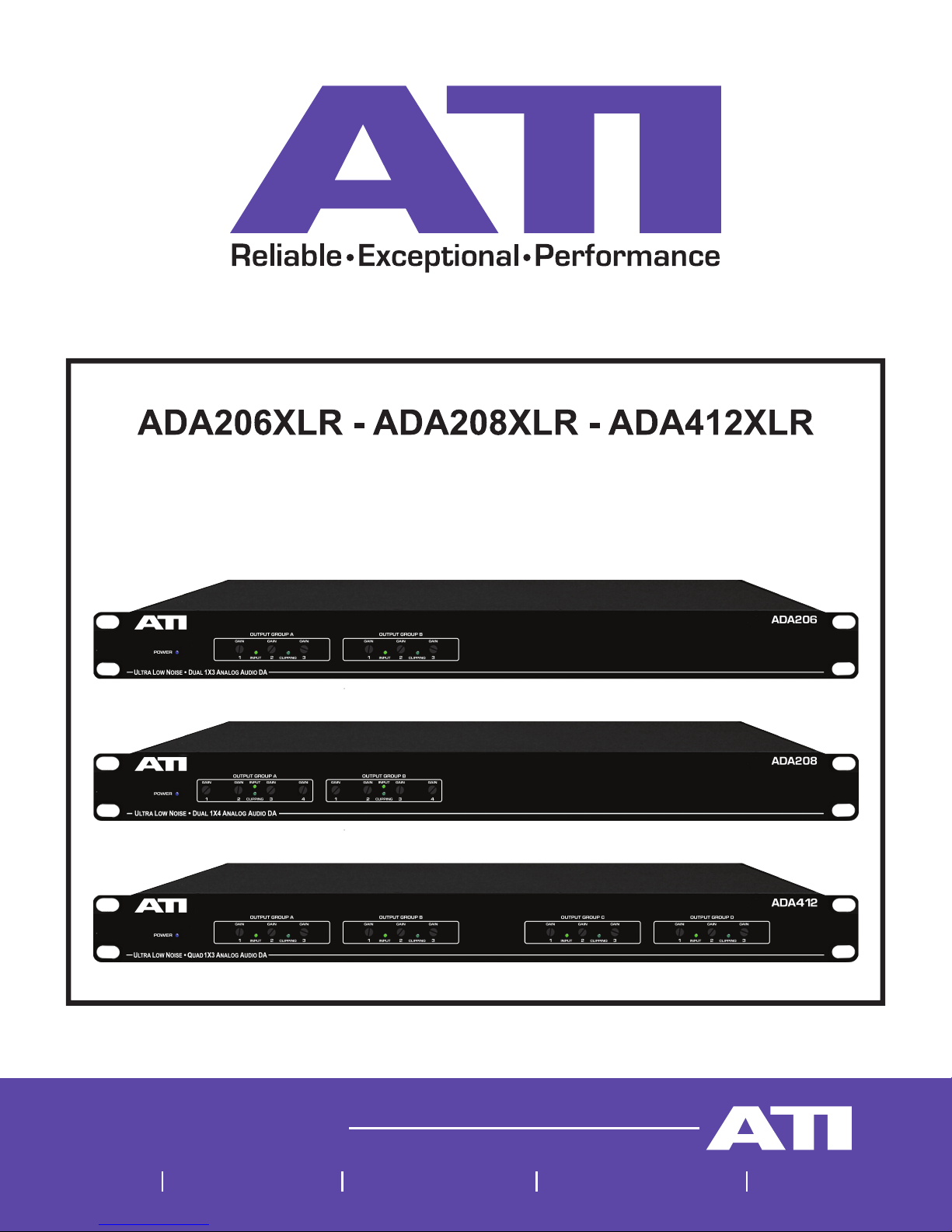
The ADA206XLR, ADA208XLR and ADA412XLR Analog Audio Distribution Amplifiers provide
two (206) or four (412) 1X3 distribution amplifier channels, and two (208) 1x4 distribution
amplifier channels, with balanced inputs and outputs. A master, gain adjustment for each
channel controls all three outputs together to adjust for varying inputs, while individual trimmers
for each output allow adjustment over a 20dB range to accommodate 10dbu semi-pro up to
+8dBm line levels.
Another of the ADA206XLR, ADA208XLR and ADA412XLR Distribution Amplifiers many
claims to fame is the use of XLR type input and output connectors. XLRs are easy to use but
make paralleling inputs for 1X6 or 1X12 operation difficult.
An LF347N quad bi-fet opamp forms the three variable gain output adjustment stages. These
variable gain stages use a unique circuit arrangement that allows us to provide a smooth,
logarithmic gain control for each output using an inexpensive (but good) linear cermet
potentiometer. Since we actually reduce the stage gain for low outputs rather than taking the
more conventional approach of reducing the input level to a fixed gain amplifier, you can use
the ADA at low output levels with very little noise penalty. You can use the ADA to match
consolemedium level inputs (-20dBu) or to drive semi-pro IHF inputs without requiring
outboard attenuator pads.
SSM2142 active balanced output drivers sense the voltage on their high and low output lines
and will shut off drive to a grounded output line while doubling the drive on the other. This
capability allows you to connect the outputs to balanced or unbalanced loads without regard
to whether or which side of the output is grounded. Maximum output at clipping is +22dBm into
balanced loads; however, even though the gain is the same under either condition, clipping
output is reduced by 6dB when driving an unbalanced load since the full output swing capability
of only one driver of the two is available.
The ADA family operates from a 15W – 24VDC single output switching supply featuring
universal AC input. Operating in the range of 85 – 264 VAC / 120 – 370 VDC, it offers low ripple
and noise at a max 150mV peak to peak.
www.atiaudio.com
DaySequerra
7209 Browing Road
Pennsauken, NJ 08109 sales@daysequerra.com
www.atiaudio.com
Page 3

INSTALLATION
The ADA is designed for rack mounting on standard EIA 1-3/4 inch centers. Each unit
dissipates approximately 10 watts and is designed for use in an office environment. Avoid
excessive heat buildup (such as might be due to nearby power amplifiers in unventilated racks)
to ensure maximum component life.
AUDIO CONNECTIONS
XLR inputs and outputs are wired with pins 2 as HI and pins 3 as LOW. Pin 1 (shield) of all
input and output connectors are permanently grounded in accordance with current AES
recommendations. The pin 1 grounds are routed via a large, low impedance ground path
directly to the chassis separately from any audio ground paths. Internal circuit ground is also
connected to the chassis for shielding through an independent path. AC ground (green wire) is
also separately grounded to the chassis. Active balanced outputs require a reference ground
connection to the receiving device for proper operation. This ground is carried through pin 1.
If the pin 1 shield ground is not carried through to the receiving device, the AC ground, rack
frame, or studio ground system may complete this ground. Noisy grounds require excellent
common mode rejection in the receiving device for quiet system operation.
We have taken measures to keep RFI out of your ADA, including split and bypassed input
networks, beaded, bypassed and isolated power inputs, nonconcentric wound, semi-toroidal
power transformers, double ground plane PC boards and a nice enclosure to keep rain and
snow off the circuit boards. However, in difficult broadcast applications, the RF shielding and
suppression system can be no better than the ground system into which it is trying to dump the
unwanted RF. For optimal product performance, be sure to have a good grounding system.
ADJUSTMENTS
The Master and individual Output level controls should all be set close to 2 o’clock to provide
nominal +4dBm outputs for a nominal +4dBu input. These settings allow +6/-16dB output
adjustment range around nominal, which will allow outputs of +10 to -12dBm to be set. In
addition, the Master gain has +10dB to OFF adjustment range to compensate for input level
variations from -6dBu to input clipping at +24dBu.
www.atiaudio.com
DaySequerra
7209 Browing Road
Pennsauken, NJ 08109 sales@daysequerra.com
www.atiaudio.com
Page 4

115VAC & 230VAC OPERATION
The ADA is ready for 115 VAC or 230 VAC. A single output switching power supply offers
protections from short circuit, overload, and over voltage while capable of accepting VAC in
the range of 85 – 264 VAC.
UL LISTING
The ADA206XLR, ADA208XLR and ADA412XLR are listed by Underwriter Laboratories as
“Listed Professional Audio Equipment 2D65.”
www.atiaudio.com
DaySequerra
7209 Browing Road
Pennsauken, NJ 08109 sales@daysequerra.com
www.atiaudio.com
Page 5

PRODUCT SPECIFICATIONS
OUTPUT LEVEL: +22dBm peak into 600 ohm balanced load, +18dBm peak, typical, into
unbalanced loads
DISTORTION: THD .10% maximum, 20 to 20,000Hz at peak output, IMD .05% maximum,
SMPTE measurement
SLEW RATE: 13 Volts per microsecond
RESPONSE: ± .25dB, 20 to 20,000Hz
NOISE: -95dBm out at maximum gain, 20kHz bandwidth
GAIN: 40dB maximum
CROSSTALK: 70dB minimum at 10kHz, any path
OUTPUT ISOLATION: 70 dB minimum at 1kHz. A shorted output does not affect any
other output.
OUTPUTS: Active balanced, servo controlled, ground sensing, 50 Ohm output impedance,
DC coupled. XLR type male connectors, Pin 2-HI, 3-LO, 1-GND.
INPUTS: 20Kohm active balanced, split and RF bypassed. +22dBm maximum input level,
60dB CMR at 60Hz. XLR type female connectors, Pin 2-HI, 3-LO, 1-GND.
POWER: 85-264 VAC ±1%, Output Voltage 24 VDC, Ouput Power 15 W, 47 - 63Hz
frequency range.
SIZE: 19” (48.3cm) W X 1.75” (4.45cm) H X 7.5” (19cm) D
www.atiaudio.com
DaySequerra
7209 Browing Road
Pennsauken, NJ 08109 sales@daysequerra.com
www.atiaudio.com
Page 6

SHIPPING WEIGHT & DIMENSION: 12 lbs. (5.5kg), 22”x12”x5”
MODELS AVAILABLE: ADA206XLR Dual 1X3 Active balanced outputs, ADA412XLR Quad
1X3 Active balanced outputs, ADA208XLR Dual 1X4 Active balanced outputs
ADA206XLR
ADA208XLR
ADA412XLR
www.atiaudio.com
DaySequerra
7209 Browing Road
Pennsauken, NJ 08109 sales@daysequerra.com
www.atiaudio.com
Page 7

ONE YEAR LIMITED WARRANTY
ATI warrants this product to be free from defects in materials and workmanship to its original
owner for a period of one year from date of purchase. ATI will repair or replace such product
or part thereof, which upon inspection by ATI, is found to be defective in materials or
workmanship.
The Proper Return Authorization Number must be obtained from ATI in advance of return.
Contact ATI at 856-719-9900 or email sales@daysequerra.com to receive the number and
instructions for return of your unit.
A written statement providing the name, address, daytime telephone number and email address
of the original owner, together with receipt from the original purchase, and a brief description
of any claimed defects, must accompany all returns. Parts or product for which replacement is
made shall become the property of ATI.
The customer shall be responsible for costs of transportation and insurance to the factory of
ATI, and shall be required to prepay such costs.
ATI shall use reasonable efforts to repair or replace any product covered by this limited
warranty within thirty days of receipt. In the event repair or replacement shall require more than
thirty days, ATI shall notify the customer accordingly. ATI reserves the right to replace any
product that has been discontinued from its product line with a new product of comparable
value and function.
This warranty shall be void in the event a covered product has been damaged, or failure is
caused by or attributable to acts of God, abuse, accident, misuse, improper or abnormal usage,
failure to follow instructions, improper installation or maintenance, alteration, or lightning, power
fluctuations and other incidental or environmental conditions. Further, product malfunction or
deterioration due to normal wear is not covered by this warranty.
www.atiaudio.com
DaySequerra
7209 Browing Road
Pennsauken, NJ 08109 sales@daysequerra.com
www.atiaudio.com
Page 8

ATI DISCLAIMS ANY WARRANTIES, EXPRESS OR IMPLIED, WHETHER OF
MERCHANTABILITY OF FITNESS FOR A PARTICULAR USE, EXCEPT AS EXPRESSLY
SET FORTH HEREIN. THE SOLE OBLIGATION OF ATI UNDER THIS LIMITED WARRANTY
SHALL BE TO REPAIR OR REPLACE THE COVERED PRODUCT, IN ACCORDANCE WITH
THE TERMS SET FORTH HEREIN. ATI EXPRESSLY DISCLAIMS ANY LOST PROFITS,
GENERAL, SPECIAL, INDIRECT OR CONSEQUENTIAL DAMAGES WHICH MAY RESULT
FROM BREACH OF ANY WARRANTY, OR ARISING OUT OF THE USE OR INABILITY TO
USE ANY ATI PRODUCT.
Some states do not allow the exclusion or limitation of incidental or consequential damages or
limitation on how long an implied warranty lasts, so the above limitations and exclusions may
not apply to you.
This warranty gives you specific legal rights, and you may also have other rights that vary from
state to state.
ATI reserves the right to modify or discontinue, without prior notice to you, any model or style
product.
If warranty problems arise, or if you need assistance in using your product please contact us.
www.atiaudio.com
DaySequerra
7209 Browing Road
Pennsauken, NJ 08109 sales@daysequerra.com
www.atiaudio.com
Page 9

www.atiaudio.com
DaySequerra
7209 Browing Road
Pennsauken, NJ 08109 sales@daysequerra.com
www.atiaudio.com
 Loading...