

Page 1
O & M Manual
A12-17
Combustible Gas Transmitter
Home Office European Office
Analytical Technology, Inc. ATI (UK) Limited
6 Iron Bridge Drive Unit 1 & 2 Gatehead Business Park
Collegeville, PA 19426 Delph New Road, Delph
Phone: 800-959-0299 Saddleworth OL3 5DE
610-917-0991 Phone: +44 (0)1457-873-318
Fax: 610-917-0992 Fax: + 44 (0)1457-874-468
Email: sales@analyticaltechnology.com Email: sales@atiuk.com
Web: www.Analyticaltechnology.com
Fax: 610-917-0992 Fax: + 44 (0)1457-874-468
Page 2

A12-17 Combustible Gas Transmitter
TABLE OF CONTENTS
INTRODUCTION ................................................................................................................................................................. 3
SPECIFICATIONS ............................................................................................................................................................... 7
INSTALLATION .................................................................................................................................................................. 8
SENSOR LOCATION ........................................................................................................................................................10
INTERFERENCES ............................................................................................................................................................10
ELECTRICAL CONNECTIONS – TRANSMITTER .......................................................................................................11
DUAL CONDULET SYSTEM ..........................................................................................................................................13
A12-17 TO B14 CUSTOMER WIRING DIAGRAM.........................................................................................................15
A12-17 TO GENERIC INSTRUMENT WIRING DIAGRAM ..........................................................................................16
OPERATION ........................................................................................................................................................................17
START-UP .........................................................................................................................................................................17
START-UP DELAY ...........................................................................................................................................................18
FRONT PANEL MAGNETIC CONTROLS ......................................................................................................................18
LIQUID CRYSTAL DISPLAY ..........................................................................................................................................19
MENU SEQUENCE ...........................................................................................................................................................20
Figure 14 cont’d - Transmitter Program Chart ............................................................................................................21
TRANSMITTER MODE SELECTION .............................................................................................................................22
INFORMATION MODE ....................................................................................................................................................22
TEST MODE ......................................................................................................................................................................22
MANUAL AUTO-TEST ACTIVATION ...........................................................................................................................22
ANALOG OUTPUT SIMULATION .................................................................................................................................23
CALIBRATION ...................................................................................................................................................................24
ZERO ADJUSTMENT .......................................................................................................................................................24
SPAN ADJUSTMENT .......................................................................................................................................................25
MA OUTPUT ADJUSTMENT ...........................................................................................................................................26
AUTO-TEST ENABLE/DISABLE SELECTION (UNITS WITH AUTO-TEST) ...................................................................26
CALIBRATION FOR OTHER COMBUSTIBLE GASES ................................................................................................27
SENSOR RESPONSE TEST ..............................................................................................................................................27
ERROR MESSAGES ........................................................................................................................................................28
SENSOR REPLACEMENT ...............................................................................................................................................29
SPARE PARTS LIST ...........................................................................................................................................................30
O & M Manual
Rev-H, 7/15
- 2 -
Page 3

A12-17 Combustible Gas Transmitter
TABLE OF FIGURES
FIGURE 1 - TRANSMITTER COMPONENTS ............................................................................................. 5
FIGURE 2 - TYPICAL SYSTEM DIAGRAM ................................................................................................. 6
FIGURE 3 - GAS TRANSMITTER DIMENSIONS, NO AUTO-TEST ........................................................... 8
FIGURE 4 - GAS TRANSMITTER DIMENSIONS, WITH AUTO-TEST ....................................................... 9
FIGURE 5 - TRANSMITTER CONNECTIONS, NO AUTO-TEST.............................................................. 11
FIGURE 6 - TRANSMITTER CONNECTIONS WITH AUTO-TEST ........................................................... 12
FIGURE 7 - DUAL CONDULET CONNECTIONS, SENSOR W/O AUTO-TEST ....................................... 13
FIGURE 8 - DUAL CONDULET CONNECTIONS, SENSOR WITH AUTO-TEST ..................................... 13
FIGURE 9 - DUAL CONDULET TYPICAL INSTALLATION ....................................................................... 14
FIGURE 10 - B14 RECEIVER CONNECTIONS ........................................................................................ 15
FIGURE 11 - GENERIC INSTRUMENT CUSTOMER WIRING................................................................. 16
FIGURE 12 - MODEL A12-17 FRONT PANEL .......................................................................................... 18
FIGURE 13 - LIQUID CRYSTAL DISPLAY ................................................................................................ 19
FIGURE 14 - TRANSMITTER PROGRAM CHART ................................................................................... 20
FIGURE 15 - CALIBRATION ADAPTER ASSEMBLY ............................................................................... 24
O & M Manual
Rev-H, 7/15 - 3 -
Page 4

A12-17 Combustible Gas Transmitter
INTRODUCTION
The model A12-17 is an advanced combustible gas transmitter providing reliable measurement of
combustible gas levels in industrial plant environments. A12-17 transmitters combine catalytic bead type
gas sensors and an electronic amplifier that transmits gas concentration using a standard 4-20 mA signal.
Transmitter electronics provide a local LCD display of gas concentration and contain magnetic controls to
allow testing and calibration without opening the enclosure. Typical applications are ambient air
monitoring near process tanks or piping, or in enclosed spaces where combustible gases may leak or
accumulate.
The A12-17 transmitters are composed of two main parts, the gas sensing element and the
electronic transmitter. The sensor is an explosion-proof assembly made of type 316 stainless steel with a
flame arrestor bonded at the sensing end. The electronic transmitter is a plug-in module housed in an
explosion-proof cast aluminum housing with an epoxy powder coating suitable for areas designated Class
I, Groups B, C, & D; Class II, Groups E & F, and Class III. Sensors are normally screwed directly into the
transmitter enclosure and connected with a short cable. However, sensors can be mounted remote from
the transmitter up to 50 feet, provided that sensor cables are properly protected in explosion-proof
conduit.
O & M Manual
Rev-H, 7/15 - 4 -
Page 5
A12-17 Combustible Gas Transmitter
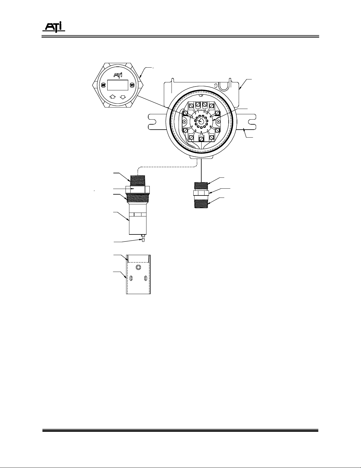
VIA THE RELAY PLUG MOUNTED ON THE BOTTOM
1 3/8
” FLATS
A12-17 TRANSMITTER MODULE
¾” NPT
1¼” NPT
EXPLOSION-PROOF ENCLOSURE
RELAY BASE
WALL MOUNT BRACKET
PLUG TRANSMITTER MODULE INTO THE RELAY BASE
OF THE TRANSMITTER MODULE.
¾” NPT
C10-17 COMBUSTIBLE SENSOR
¾” NPT
C28-17 COMBUSTIBLE SENSOR
WITH AUTO-TEST
1/8” TUBE I.D., BARB FITTING
1¼” NPT
SPLASH GUARD (00-0789)
Figure 1 - Transmitter Components
O & M Manual
Rev-H, 7/15 - 5 -
Page 6
A12-17 Combustible Gas Transmitter
A12-17 TRANSMITTER
Model A12-17 transmitters are available with a unique sensor verification system called Auto-Test.
This option consists of a miniature gas generator incorporated into the explosion-proof sensor assembly
which automatically generates a combustible gas every 24 hours. The gas generator function is
controlled by the microcontroller in the transmitter electronics. When activated, the generator will provide
a true gas test of the combustible gas sensing element, and will automatically alert operators to sensor
problems that might develop due to sensor poisoning or coating. Figure 1 shows both a standard sensor
and a sensor equipped with the Auto-Test generator.
The Auto-Test feature provides daily verification of sensor response. While it is not intended to
replace calibration, the automatic sensor test greatly reduces the amount of manual testing required to
assure that the gas detection system is functioning properly. Should a sensor fail to respond to the gas
test, the 4-20 mA signal from the transmitter is locked at 3 mA, providing a trouble signal to any receiving
equipment.
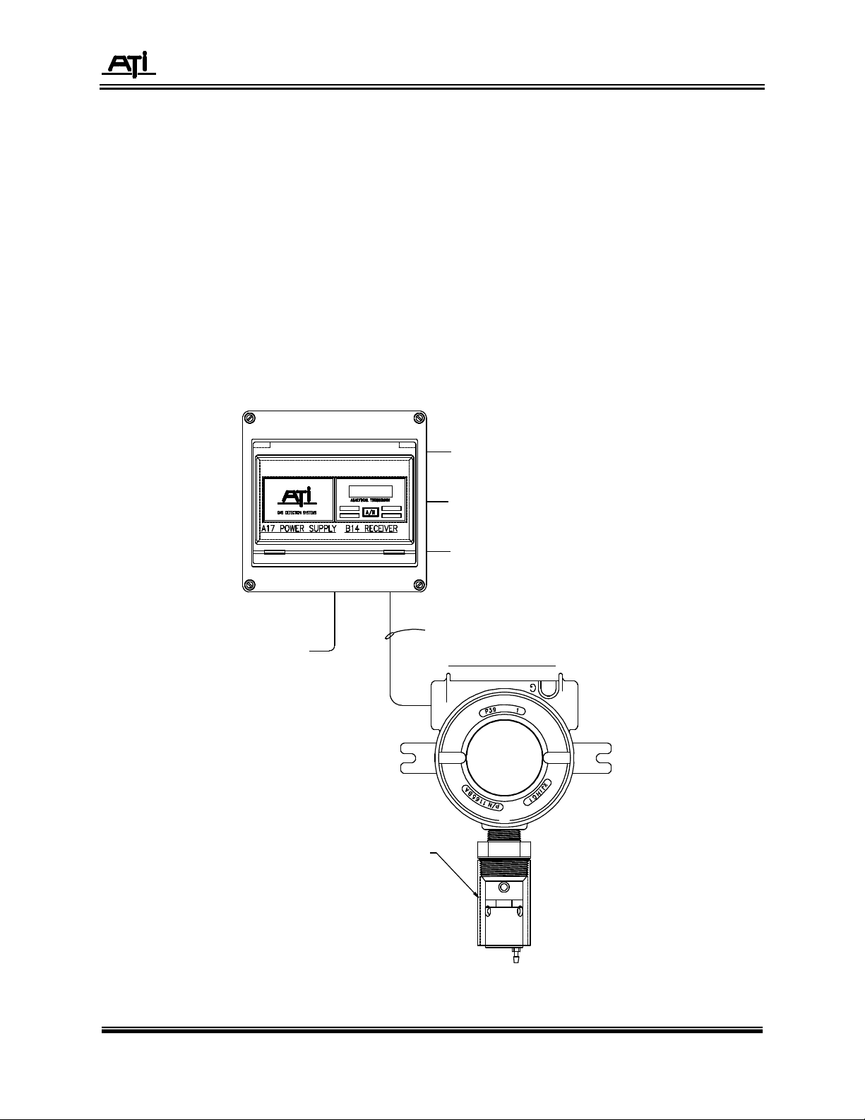
A typical installation for the A12-17 is shown in Figure 2 below. It is shown connected to ATI’s series
B14 single channel receiver, but the transmitter may be used directly with PLC, DCS, or computer
monitoring systems without the use of a special receiver.
4-20mA OUTPUT
POWER, 85-255 VAC or VDC
C28-17 GAS SENSOR WITH AUTO-TEST
(SHOWN WITH SPLASH GUARD)
(3) SPDT, 10A, ALARM RELAYS
(1) SPDT, 10A, TROUBLE RELAY
3 COND. 20 AWG UNSHIELDED OR SHIELDED CABLE
Figure 2 - Typical System Diagram
O & M Manual
Rev-H, 7/15 - 6 -
Page 7

A12-17 Combustible Gas Transmitter
SPECIFICATIONS
Range: 0-100% LEL (Lower Explosive Limit)
Display: 3 Digit LCD
Response Time (T90): 10 Seconds
Sensitivity: 1% LEL
Zero Drift: < 2%/Month
Power: 12-28 VDC, 12 VDC at 150mA nominal, 200mA max.
24 VDC at 75mA nominal, 100mA max.
Output: 4-20 mA DC, 375 ohms maximum load at 12 VDC
850 ohms maximum load at 24 VDC
1000 ohms maximum load at 28 VDC
Controls: Four magnetic control switches operable through glass window
Temperature Limits: -40° to + 70° C.
Sensor Type: Catalytic bead type, poison resistant
Sensor Option: Auto-Test gas generator
Sensor Materials: 316 Stainless Steel
Transmitter Enclosure: Cast Aluminum with Epoxy Coating, Glass window
Area Classification: NEC Class I, Groups B, C, & D, Class II, Groups E, F & G, Class III
Connections: 3 wire, 20 AWG, 500 feet max. (150 m.)
Sensor Cable Length: Maximum 50 feet for separation between sensor and transmitter
Weight: 4 lbs. (1.4 Kg.)
O & M Manual
Rev-H, 7/15 - 7 -
Page 8
A12-17 Combustible Gas Transmitter
INSTALLATION
Combustible gas sensor/transmitters are explosion-proof assemblies that are normally mounted
directly to suitable explosion-proof conduit. To maintain the explosion-proof integrity of the transmitter, a
suitable cable entry seal must be used in accordance with the applicable electrical code.
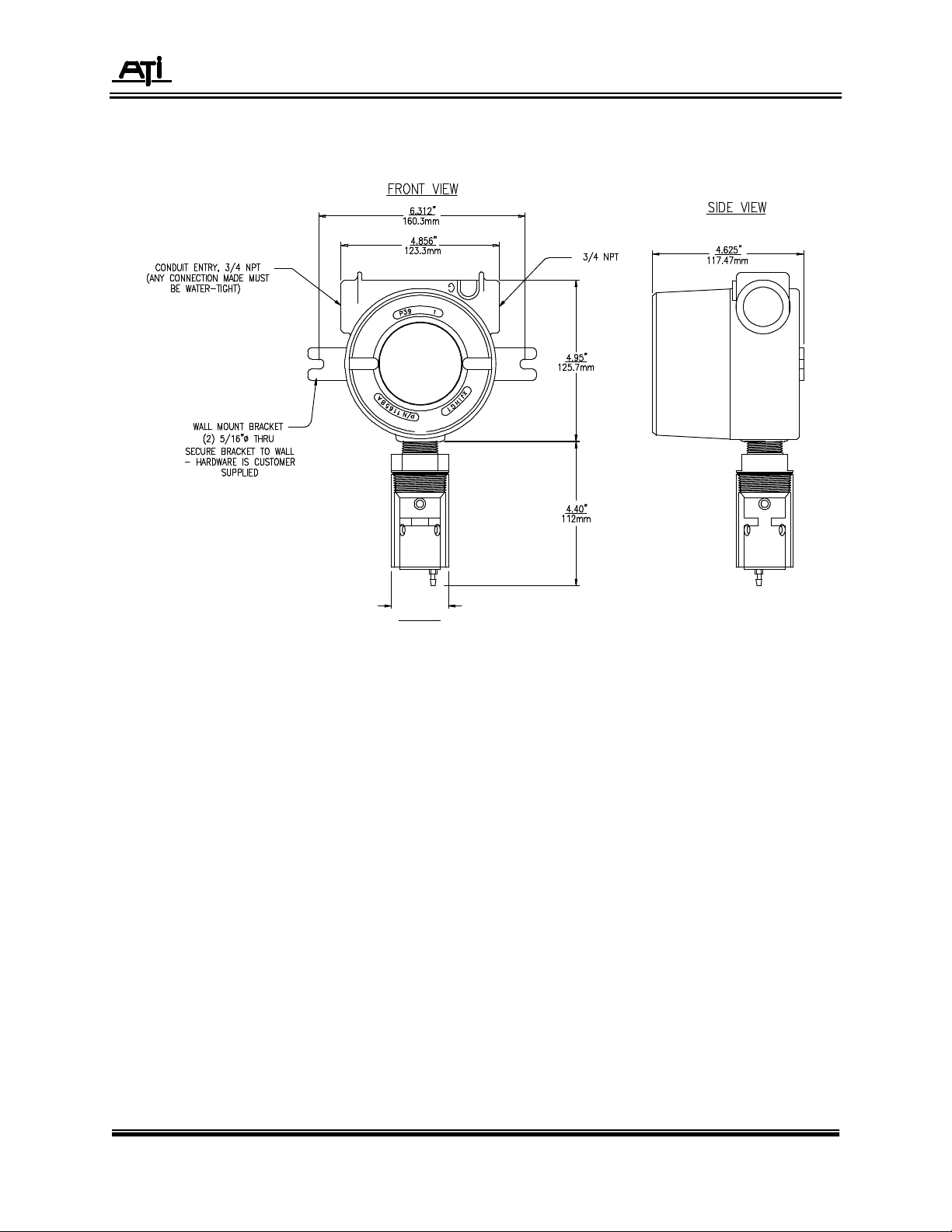
Sensor/transmitters should be mounted with the sensor facing down as shown in Figure 3 and 4. A12-17
transmitters are also supplied with a mounting bracket that can be used to secure the unit to a wall or
plate.
NOTE: Gas sensors without auto-test are shipped with a protective plastic cap over the end. This cap
should be left in place to avoid damage to the sensor during installation. If the detection system
is to be activated within a few days of installation, the cap should be removed when installation
is complete. Otherwise, leave the cap in place until the system is to be placed in service. Be
sure to leave the protective cap on the sensor if painting is to be done in the area of the
sensor.
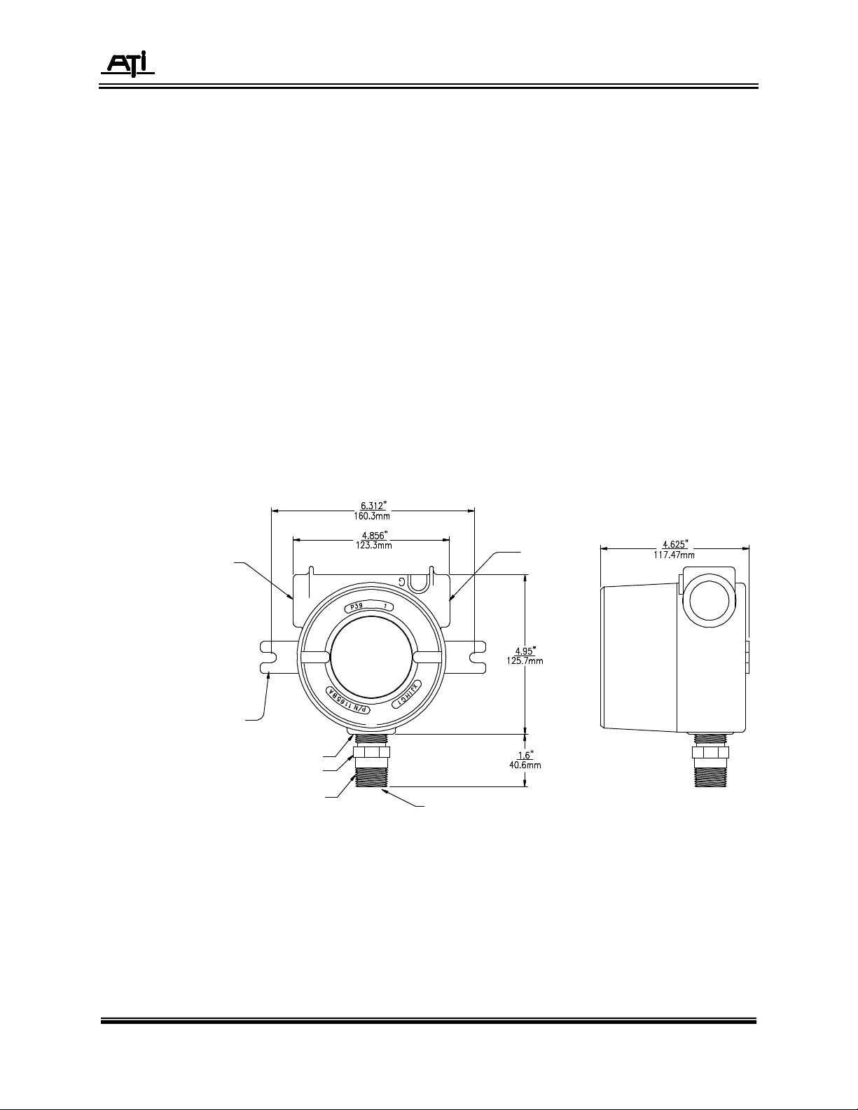
CONDUIT ENTRY, ¾” NPT
(ANY CONNECTION MADE MUST
BE WATER-TIGHT,
WALL MOUNT BRACKET
(2) 5/16” DIA. THRU
SECURE BRACKET TO WALL
- HARDWARE IS CUSTOMER
SUPPLIED
¾” NPT
1 1/8” HEX
¾” NPT
C10-17 COMBUSTIBLE SENSOR
Figure 3 - Gas Transmitter Dimensions, No Auto-Test
¾” NPT
O & M Manual
Rev-H, 7/15 - 8 -
Page 9
A12-17 Combustible Gas Transmitter
1.75” DIA.
Figure 4 - Gas Transmitter Dimensions, with Auto-Test
O & M Manual
Rev-H, 7/15 - 9 -
Page 10

A12-17 Combustible Gas Transmitter
SENSOR LOCATION
Combustible gas sensors are used to detect a variety of gases or vapors. The proper sensor
location will depend on the type of gas is expected. For gases that are lighter than air, such as methane,
sensors should be located near the ceiling. For gases that are heavier than air, such as butane, sensors
should be mounted near the floor. If the gas or vapor has a density near that of air, locate the sensor
about 5 feet off the floor in enclosed areas. Gas sensors mounted outdoors should be located near
anticipated leak sources (valves, flanges, compressors, etc.) and the location will depend on normal wind
patterns and anticipated employee activity areas.
The following are a few common combustible gases, along with their relative density (air = 1.00).
Densities less than one indicate gases that are lighter than air while those with densities greater than one
are heavier than air. Combustible vapors from most solvents, such an Benzene, n-Hexane, Methanol,
Ethanol, and MEK, are heavier than air and will tend to accumulate near the floor in enclosed spaces with
little air movement.
Methane 0.55
Butane 2.11
Propane 1.55
Hydrogen 0.07
Ammonia 0.60
INTERFERENCES
Combustible gas sensors contain two heated elements. One of these elements is active, and will
allow combustible gases or vapors to burn on its catalytic surface. The other is passive, and does not
react to gases. These two elements form two legs of a Wheatstone bridge measuring circuit. When
combustible gas contacts the sensor, the active element burns this gas and the temperature of this
element increases, changing its resistance. The transmitter measures the imbalance in the bridge circuit
and transmits the data to the receiver for display and alarming purposes.
Combustible sensors are adversely affected by a few compounds that may be present in a given
application. Probably the worst of these are silicone vapors from silicon based lubricants or sealants.
High silicon vapor concentrations can cause complete loss of sensitivity in as little as a few hours. These
sensors should not be used where silicon vapors are normally present, and sensors should be protected
from these vapors if such compounds are in use temporarily.
Lead compounds and high levels of hydrogen sulfide can also cause degradation of combustible
sensors. While lead vapors are not commonly encountered, they can also cause complete sensor failure
if encountered. Hydrogen sulfide will cause reduced sensitivity over the first few weeks of exposure, but
then will level out. The effect of hydrogen sulfide can normally be compensated for by re-calibration after
the first few weeks of use.
O & M Manual
Rev-H, 7/15 - 10 -
Page 11

A12-17 Combustible Gas Transmitter
GROUND TERMINAL
ELECTRICAL CONNECTIONS – TRANSMITTER
External connections to the A12-17 transmitter can be made using 3 conductor cable. Three
conductor cable uses one conductor (GND) as the power supply and output signal common. Figures 5
and 6 show power, output, and sensor connections for transmitters with and without Auto-test.
EARTH GROUND (OR CONDUIT)
3 CONDUCTOR CABLE
GROUND JUMPER (03-0067)
GND TERMINAL
LOCATED NEXT TO
RELAY BASE
TO COMBUSTIBLE SENSOR
POWER
POWER
RELAY BASE
C10-17 COMBUSTIBLE
SENSOR
Figure 5 - Transmitter Connections, no Auto-Test
O & M Manual
Rev-H, 7/15 - 11 -
Page 12

A12-17 Combustible Gas Transmitter
Figure 6 - Transmitter Connections with Auto-Test
O & M Manual
Rev-H, 7/15 - 12 -
Page 13

A12-17 Combustible Gas Transmitter
DUAL CONDULET SYSTEM
For some indoor applications, it is more convenient to mount the sensor toward the ceiling of the
room while keeping the transmitter electronics down at a convenient elevation for making calibration
adjustments. ATI’s dual Condulet system is designed for this purpose, and the interconnecting wiring is
shown below. A special remote calibration adapter can be used with this system to allow gas to be fed
from a point near the transmitter as shown in Figure 9
Figure 7 - Dual Condulet Connections, Sensor w/o Auto-Test
Figure 8 - Dual Condulet Connections, Sensor with Auto-Test
O & M Manual
Rev-H, 7/15 - 13 -
Page 14

A12-17 Combustible Gas Transmitter
Figure 9 - Dual Condulet Typical Installation
O & M Manual
Rev-H, 7/15 - 14 -
Page 15

A12-17 Combustible Gas Transmitter
A12-17 TO B14 CUSTOMER WIRING DIAGRAM
Figure 10 - B14 Receiver Connections
O & M Manual
Rev-H, 7/15 - 15 -
Page 16

A12-17 Combustible Gas Transmitter
A12-17 TO GENERIC INSTRUMENT WIRING DIAGRAM
Figure 11 - Generic Instrument Customer Wiring
O & M Manual
Rev-H, 7/15 - 16 -
Page 17

A12-17 Combustible Gas Transmitter
OPERATION
After mechanical and electrical installation is complete, the transmitter is ready for operation. Prior to
start-up, recheck the wiring connections to be sure power is connected to the proper terminals.
START-UP
When power is first applied, the transmitter will go through a start-up sequence. The LCD display will
indicate the following information.
tr X.X Indicates transmitter program version number
17 Two digit gas code number for combustible gas
100 %LEL Full scale range of the transmitter
InSt/nonE InSt - Indicates the sensor contains an Auto-Test generator.
nonE - Indicates the sensor does not contain an Auto-Test generator
Enab/disA *Enab - Indicates the automatic, 24Hr Auto-Test function is enabled.
disA - Indicates the automatic, 24Hr Auto-Test function is disabled.
XX.XH *Number of hours until the next automatic, 24Hr Auto-Test
XXXX *Number of successful sensor Auto-Tests.
XXXX *Number of unsuccessful sensor Auto-Tests.
All Segments Display test which powers up all display segments and flags
• Only displayed when the Auto-test generator is installed.
O & M Manual
Rev-H, 7/15 - 17 -
Page 18

A12-17 Combustible Gas Transmitter
START-UP DELAY
When the start-up sequence is complete, the display will begin to indicate gas concentration and will
display the mA lock flag, indicating that a start-up delay is in progress and that the mA output is locked at
4.0 mA. The delay period is 5 minutes, which provides time for the sensor to stabilize near zero before
the output is released. After 5 minutes, the lock flag will disappear and the output will begin to track the
gas concentration. The start-up delay can be canceled by activating the UP or DOWN arrow with the
magnetic screwdriver supplied with the unit.
FRONT PANEL MAGNETIC CONTROLS
The front of the transmitter module contains 4 magnetically activated controls. As shown in Figure 12,
these controls are MODE, ENTER, UP, and DOWN. A screwdriver with a suitable magnet is supplied
with each transmitter. This magnet allows for operation of the transmitter controls without removing the
cover of the outer enclosure. Magnetic controls are used for displaying information about the operation of
the transmitter, and performing zero and calibration functions. These controls also allow manual
activation of the Auto-Test function, and simulating manual adjustment of the 4-20 mA output to 4
different values for full system verification.
Figure 12 - Model A12-17 Front Panel
O & M Manual
Rev-H, 7/15 - 18 -
Page 19

A12-17 Combustible Gas Transmitter
E
D
CBF
G
H
I
K
L
LIQUID CRYSTAL DISPLAY
The display in the A12 transmitter provides the operator with a real time concentration display and a
variety of prompts for selecting transmitter operating modes. Figure 13 shows the display, including all of
the special indicators contained in it. Below the Figure is a description of each indicator.
Figure 13 - Liquid Crystal Display
A - Digital Concentration Display
B - Zero Indicator, activated while zeroing a sensor module or adjusting the 4 mA output value.
C - Span Indicator, activated while spanning a sensor module or adjusting the 20 mA output value.
D - Down Key Indicator, activated when the magnetic control marked “ò” is activated.
E - Up Key Indicator, activated when the magnetic control marked “ñ” is activated.
F - Auto-Test Indicator, activated when the transmitter is running the Auto-Test routine.
G - Fail Indicator, activated when an Auto-Test failure is detected.
H - mA Indicator, activated during output simulation mode or when the output is locked.
I - PPB Indicator (not used for combustible gas transmitters).
J - PPM Indicator (not used for combustible gas transmitters).
K - LEL Indicator, normally activated for combustible gas units.
L - % Indicator, normally activated for combustible gas units.
J
O & M Manual
Rev-H, 7/15 - 19 -
Page 20

A12-17 Combustible Gas Transmitter
MENU SEQUENCE
Operation of the transmitter is accomplished from the front panel using magnetic controls, with the
LCD providing visual indication of menu selections. Through menu selections, the user can review
information about the transmitter, calibrate the transmitter, manually activate the Auto-Test function (if
installed), simulate 4 different mA output values, and reset the transmitter to normal operation in the event
of an Auto-Test failure. Figure 14 provides a block diagram of the program in the A12-17 transmitter.
Figure 14 - Transmitter Program Chart
O & M Manual
Rev-H, 7/15 - 20 -
Page 21

A12-17 Combustible Gas Transmitter
Figure 14 cont’d - Transmitter Program Chart
O & M Manual
Rev-H, 7/15 - 21 -
Page 22

A12-17 Combustible Gas Transmitter
TRANSMITTER MODE SELECTION
The transmitter provides 4 main mode selections. After the display scrolls through the power-up
sequence and completes the start-up delay, it enters the NORMAL mode of operation, displaying gas
concentration. By holding a magnet over the MODE control, the display will indicate “InFo”. Repeating
this process will change the display to “tESt” and then “CAL”. The meaning of these modes is as follows:
InFo Designates INFORMATION mode. In this mode, you may review the information initially
displayed during the power-on sequence.
tESt Designates TEST mode. In this mode, the Auto-Test generator may be manually
activated, and the 4-20 mA output may be tested at 4 set values.
CAL Designates CALIBRATION mode. In this mode, the zero and span of the sensing
module may be adjusted, the 4 and 20 mA output current can be adjusted, and daily
Auto-Testing can be enabled or disabled.
INFORMATION MODE
To review the transmitter information, activate the MODE control until the display shows “InFo” and
then activate the ENTER control. The display will scroll through the same information shown during
power-up. See page 15 for details on the information displays.
TEST MODE
There are two selections available under the TEST menu. The first selection allows manual activation
of the Auto-Test by the operator. The Auto-Test option is only available when the Auto-Test generator is
installed. The second selection allows the transmitter output to be set to 4, 12, and 20 mA in order to
check the devices tied to the output. In addition, a failure condition can be simulated, causing the output
to go to about 3 mA.
MANUAL AUTO-TEST ACTIVATION
From the NORMAL display, activate the MODE control twice and the display will read “tESt”.
Activate the ENTER control. The display will change to “SEnS” and the AUTO TEST flag will be displayed
near the top of the display. If you activate the ENTER control at this point, the Auto-TEST sequence will
begin and the AUTO TEST flag will begin to flash. Activating the MODE control will allow you to escape
from this routine without activating the test sequence.
O & M Manual
Rev-H, 7/15 - 22 -
Page 23

A12-17 Combustible Gas Transmitter
When the test sequence is activated, the 4-20 mA output will be locked at the value being transmitted
before the sequence began, normally close to 4.0 mA. If you observe the LCD, you will see the gas
concentration begin to increase as gas is evolved from the generator. When the display reaches 5%
above the start value, a PASS message will flash on the display, indicating that the sensor passed the
test. At this point the AUTO TEST flag will stop flashing and go to steady on. This indicates that the
Auto-Test was successful but that the 4-20 mA output is still locked. The output will stay locked for the
next 2 minutes to allow the sensor to recover to zero. In addition, it will remain partially locked for an
additional 8 minutes to insure complete sensor recovery before again activating the output. However, if
the measured gas concentration goes above 50% of range during the second 8 minute inhibit period, the
output lock is released and any receivers connected to the transmitter will indicate high gas levels.
ANALOG OUTPUT SIMULATION
The A12-17 transmitter provides the ability to simulate 4 different current output values in order to test
the complete detection system. The output may be set to values of 4.0, 12.0, and 20.0, and may also be
set to the “Trouble” value of 3.0 mA.
From the NORMAL display, activate the MODE control twice and the display will read “tESt”.
Activate the ENTER control. The display will change to “SEnS” and the TEST flag will be displayed near
the top of the display. Activate the MODE control once and the display will change to tESt and the mA
flag will be on. Activate the ENTER control once and the display will indicate 4 mA. The current output
from the transmitter will now be locked on 4 mA. Use the UP or DOWN control to change the output to 12
mA, 20 mA, or “trbl” as desired. When “trbl” is displayed, the output will go to 3 mA, which is the output
value used to indicate “Trouble” with the transmitter. The output current from the transmitter will change
to the value shown on the display.
CAUTION: Simulation of 12 or 20 mA, or trb1 (3mA) outputs may cause receiving devices to
activate alarms and/or control devices. Never simulate these outputs without
inhibiting alarm receivers or notifying operating personnel that a system test is in
progress.
To escape the output simulation mode, activate the ENTER control once.
O & M Manual
Rev-H, 7/15 - 23 -
Page 24

A12-17 Combustible Gas Transmitter
CALIBRATION
A12-17 transmitters should be calibrated every 1-2 months. The frequency of calibration is dependent
on the operating environment and the degree to which accuracy is important. Sensors exposed to dirt, oil
mist, or vapors need more frequent calibration.
Transmitter calibration requires adjustment of both sensor zero and span. Sensor zero is adjusted
when the sensor is exposed to zero air. Adjusting the span requires a source of span gas with a known
concentration of combustible gas. Calibration kits, containing both zero air and span gas, are available
from ATI in various sizes. Contact ATI or your local ATI representative if you have any questions on
calibration gas sources.
NOTE: The output of the A12 transmitter is locked at 4 mA when in the calibration mode. This
means that the 4-20 mA output will not change when span gas is applied. Only the LCD
display will indicate changing gas concentrations. To verify output operation using span
gas, apply gas while the transmitter is in the NORMAL mode of operation after calibration
is complete.
ZERO ADJUSTMENT
As previously mentioned, adjusting the transmitter zero requires that the sensor be exposed to air that
is free of combustible gas. If the area in which the sensor is operating is known to be gas free, then the
transmitter can be zeroed without further equipment. If not, use of “zero air” from a gas cylinder is
recommended. Zero air is available as part of all ATI calibration kits, or may be obtained from any
specialty gas supplier. When zero air is to be used, a calibration adapter must be used. The calibration
adapter provides a confined space around the sensor into which the zero air can flow. Calibration
adapter provide tubing fittings at the bottom to connect air tubing as shown in Figure 15. If your sensor is
furnished with the Auto-Test generator, a calibration gas fitting is supplied at the bottom of the sensor
assembly and is left in place at all times. For these systems, no separate calibration adapter is needed.
Figure 15 - Calibration Adapter Assembly
O & M Manual
Rev-H, 7/15 - 24 -
Page 25

A12-17 Combustible Gas Transmitter
To zero the transmitter, allow zero air to flow to the sensor for 5 minutes. If the sensor is located in air
known to be gas free, the 5 minute delay is not necessary. Set the new zero value as follows:
Step 1 With the LCD indicating normal mode of operation, activate the MODE control repeatedly until the
display shows “CAL”. Activate the ENTER control. The display will change to “SEL” and the “Z”
(for Zero) flag on the display will light.
Step 2 Activate ENTER again and the display will indicate the gas concentration. The value should be
close to zero. Observe the display to be sure it is not either increasing or decreasing.
Step 3 When the display value is stable, activate ENTER again and any small sensor offset will be
stored in memory. The display will briefly show “StOr”, then change to “SEL” and the “S” (Span)
flag will light. If you wish to span the transmitter, proceed to step 2 of the next section of this
manual. If you only wish to set the zero, activate MODE until the display indicates “donE”.
Activate ENTER to return to the normal operating mode.
SPAN ADJUSTMENT
Adjusting span requires a source of reliable span gas. ATI calibration kits contain a 1% methane
standard equivalent to 20% LEL. Other concentrations or other gas types may be used if preferred.
To adjust the sensing module span, proceed as follows:
Step 1 Advance through the transmitter program using the MODE and ENTER controls until the display
indicates “SEL” and the “S” and “% LEL” flags are lit. This display is indicating that you can now
select the span mode.
Step 2 Activate ENTER and the display will indicate gas concentration. The “S” flag will remain lit and
the “mA “ flag will light indicating the transmitter output is locked at 4mA.
Step 3 Screw a calibration adapter onto the sensor as shown in Figure 15. Connect your span gas
source to either the inlet fitting on the calibration adapter or to the tube fitting supplied as part of
the Auto-Test sensor assembly.
Step 4 Turn on the calibration gas and allow it to flow for 3 minutes. The LCD should increase in
response to the sensor being exposed to the target gas. After 3 minutes, use either the UP or
DOWN controls to adjust the value on the display to 20% LEL (or appropriate value if another gas
standard is in use).
Step 5 Activate ENTER and the new span constant will be stored. The display will briefly show “StOr”,
then indicate “donE”. Activate ENTER to return to normal operation.
O & M Manual
Rev-H, 7/15 - 25 -
Page 26

A12-17 Combustible Gas Transmitter
mA OUTPUT ADJUSTMENT
Series A12 transmitters provide a method of adjusting (or offsetting) the 4 and 20 mA output values
slightly in order to insure that other devices in the output loop read the correct value. In effect, these
adjustments are the equivalent of fine zero and fine span controls.
Adjustment of the 4 and 20 mA values is done through the CAL mode. From the NORMAL display,
activate MODE until the display reads “CAL”. Activate ENTER once and then MODE twice so that the
display reads “SEL” with the Z and mA indicators on. Activate ENTER and the display will change to
“SET”, with the Z and mA indicators still on. Use the UP or DOWN controls to move the 4 mA value up or
down as required. The display will not indicate the output value. This must be read using a mA meter or
by observing another display tied to the transmitter output.
When adjustment is complete, activate the ENTER control and the display will change to “SEL” with
the S and mA indicators on. Activate ENTER and repeat the above process to adjust the 20 mA value as
required. When adjustment is finished, activate ENTER to store the value and ENTER again when the
display indicates “donE”. This will take you back to the NORMAL display and mode of operation.
AUTO-TEST ENABLE/DISABLE SELECTION (Units with Auto-Test)
The automatic daily Auto-Test function on the A12-17 transmitter can be activated (enabled) or
deactivated (disabled) from the calibration menu. Normally, this function will be enabled at all times so
that the sensor response is verified regularly. However, should a problem arise with the generator, the
Auto-Test function can be disabled while a new module or generator is obtained. If the sensor is still
functional, disabling the Auto-Test allows the transmitter to continue normal operation without attempting
its normal 24 hour test sequence.
If the transmitter was shipped with a sensor containing an Auto-Test generator, the Auto-Test function
will be enabled at the factory. To disable this function, start from the NORMAL display and activate the
MODE control three times to display “CAL”. Activate ENTER once and then the MODE control 4 times.
The display should now indicate “EnAb”. Use the UP or DOWN control to toggle to “dISA”. Activate the
ENTER control to store the disable value. When the display indicates “donE”, use ENTER to return to the
NORMAL display.
O & M Manual
Rev-H, 7/15 - 26 -
Page 27

A12-17 Combustible Gas Transmitter
GAS
% LEL
CALIBRATION FOR OTHER COMBUSTIBLE GASES
As previously mentioned, a combustible gas sensor has a slightly different response to each
combustible gas or vapor. In addition, the LEL (Lower Explosive Limit) represents different percent
concentrations for different gases. For instance, the LEL for methane is 5% by volume while the LEL for
butane is 1.9% by volume. Because of these factors, a combustible transmitter must be adjusted
differently if the system is intended to detect a gas or vapor other than methane.
A 1% methane gas standard may still be used for calibration of combustible transmitters when used
for other gases. However, the %LEL value set on the LCD will be different for each gas. Table 1
provides the LEL setting for various gases. The setting assumes the use of 1% methane as the span
gas. As an example, to calibrate the transmitter for hexane detection using 1% methane standards, apply
the 1% Methane gas in accordance with the span adjustment instructions but set the LCD to 50% in step
4.
TABLE 1
Methane 20
Propane 35
n-Butane 35
n-Pentane 40
n-Hexane 50
Hydrogen 30
Methanol 30
Ethanol 40
Isopropyl Alcohol 55
Acetone 50
Methyl Ethyl Ketone 50
Benzene 55
Toluene 60
Di-ethyl Ether 10
Ammonia 15
Methyl T-Butyl Ether 46
SENSOR RESPONSE TEST
While zero and span adjustments are required only periodically, gas sensors should be checked
regularly for proper response. The response check can be done quickly by simply aiming the outlet tube
from the span gas cylinder at the face of the sensor and turning on the gas flow for 10-20 seconds. The
sensor should begin to respond within 5 seconds. If the sensor does not respond, it should be replaced.
This type of manual testing is normally not required for systems supplied with the Auto-Test generator.
However, it should be used to test the sensor in the event of an Auto-Test failure.
CAUTION: This response test will cause the output to increase and may cause receiving devices
to activate alarms and/or control devices. Never run a sensor response test without
inhibiting alarm receivers or notifying operating personnel that a system test is in
progress.
O & M Manual
Rev-H, 7/15 - 27 -
Page 28

A12-17 Combustible Gas Transmitter
ERROR MESSAGES
The A12-17 constantly evaluates the condition of the sensor and the output loop to detect errors that
might compromise the performance of the instrument. The following messages will appear on the LCD
display if the transmitter detects certain failures.
AUTO TEST FAIL
: This message is displayed if the transmitter is equipped with the Auto-Test option and the
sensor fails to respond to 3 successive tests at one hour increments. Unusual
environmental conditions can cause an occasional test failure, so the system will retest the
sensor an hour later if a failure occurs. After 3 failures, the AUTO TEST FAIL message
appears and the output goes to 3 mA. If this occurs, test the sensor with calibration gas to
determine if the failure is due to the sensor or the gas generator. Sensor or generator
replacement will most likely be needed. Should the Auto-Test failure message appear due
to a generator failure, the transmitter will still perform its function. Activating the ENTER
key will clear the alarm. Should the sensor detect a combustible level above 50% LEL,
the failure condition will be over-ridden and the output will immediately reflect the
measured gas value.
SEnS
LOOP
U.r.
O.r.
FAIL
: This message is displayed when the transmitter has detected an open or short in either
the active or passive sensor elements. When this error occurs, the output loop goes to 3
mA and will stay at that value until the problem is corrected. Activating the ENTER key
will clear the alarm, if and only if the problem has been corrected. Otherwise the
display will still display sens fail. Should the detector measure a gas value greater than
50% LEL, the unit will override the error condition and begin to transmit the measured gas
value.
FAIL
FAIL
FAIL
: This message is displayed in alternation with the normal LEL display if the transmitter
detects an open circuit or short in the 4-20 mA output loop. The transmitter will continue
to function normally and will accurately display combustible gas levels. However, any
instrument tied to the output will not respond to changes at the transmitter. This condition
should be corrected immediately as no alarms are likely to be activated during loop
failure.
: This message is displayed when the transmitter has detected a negative zero drift greater
than 15% of full scale. The transmitter output is locked at 3 mA. The display will
alternate between the current gas concentration and “U.r.”. The unit should be checked
for proper operation. Sensor zero should be set and system response should be
checked. Activating the ENTER key will clear the alarm.
: This message is displayed when the transmitter has detected a gas concentration greater
than 110% full scale. The transmitter output will track the gas concentration and does not
lock at any value. The display will alternate between “O.r.” and the current gas
concentration. Once the gas concentration falls below 110% full scale, the alarm can be
cleared by activating the ENTER key.
O & M Manual
Rev-H, 7/15 - 28 -
Page 29

A12-17 Combustible Gas Transmitter
SENSOR REPLACEMENT
Combustible gas sensors used in the A12-17 are warranted for 12 months and generally last 2 years
or more in the absence of poisoning agents. When sensor replacement is required, it can be done easily
and quickly. Power down transmitter in accordance with all applicable safety standards and procedures.
Open the transmitter enclosure and unplug the transmitter electronics module. Disconnect the 3 or 5
sensor wires from the octal base and unscrew the sensor from the explosion-proof transmitter housing.
Screw in the replacement sensor and reconnect at the octal base. After a new sensor has been
connected, allow 4 hours for the new sensor to completely stabilize. Then perform a zero and span
calibration as described on pages 21 through 22.
Sensor assemblies equipped with Auto-Test gas generators can have new generators installed at the
factory. If the generator should fail and the sensor still show good response, contact ATI and arrange for
generator replacement. The sensor in this type of assembly cannot be replaced separately.
O & M Manual
Rev-H, 7/15 - 29 -
Page 30

A12-17 Combustible Gas Transmitter
Part Number
Description
SPARE PARTS LIST
03-0120 A12-17 Combustible Transmitter Module
03-0121 Explosion-proof Enclosure with Base
00-0252 C10-17 Combustible Gas Sensor
00-0258
00-0261
00-0298
00-0786 C28-17 Combustible Gas Sensor with Auto-Test
00-0789
00-0263 C10-17 Junction Box w/ Sensor
00-0787
03-0182 C28-17 Junction Box Assembly (No Sensor)
03-0183 C10-17 Junction Box Assembly (No Sensor)
Calibration Adapter (sensor without auto-test)
Remote Calibration Adapter/Rain Shield (sensor without auto-test)
Flowcell (sensor without auto-test)
Splash Guard (for sensor with auto-test)
C28-17 Junction Box w/ Sensor (Auto-Test Version)
O & M Manual
Rev-H, 7/15 - 30 -
Page 31

PRODUCT WARRANTY
Analytical Technology, Inc. (Manufacturer) warrants to the Customer that if any
part(s) of the Manufacturer's products proves to be defective in materials or
workmanship within the earlier of 18 months of the date of shipment or 12 months of the
date of start-up, such defective parts will be repaired or replaced free of charge.
Inspection and repairs to products thought to be defective within the warranty period will
be completed at the Manufacturer's facilities in Collegeville, PA. Products on which
warranty repairs are required shall be shipped freight prepaid to the Manufacturer. The
product(s) will be returned freight prepaid and allowed if it is determined by the
manufacturer that the part(s) failed due to defective materials or workmanship.
This warranty does not cover consumable items, batteries, or wear items subject to
periodic replacement including lamps and fuses.
Gas sensors, except oxygen sensors, are covered by this warranty, but are subject to
inspection for evidence of extended exposure to excessive gas concentrations. Should
inspection indicate that sensors have been expended rather than failed prematurely, the
warranty shall not apply.
The Manufacturer assumes no liability for consequential damages of any kind, and
the buyer by acceptance of this equipment will assume all liability for the consequences
of its use or misuse by the Customer, his employees, or others. A defect within the
meaning of this warranty is any part of any piece of a Manufacturer's product which
shall, when such part is capable of being renewed, repaired, or replaced, operate to
condemn such piece of equipment.
This warranty is in lieu of all other warranties (including without limiting the generality
of the foregoing warranties of merchantability and fitness for a particular purpose),
guarantees, obligations or liabilities expressed or implied by the Manufacturer or its
representatives and by statute or rule of law.
This warranty is void if the Manufacturer's product(s) has been subject to misuse or
abuse, or has not been operated or stored in accordance with instructions or if the serial
number has been removed.
Analytical Technology, Inc. makes no other warranty expressed or implied except as
stated above.
Page 32

WATER QUALITY MONITORS
Dissolved Oxygen
Free Chlorine
Combined Chlorine
Total Chlorine
Residual Chlorine Dioxide
Potassium Permanganate
Dissolved Ozone
pH/ORP
Conductivity
Hydrogen Peroxide
Peracetic Acid
Dissolved Sulfide
Residual Sulfite
Fluoride
Dissolved Ammonia
Turbidity
Suspended Solids
Sludge Blanket Level
MetriNet Distribution Monitor
GAS DETECTION PRODUCTS
NH3 Ammonia
CO Carbon Monoxide
H2 Hydrogen
NO Nitric Oxide
O2 Oxygen
CO Cl2 Phosgene
Br2 Bromine
Cl2 Chlorine
ClO2 Chlorine Dioxide
F2 Fluorine
I2 Iodine
HX Acid Gases
C2H4O Ethylene Oxide
C2H6O Alcohol
O3 Ozone
CH4 Methane (Combustible
Gas)
H2O2 Hydrogen Peroxide
HCl Hydrogen Chloride
HCN Hydrogen Cyanide
HF Hydrogen Fluoride
H2S Hydrogen Sulfide
NO2 Nitrogen Dioxide
NOx Oxides of Nitrogen
SO2 Sulfur Dioxide
H2Se Hydrogen Selenide
B2H6 Diborane
GeH4 Germane
AsH3 Arsine
PH3 Phosphine
SiH4 Silane
HCHO Formaldehyde
C2H4O
DMA Dimethylamine
Peracetic Acid
3
 Loading...