

ATI Technologies 39-0050 Installation & Operation Manual
DIGITAL CONTROL
INSTALLATION
& OPERATION
Version - April 2006
For Software Versions V2.05 & V2.06
Part Number - 39-0050
© ATL Agricultural Technology Limited: April 2006

GOOD PRACTICE: Mains Supply.
Power Supply: Siting.
ATL Power Supply: Output Voltages.
ATL power supply outputs are factory set and should not be adjusted. For a 230volt mains supply the DC outputs
should be:
Feeder Supply with 4 feeders running: 13.6volts.
The feeder supply is fused at either 20 or 30Amps depending upon the type. Additionally, there is a thermal cutout
associated with the feeder supply which will remove power from the feeders in the event of an overload. It may take several
minutes for the supply to be restored if the cutout does operate.
There are two indicators fitted to the base of the power supply casing; red indicates that the mains is present and
green that the regulated feeder supply is available.
Control and Feeder Cables and Conduit.
Cables must be kept as short as possible running directly from point to point. Cut out any excess cable rather than
leaving it coiled.
Wherever possible cables should be contained in a waterproof conduit using
o
Keep multicore cables away from other cables especially those carrying mains or heavy currents. Cross only at 90
where necessary and do not enclose in conduit with other cables.
A separate mains supply and earth running directly from the consumer meter is essential.
Avoid routing the mains cable to the power supply close to other supplies especially those providing intermittent
current- motors that are starting and stopping continually or high power heaters with thermostatic control.
Terminate in a sealed, fused, double pole switched outlet fitted with a 13Amp (Type 1362) fuse or trip. A 3-pin ring
main socket is not suitable in parlour conditions. All mains cabling must be contained in a firmly secured durable conduit.
Fix the power supply to a wall or suitable brackets in a well ventilated area sufficiently high to avoid physical contact
or damage, leaving a gap of at least 250mm (10") between the top of the power supply casing and the ceiling.
Position the power supply so that the output (low DC voltage) cables are as short as possible even if this means
extending the mains supply.
the correct csa cable specified in the
diagrams.
Entries must be made into the bottom of power supply or control casings but never into the top. This will invalidate the
warranty.
Strip existing cables back to bright copper before connection.
DIGITAL CONTROL
INSTALLATION
& OPERATION: INDEX
INDEX
Good Practice: Index
Operating the Control: 1
Installation: 2
Vacuum Operated Feeders: 2
Electric Feeders: 3
Feeder Calibration Slides: 3
Special Feeder Connections: 3
The Global Timing Pulse: 3
Single Feeder Connections: 4
Double Feeder Connections: 4
12volt Single Feeder: Herringbone Parlour Connections 5
12volt Double Feeder: Herringbone Parlour Connections 6
12volt Double Feeder: Abreast Parlour Connections: 7
12volt Feeder Connections using existing 12volt
Power Supply and ATL Control Power Supply: 8
12volt Feeder Connections using ATL Digital Power
Supply with Global Timing Pulse: 9
Feeder Connections using ATL Control Only Power
Supply with Global Timing Pulse: 10
Fault Finding: 11
Data Sheets Included:
Datasheet 08A - Mechanical-Electronic Conversion
Datasheet 08B - Feeder Interface
Datasheet 08C - 24volt AC Interface
Datasheet 08D - Control Only PSU - Westfailia Feeders
Datasheet 23A - Wesfalia Resistor Fitted
Datasheet 23B - Westfalia Resister NOT Fitted
n
n
n
n
n
n
n
n
n
n
n
n
n
© ATL Agricultural Technology Limited: April 2006
However, the opposite side feeder can be set to run by pressing the Feed Switch but it will not
deliver the ration displayed since it is working in stand-by mode, running just so long as the
Feed Switch is held over.
Setting the Ration Display to zero and pressing the Feed Switch will deliver cake continuously
for as long as the switch is held over. This is a convenient stand-by feature.
Software Versions
The Digital Feeder Control is supplied with one of two versions of software:
V2.05 - Standard Version - Once the feed switch is operated and the counter has counted down
to zero (0), the ration display stays at zero (0) and a new ration has to be dialled up to feed
again.
V2.06 - Return To Ration Version (Rotary Parlour) - Once the feed switch is operated and the
counter has counted down to zero (0), the ration display returns to the previous ration value
ready to feed again. NB - The ration can be altered by turning the ration selector knob.
DIGITAL CONTROL
INSTALLATION
& OPERATION: 1
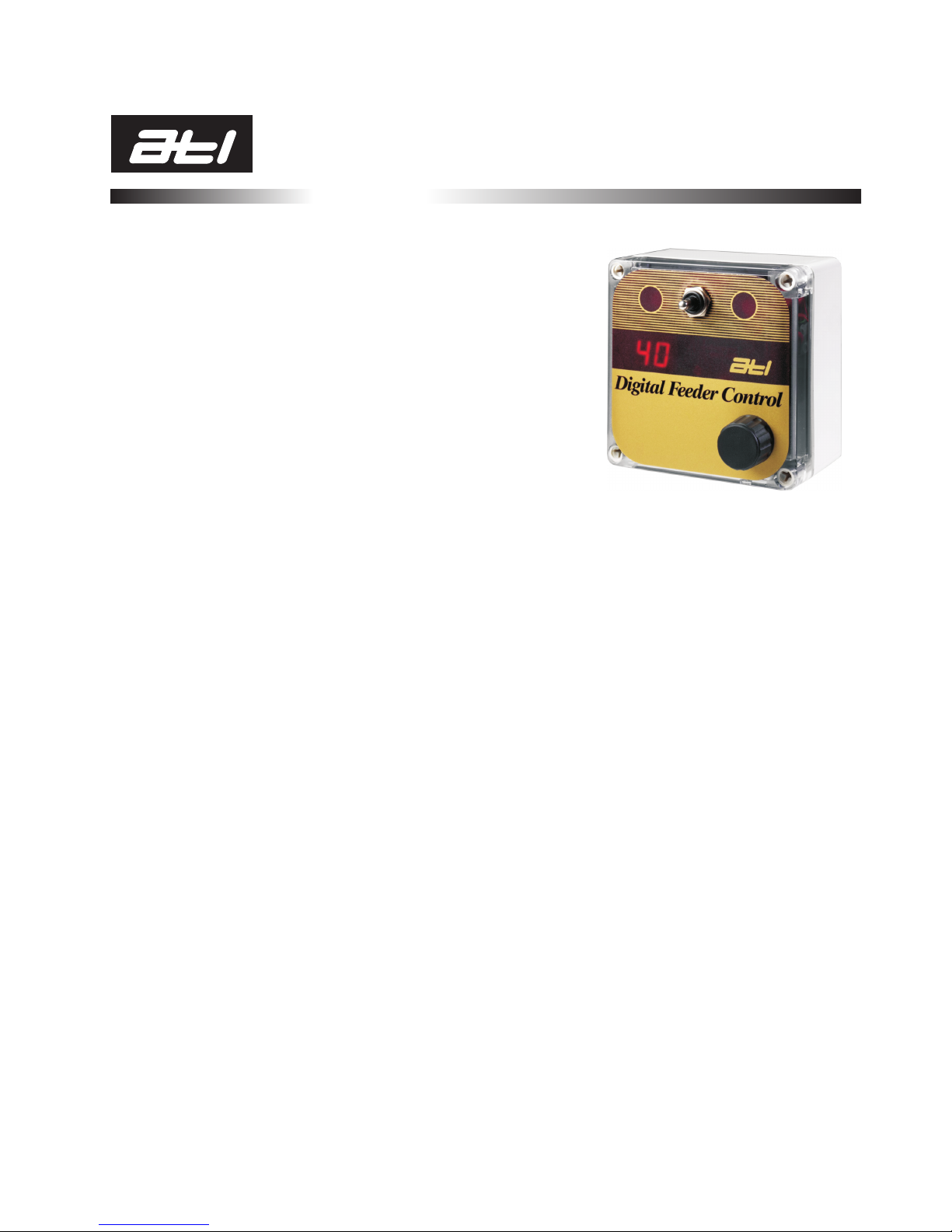
The Digital Feeder Control from ATL Agricultural Technology offers a most elegant and yet
simple way of feeding in parlour.
It is connected to either a single feeder, an ATL Abreast Feeder with automatic feed flaps or two
feeders one on each side of the parlour. Setting up the installation to deliver a consistent portion
of feed from any feeder is quick and easy by virtue of the Global Timing Pulse, a unique
innovation in parlour feeding.
Feeding is fast- really fast. Just dial the number of portions required for a cow, press the FEED
switch and it's done. The feeder will deliver the cake completely unattended. No fiddly buttons
to press or complex codes to remember. The ATL Digital Feeder Control gives the farmer
complete control.
Operating the Control
The feeding procedure for the Digital Feeder Control is simple. Turning the Ration Selector knob
increases or decreases the ration which is displayed in the window. For controls set up to drive a
single feeder such as the ATL Abreast unit with a manual flap, pressing the Feed Switch in either
direction will start the feeder, both Indicators illuminate and the display counts down as the
feed is dispensed until it reaches zero and the feeder motor turns off.
Controls which drive two feeders, pressing the feed switch to the left starts the feeder on the left
and pressing it to the right starts the feeder on the right. The appropriate Motor Running
Indicator illuminates to show which ‘side’ is running and again, when the display reaches zero
the feeder is turned off.
ATL Abreast Feeders with an Automatic flap have a single feeder motor which operates
regardless of whether the Feed Switch is pressed left or right, but the Auto flap is moved in the
direction of the Feed Switch to divert the cake to that manger. Press and hold the Feed Switch for
a few seconds to allow the Auto flap to move and settle.
The Ration Selector is a rotary switch; it has no end stops and can be rotated through 360
degrees in either direction. As it is turned, the display increments or decrements, depending
upon direction. The display number represents the multiple of portions (to a maximum of 99)
set up using the Timing Pulse. So, for example if the installation was calibrated to deliver
500gms (about 1pound), a figure of '7' in the display window represents 7 x 500gms or
3.5kilograms.
If the Motor Running Indicator(s) fail to illuminate when the Feed Switch is pressed and the
Ration Display begins to flash, there is a fault with the feeder and the thermal trip inside the
Control has interrupted the feeder power supply. This generally means the feeder motor is
drawing too much current- it may be jammed, badly worn or has short-circuit windings.
Release the switch, turn the Ration Selector until the display reads 'zero, allow the thermal trip
to cool for a minute or so and try again. If the fault persists check and service the feeder motor.
Even when the feeder is running it is possible to increase or decrease the ration simply by
turning the Ration Selector. The Digital Feeder Control will deliver the new ration.
If a feeder is already running, pressing the Feed Switch again for that side will have no effect.
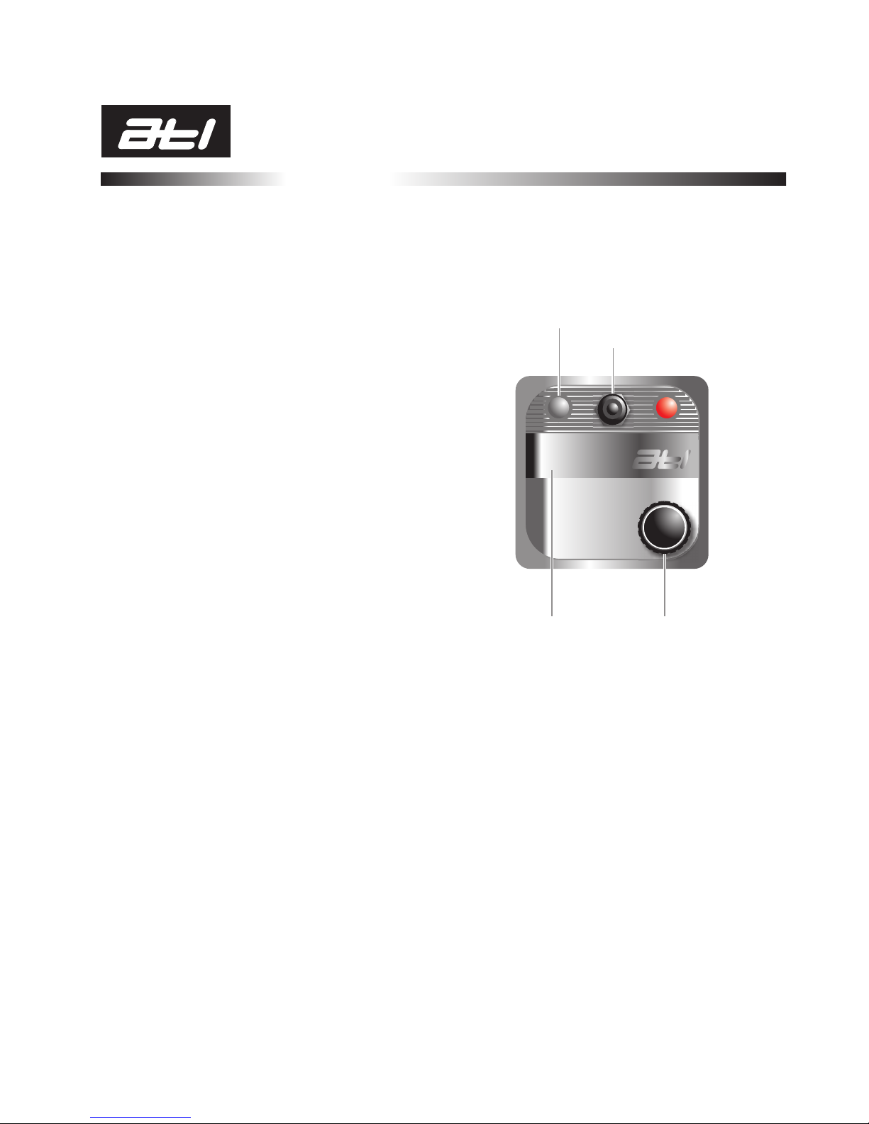
Ration Display Ration Selector
Motor Running Indicator LEDs: Left and Right
Feed Switch
Digital Feeder Control
88
© ATL Agricultural Technology Limited: April 2006
DIGITAL CONTROL
INSTALLATION
& OPERATION: 2
Installation
Power Supplies or Interfaces must be provided with a clean 230volt mains supply. Avoid
sharing an outlet with another load. Use a switched, fused outlet not a 13Amp plug and socket.
Position the Digital Feeder Controls as high as possible away from moisture and splashes
but within easy, convenient reach. Cable runs should be as short as possible.
The DC supply to the Controls and the Timing Pulse cable may occupy the same conduit,
but must be kept separate from the Feeder DC, Milk Pump and Vacuum Pulsation Unit supplies.
Cables should be at least 500mm from mains cabling and as far away from fluorescent lights as
possible; they can interfere with the Timing Pulse.
Always use the cable entries along the bottom edge of the Control casing. Although some
of the diagrams show entry to the side or top of the case, this is for clarity only and must be
avoided.
Do not position the Controls along a straight run of conduit- use 'T' connectors. Straight
runs create unimpeded air paths and moisture can be deposited inside the Controls.
Err on the generous side for cable sizes. Minimum recommendations are:
2.5mm csa for DC power supplies to Digital Feeder Control.
1.5mm csa for Digital Control to Feeder Motors.
0.5mm csa for Timing Pulse supply from power supply to Control.
A single run of 2.5mm csa cable from the power supply will provide sufficient power for up to 6
Controls. Additional Controls will require a further cable run back to the power supply. Two
outlets are provided for both (+) and (-) cables on ATL power supplies. Arrange the cable
neatly inside the Control casing. Never loop or coil spare cable- cut it to the correct length.
If new Controls are replacing the older mechanical type, check the existing connections
cutting away any 'blackened' cable before fitting the cables. The connector configurations are
different between old mechanical and new digital types (Data Sheet 8A).
Diodes must be fitted across low voltage (12 or 24volt) DC feeder motors or solenoid
terminals. ATL feeders already have these fitted as standard; most other makes do not.
Running a motor without a diode fitted will expose the Control circuitry to back emf, could cause
irreparable damage and will certainly void the warranty. Do not fit diodes to high voltage - 110
or 230volt motors or any motor operating with an AC supply.
Check for splits or holes to switch covers and the display membrane. If there is any
opportunity for water to enter the casing do not use the Control. Doing so could jeopardise the
warranty. Replace the damaged part as soon as possible.
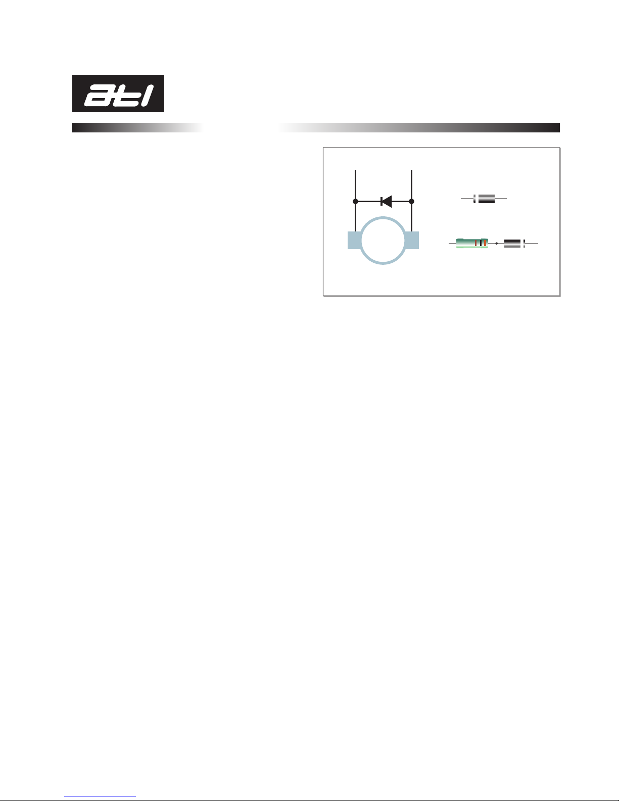
Diode connection across motor terminals.
M
+ -
The positive end of the diode is marked
with a band; connect to the (+) terminal.
Preferred arrangement with a resistor in
series with the diode
Resistor: 100 Ohms (100R) 2watt
Diode: 1N4002 100v PIV 1Amp or better
Do NOT fit diodes to AC motors.
The Control can operate both electric and vacuum feeders; 12 volt DC electric motor feeders are
supplied directly from the control whereas vacuum feeders are operated via a solenoid valve.
Higher voltage feeders can be accommodated but require a Feeder Interface to switch the high
voltage- AC or DC- to the feeder motors.
Before the system is switched on for the first time, the output configuration must be
checked. The Configuration Jumper is located on the rear of the Control circuit board, bottom
right-hand corner (see page 3).
Vacuum Operated Feeders:
Vacuum feeders will need the Jumper to be fitted in one of the three positions shown in Figures
(2 to 4) on the following page. The actual position- 1, 2 or 4 pulse depends upon the feeder
type. As a general guide, the major makes should be set as follows:
Manufacturer Pulse(s) Feed/Pulse(grms)
Fullwood Rationmaster 1 or 2 500
Alfa Laval 2 or 4 500
Orby 1 500
Somerset 4 100
Westfalia EP 1 700
Westfalia M Type 1 or 2 100
The Global Timing Pulse (see page3) provides a facility for varying the pulse duration and
therefore, the speed of repeated pulses.
© ATL Agricultural Technology Limited: April 2006
DIGITAL CONTROL
INSTALLATION
& OPERATION: 3
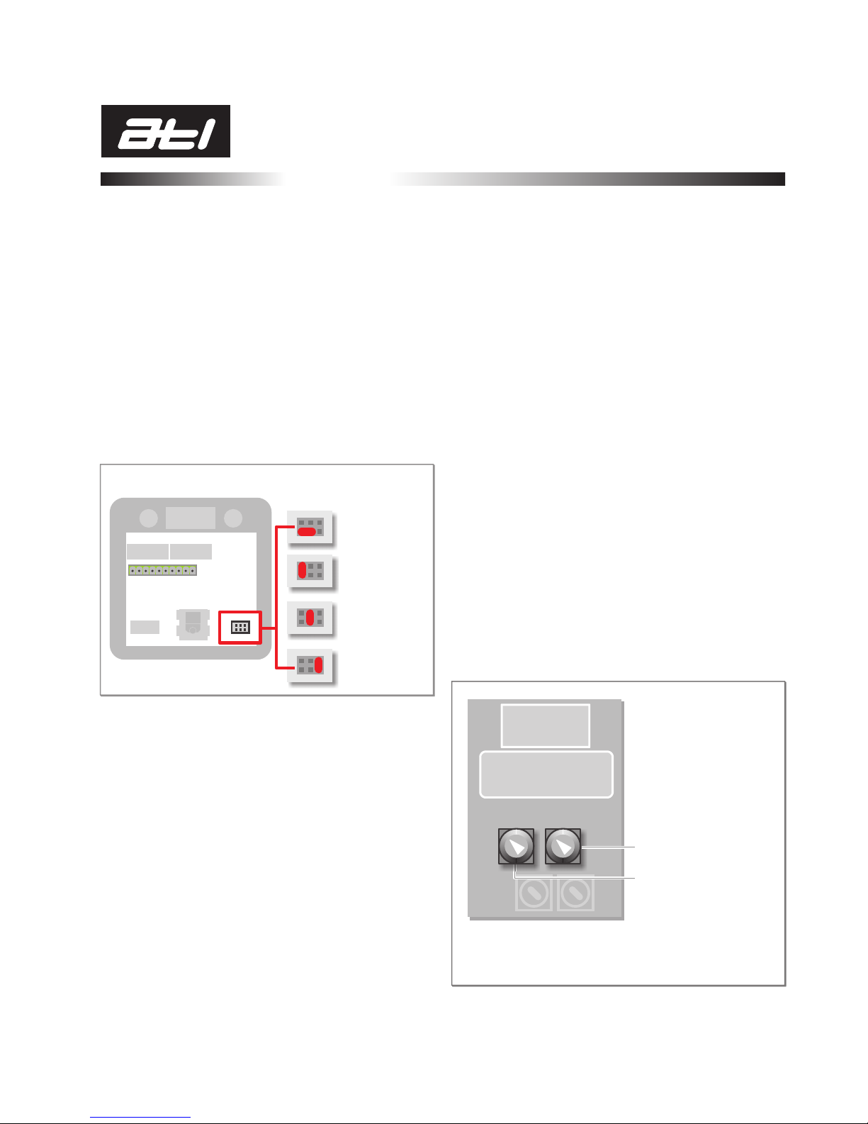
Figure (1): Jumper position
for electric feeders
Figure (2): Jumper for
vacuum feeders: 1 pulse
Figure (3): Jumper for
vacuum feeders: 2 pulse
Figure (4): Jumper for
vacuum feeders: 4 pulse
Electric Feeders.
For electric feeders the jumper must be positioned as shown in Figure (1). A broad indication of
running time per 500grms of feed delivered for motorised feeders is:
Manufacturer Voltage Running (Secs)
ATL 12 2.2
Gascoigne 12 5.0
Hosier 12 1.5
Simplex Aluminium 12 2.0
Westfalia EZ (Early) 24 21.0
Westfalia EZ (Late) 24 12.0
Westfalia M Type 24 5.0
Augermaster 24 15.0
Digital Control (From Rear): Motor/Pulse Jumper positions
Feeder Calibration Slides.
ATL and some other manufacturers, fit a slide to the feeder outlet which can be positioned to
restrict the delivery of feed to the chute- a simple form of calibration. Make sure that calibration
using the slides has been carried out in accordance with the feeder installation manual before
setting the Timing Pulse.
Special Feeder Connections.
The Digital Feeder Control switches the positive (+) 12 volt DC supply which means that those
feeders that normally use a switched negative supply must have their connections reversed
making sure that any fitted diodes are also changed to the correct polarity - the banded end
indicates the positive (+) connection.
COARSE Timing Pulse adjust:
Range: 1 to 20 seconds
FINE Timing Pulse adjust:
Range: 1 to 3 seconds
Location of Timing Pulse Controls in the ATL Power Supplies.
The two lower controls do not appear on Interface units which are used in conjunction with other
makes of power supply.
The Global Timing Pulse.
A powerful feature of the Digital Feeder Control system is the Global Timing Pulse. A single cable
links all of the Controls to a common timing pulse to ensure that all are running to the same
clock period. The great advantage of this arrangement is that just one feeder need be set up and
calibrated; all of the others - provided they are in good working condition - will then deliver the
same feed portion.
The Timing Pulse Controls are situated inside the Power Supply or Interface and consist of
two, small rotary controls, one provides a coarse time adjustment and the other a fine
adjustment. ATL power supplies have four controls grouped together; only the two marked in the
figure should be adjusted.
# Set both the coarse and fine timing pulse controls to the mid-point.
# Turn the power on and rotate the Ration Selector on a single Control until the digit '4' is
displayed in the window.
# Push the FEED switch either right or left. The associated feeder motor should start and feed will
be delivered.
# Weigh the quantity of feed delivered; if it is less than 2kg, turn the Coarse Timing control
clockwise. For a delivery larger than 2kg turn the Coarse control anti-clockwise. Push the
FEED switch for another delivery and repeat the process.
# Get as close as possible to the desired portion of feed using the Coarse control and then 'fine-
tune' the amount using the Fine control.
This simple process can be repeated at any time when the feed formulation or density changes.
_
+_ +
© ATL Agricultural Technology Limited: April 2006
DIGITAL CONTROL
INSTALLATION
& OPERATION: 4
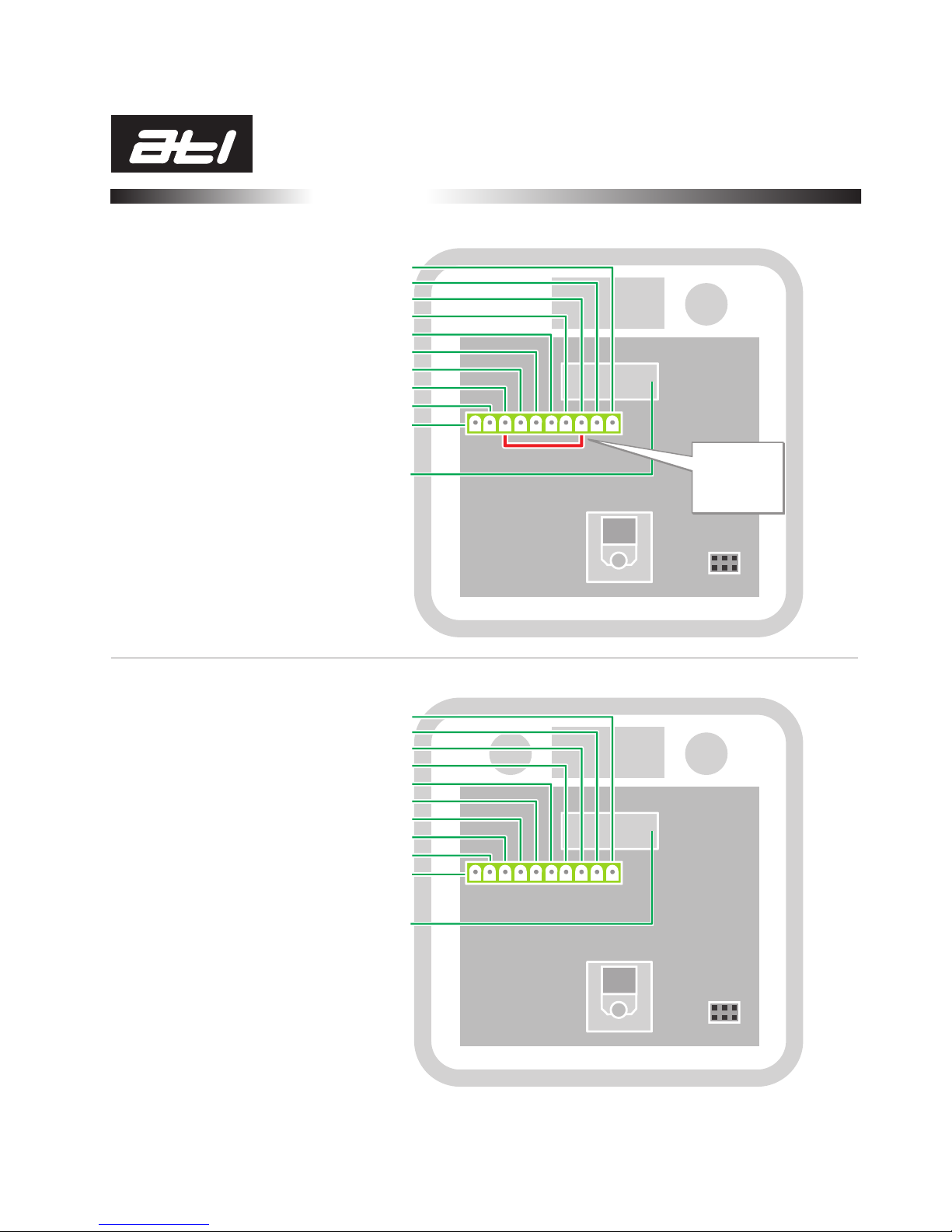
No Connection: 10
No Connection: 9
(+) DC 12volts to Feeder or Solenoid/ Pin 3: 8
(+) DC 12volts from Power Supply: 7
(-) DC 12volts from Power Supply: 6
(-) DC 12volts to Feeder or Solenoid: 5
No Connection: 4
Connect to pin 8: 3
No Connection: 2
Timing Pulse from Power Supply: 1
CHECK: Serial Label displays 12 (volt)
No Connection: 10
No Connection: 9
Left Hand (+) DC 12volts to Feeder or Solenoid: 8
(+) DC 12volts from Power Supply: 7
(-) DC 12volts from Power Supply: 6
Left Hand (-) DC 12volts to Feeder or Solenoid: 5
Right Hand (-) DC 12volts to Feeder or Solenoid: 4
Right Hand (+) DC 12 volts to Feeder or Solenoid: 3
No Connection: 2
Timing Pulse from Power Supply: 1
Single Feeder Connection:
Double Feeder Connections:
*
**
* For abreast feeders connect
to Auto Flap Left Hand
** For abreast feeders connect
to Auto Flap Right Hand
CHECK: Serial Label displays 12 (volt)
1 2 3 4 5 6 7 8 9 10
1 2 3 4 5 6 7 8 9 10
Link connectors
3 and 8
Single Control only
!
© ATL Agricultural Technology Limited: April 2006
 Loading...