

ATI Technologies 100-432001 - RADEON 7500 Multi-monitor Graphics Card, RADEON 7500 Installation Manual
Page 1

ATI RADEON 7500 AGP and PCI
Graphics Controller
Installation Guide
Order Number: EK-R7500-IG. C01
This manual is for managers and operators of
hp AlphaServer systems
with ATI RADEON 7500 AGP and PCI graphics controllers.
Hewlett-Packard Company
Page 2

October 2003
© 2003 Hewlett-Packard Company.
HP shall not be liable for technical or editorial errors or omissions contained herein. The information
in this document is provided “as is” without warranty of any kind and is subject to change without
notice. The warranties for HP products are set forth in the express limited warranty statements
accompanying such products. Nothing herein should be construed as constituting an additional
warranty.
FCC Notice
This equipment generates, uses, and may emit radio frequency energy. The equipment has been type
tested and found to comply with the limits for a Class A digital device pursuant to Part 15 of FCC
rules, which are designed to provide reasonable protection against such radio frequency interference.
Operation of this equipment in a residential area may cause interference in which case the user at his
own expense will be required to take whatever measures may be required to correct the interference.
Any modifications to this device—unless expressly approved by the manufacturer—can void the
user’s authority to operate this equipment under part 15 of the FCC rules.
Modifications
The FCC requires the user to be notified that any changes or modifications made to this device that are
not expressly approved by Hewlett-Packard Company may void the user's authority to operate the
equipment.
Cables
Connections to this device must be made with shielded cables with metallic RFI/EMI connector hoods
in order to maintain compliance with FCC Rules and Regulations.
Taiwanese Notice
ii
Page 3

Japanese Notice
Canadian Notice
This Class A digital apparatus meets all requirements of the Canadian Interference-Causing Equipment
Regulations.
Avis Canadien
Cet appareil numérique de la classe A respecte toutes les exigences du Règlement sur le matériel
brouilleur du Canada.
European Union Notice
Products with the CE Marking comply with both the EMC Directive (89/336/EEC) and the Low
Voltage Directive (73/23/EEC) issued by the Commission of the European Community.
Compliance with these directives implies conformity to the following European Norms (in brackets are
the equivalent international standards):
EN55022 (CISPR 22) - Electromagnetic Interference
EN50082-1 (IEC801-2, IEC801-3, IEC801-4) - Electromagnetic Immunity
EN60950 (IEC950) - Product Safety
Warning!
This is a Class A product. In a domestic environment this product may cause radio interference in
which case the user may be required to take adequate measures.
Achtung!
Dieses ist ein Gerät der Funkstörgrenzwertklasse A. In Wohnbereichen können bei Betrieb dieses
Gerätes Rundfunkstörungen auftreten, in welchen Fällen der Benutzer für entsprechende
Gegenmaßnahmen verantwortlich ist.
Attention!
Ceci est un produit de Classe A. Dans un environnement domestique, ce produit risque de créer des
interférences radioélectriques, il appartiendra alors à l'utilisateur de prendre les mesures spécifiques
appropriées.
Page 4

Page 5

Contents
Preface ...................................................................................................................................xi
Chapter 1 Overview
1.1
Introduction ...........................................................................................................1-1
1.2
Module Description...............................................................................................1-1
1.3
Connector Pinouts..................................................................................................1-4
1.4
Specifications.........................................................................................................1-5
Chapter 2 Installation
2.1
Introduction ...........................................................................................................2-1
2.2
Unpacking..............................................................................................................2-1
2.3
Installation Procedure............................................................................................2-2
Chapter 3 hp Tru64 UNIX Configuration
3.1
Resolutions ............................................................................................................3-1
3.2
Restrictions and Limitations..................................................................................3-2
3.2.1
Minimum Console Revision...........................................................................3-2
3.2.2
Multiple Colormaps........................................................................................3-2
3.2.3
Default Visual Information.............................................................................3-2
3.2.4
Backing Store and Save Unders .....................................................................3-3
3.3
Configuring Graphics Resolution or Vertical Refresh Rate .................................3-4
3.3.1
Current Graphics Resolution..........................................................................3-4
3.3.2
How to Change the Resolution and Refresh Rate...........................................3-4
3.4
Multihead and 3D Support.....................................................................................3-6
3.5
Software Installation..............................................................................................3-7
3.5.1
Installation Preparation and Information........................................................3-7
3.5.2
Installing ATI RADEON 7500 Graphics Support..........................................3-8
3.6
Display Power Management................................................................................3-13
3.7
Messages..............................................................................................................3-13
v
Page 6

Chapter 4 hp OpenVMS Alpha - Graphics Software Installation
and Customization
4.1
Installation Preparation..........................................................................................4-1
4.2
Installation.............................................................................................................4-2
4.2.1
OpenVMS Alpha Version higher than 7.3-1..................................................4-2
4.2.2
OpenVMS Alpha Version 7.3-1.....................................................................4-2
4.3
Video Resolutions Supported................................................................................4-3
4.4
Restrictions and Limitations..................................................................................4-3
4.4.1
Minimum Console Revision...........................................................................4-3
4.4.2
Multiple Colormaps........................................................................................4-3
4.4.3
Single Bit Depth For All Windows ...............................................................4-4
4.4.4
Default Visual Information.............................................................................4-4
4.4.5
NoSupport for Backing Store and Save Unders ..................................4-4
4.4.6
Cloned -Video ................................................................................................4-4
4.4.7
Monitor Support .............................................................................................4-5
4.5
Graphics Configuration .........................................................................................4-5
4.5.1
Default Graphics Settings...............................................................................4-5
4.5.2
Determining Current Settings.........................................................................4-5
4.5.3
Overriding Default Settings............................................................................4-6
4.6
3D Support.............................................................................................................4-7
4.6.1
RADEON 7500 TCL Support........................................................................4-7
4.6.2
Threads Restriction.........................................................................................4-7
4.6.3
No Backing Store/Save Unders for 3D Windows...........................................4-7
4.7
Multiple Graphics Cards Support..........................................................................4-8
4.8
Messages................................................................................................................4-8
4.9
POLYCENTER Software Installation...................................................................4-8
Figures
1-1 ATI RADEON 7500 AGP Graphics Controller....................................................1-2
1-1 ATI RADEON 7500 PCI Graphics Controller......................................................1-3
Tables
1–1 Option Numbers ....................................................................................................1-1
1–2 Standard 15-Pin VGA Connector Pinout...............................................................1-4
1–3 ATI RADEON 7500 AGP Graphics Controller Specifications.............................1-5
1–4 ATI RADEON 7500 PCI Graphics Controller Specifications...............................1-5
vi
Page 7

3–1 Supported Video Modes – Tru64 UNIX................................................................3-1
3–2 Software Option Numbers.....................................................................................3-6
4–1 OpenVMS Version Supporting ATI RADEON 7500 Graphics Controller...........4-2
4–2 Supported Video Modes - OpenVMS....................................................................4-3
vii
Page 8

Page 9

Preface
Intended Audience
This manual is for managers and operators of hp AlphaServer systems with ATI RADEON
7500 AGP and PCI graphics controllers.
Document Structure
This manual has four chapters.
• Chapter 1, Overview, provides a brief overview of the ATI RADEON 7500 AGP and
PCI graphics controllers .
• Chapter 2, Installation, describes the installation of the ATI RADEON 7500 AGP and
PCI graphics controller module in a supported HP product.
• Chapter 3, hp Tru64 UNIX Configuration, describes how to configure the ATI
RADEON 7500 AGP and PCI graphics controller in a system running HP's Tru64
UNIX operating system.
• Chapter 4, hp OpenVMS Alpha - Graphics Software Installation and
Customization, provides information for installing and modifying the software required
to support 2D (two-dimensional) and 3D graphics with the ATI RADEON 7500 AGP
and PCI graphics controllers under the hp OpenVMS Alpha operating system.
Information on the Internet
Visit the AlphaServer Web site at www.hp.com/servers/alphaserver/ for service tools and
more information about ATI RADEON 7500 AGP and PCI graphics controllers.
ix
Page 10

Page 11

Chapter 1
Overview
1.1 Introduction
This chapter provides a brief overview of the ATI RADEON 7500 AGP and PCI graphics
controllers.
1.2 Module Description
The ATI RADEON 7500 AGP graphics controller/accelerator module is a single expansionslot, 32-bit AGP bus graphics option that pr o vides 2D an d 3 D graphics acceleration for
supported HP systems.
The ATI RADEON 7500 PCI graphics controller/accelerator module is a single expansionslot 32 bit, 66/33 MHZ Universal PCI option that provides 2D and 3D graphics acceleration
for supported HP systems.
Both the AGP and PCI graphics cards are based on ATI’s R V20 0 graphics chip.
Table 1–1 Option Numbers
Option Description
3X-PBXGG-AB ATI RADEON 7500 AGP graphics controller with 64 MB of DDR SDRAM
memory, 2D/3D/Multihead software for OpenVMS and Tru64 UNIX
3X-PBXGG-AA ATI RADEON 7500 PCI graphics controller with 64 MB of DDR SDRAM memory,
2D/3D/Multihead software for OpenVMS and Tru64 UNIX
Note: Purchase and Installation of licenses are required to enable 3D features.
Separately orderable part numbers are:
QL-6ZRA9-AA Tru64 UNIX
QL-0ADA9-AA OpenVMS
For up to date minimum operating system and firmware revision information supported for
the ATI RADEON 7500 graphics controllers, refer to the system QuickSpecs located at
http://www.hp.com.
Overview 1-1
Page 12
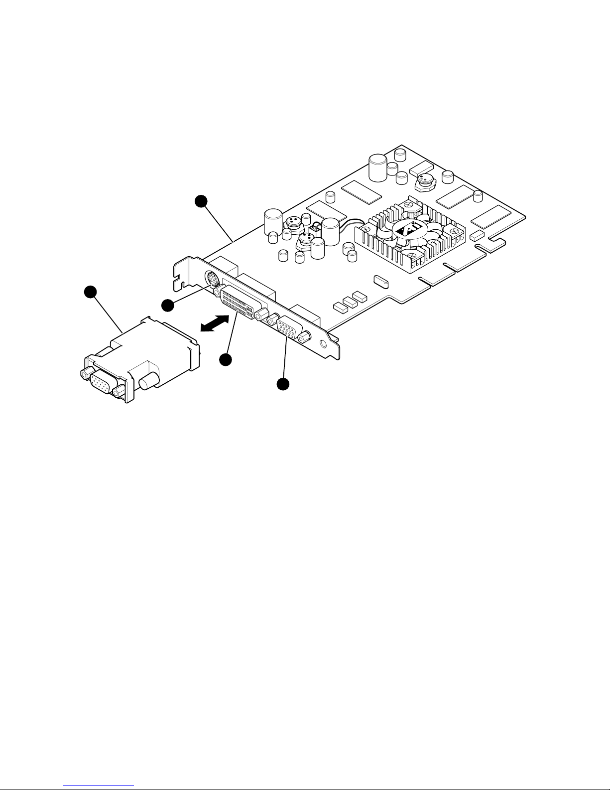
Figure 1-1 ATI RADEON 7500 AGP Graphics Controller
R
S-VIDOUT
DVI
CRT
21900
MR0490
2
1
5
4
3
X
ATI RADEON 7500 AGP graphics controller
Y
DVI-I VGA connector adaptor
Z
S-Video connector
[
DVI-I connector
\
Standard 15-pin VGA connec tor
The ATI RADEON 7500 AGP graphics controller has a standard 15-pin VGA connector, a
DVI-I connector and an S-Video connector. The S-Video functionality is not supported by
Tru64 UNIX or OpenVMS. There is no VGA switch; VGA fu nctions are automatically
configured through the console firmware and software.
1-2 ATI RADEON 7500 AGP and PCI Graphics Controller
Page 13

Figure 1-2 ATI RADEON 7500 PCI Graphics Controller
S-VIDOUT
R
CRT
27300
DVI
MR0494
2
1
5
4
3
X
ATI RADEON 7500 PCI graphics controller
Y
DVI-I VGA connector adaptor
Z
S-Video connector
[
DVI-I connector
\
Standard 15-pin VGA connec tor
The ATI RADEON 7500 PCI graphics controller has a standard 15-pin VGA connector, a
DVI-I connector and an S-Video connector. The S-Video functionality is not supported by
Tru64 UNIX or OpenVMS. There is no VGA switch; VGA fu nctions are automatically
configured through the console firmware and software.
Overview 1-3
Page 14

DVI-I to VGA Connector Adaptor:
Each ATI RADEON 7500 AGP and PCI card is supplied with a connector adaptor for use
on the DVI port so that a standard CRT or LCD monitor with VGA interface can be
connected to the second port on the ATI RADEON 7500. Tru64 UNIX and OpenVMS
require that the DVI-I to VGA connector adaptor supplied with the card always be used.
For information on support for the second port and its use with Tru64 UNIX and OpenVMS
, please see relevant sections in this document and the graphics release notes included on the
software CD .
1.3 Connector Pinouts
Table 1–2 contains a listing of the pins and signals found on the standard 15-pin VGA
connector and the DVI-I to VGA adaptor
Table 1–2 Standard 15-Pin VGA Connector Pinout
Pin No. Signal
1 RED VIDEO
2 GREEN VIDEO
3 BLUE VIDEO
4 No connector
5 GROUND
6 GROUND
7 GROUND
8 GROUND
9 +5V SUPPLY
10 GROUND
11 No connector
12 BI-DIRECTIONAL DATA
13 HORIZONTAL SYNC or COMPOSITE SYNC
14 VERTICAL SYNC (VCLK)
15 DATA CLOCK
1-4 ATI RADEON 7500 AGP and PCI Graphics Controller
Page 15

Chapter 2
Installation
2.1 Introduction
This chapter describes the installation of the ATI RADEON 7500 AGP or PCI graphics
controller module in a supported HP product. Topics included in this chapter are:
• Unpacking
• Hardware installation
2.2 Unpacking
The graphics option hardware is packaged in a single carton that contains one graphic
controller and one installation guide.
Description Part Number
• One ATI RADEON Graphics Controller,
64MB AGP
or
One ATI RADEON Graphics Controller,
64MB PCI
3X-PBXGG-AB
3X-PBXGG-AA
• ATI RADEON 7500 AGP and PCI Graphics
Controller Installation Guide (this manual)
EK-R7500-IG
• DVI-I to VGA connector adapter
209815-001
• Tru64 UNIX graphics software media
QA-6ZRAA-H8
• OpenVMS graphics software m edi a
QA-6ZPAA-H8
Installation 2-1
Page 16

2.3 Installation Procedure
CAUTION: Static electricity can damage sensitive electronic components. When handling
your graphics option, use an anti-static wriststrap that is connected to a grounded
surface on your computer system.
NOTE: Before installing the module, check your monitor specification for signal
compatibility and supported features offered by the ATI RADEON 7500 AGP and
PCI graphics controllers.
The following section describes how to install the ATI RADEON 7500 AGP or PCI graphics
controller. To install the module, perform the following steps:
1. Perform a normal power-down of your computer system and disconnect the monitor
cable.
2. Disconnect all AC power cables from the wall outlet (or turn off the circuit breakers if
applicable to your system) to remove power from the system.
3. Remove the cover from your computer (refer to your system documentation).
4. Put on an anti-static wriststrap.
5. If your computer has an existing graphics module, remove the screw that secures it and
then remove the module.
6. The slot to be selected depends on the graphic controller you are about to install. If your
system had a previously installed graphics option, you can use that expansion slot.
Remove the slot cover if you are using a new slot. Refer to your system owner’s guide
for information about graphics option slots. The AGP card is always installed in the
AGP slot.
7. Grasp the top edge of the graphics option, carefully insert it into the slot, and seat it
firmly.
8. Secure the module with the screw.
9. Replace the computer cover.
10. Ensure that the monitor cable is connected to the video output connector located on the
back of the graphics option.
11. Reconnect the AC power cables to the wall outlet (or turn on th e circuit breakers if
applicable to your system) to restore power to the system.
12. Perform a normal power-up of your computer system.
2-2 ATI RADEON 7500 AGP and PCI Graphics Controllers
Page 17

Chapter 3
hp Tru64 UNIX Configuration
This chapter describes how to configure the ATI RADEON 7500 graphics controller in a
system running the hp Tru64 UNIX operating system.
Chapter 3 pertains to the hp Tru64 UNIX operating system only; if you are running the
OpenVMS operating system, see Chapter 4.
The examples in this manual show version numbers applicable at publication. To determine
the most recent version of the operating system or video driver, see the Release
Notes on the CD-ROM or the HP website at
www.hp.com.
3.1 Resolutions
ATI RADEON 7500 graphics controllers can support various graphics resolutions and
refresh rates as shown in Table 3–1.
Table 3–1 Supported Video Modes – Tru64 UNIX
Resolution
Color Depths
(Bits per Pixel)
Refresh Rates
640x480 8, 16, 24 60, 72, 75, 85 Hz
800x600 8, 16, 24 60, 72, 75, 85 Hz
1024x768 8, 16, 24 60, 70, 75, 85 Hz
1152x864 8, 16, 24 60 Hz
1280x1024 8, 16, 24 60, 75, 85 Hz
1600x1200 8, 16, 24 60, 65, 75, 85 Hz
1920x1440 8, 16, 24 60, 75 Hz
2048x1536 8, 16, 24 60, 65, 70, 75 Hz
3.2 Restrictions and Limitations
This section of the document contains limitations and restrictions of the ATI RADEON
7500 hardware and software.
hp Tru64 UNIX Configuration 3-1
Page 18

3.2.1 Minimum Console Revision
The minimum firmware version for ATI RADEON 7500 graphics controller single head
support is V1.0 on hp AlphaServer GS1280, ES80 and ES47 systems. For other Alpha
System types, please refer to your System QuickSpecs for information on minimum
requirements and restrictions.
3.2.2 Multiple Colormaps
Multiple colormaps are not supported. The ATI RADEON 7500 graphics controllers support
only one installed colormap at one time. Exceeding this limit will cause colormap flashing,
also known as "technicolor."
Applications should not install or de-install colormaps themselves. The window manager
should perform these actions. However, the application is responsible for providing th e
window manager with hints as to which colormaps to install or de-install. You provide this
information using the Xlib function
XSetWMColormapWindows(). This function sets
the WM_COLORMAP_WINDOWS property for a given window.
3.2.3 Default Visual Information
The ATI RADEON 7500 graphics controller can only support one visual type at one time.
Supported default visual types are 8-bit PseudoColor, 16-bit TrueColor, and 24-bit
TrueColor. The default depth and visual class is 24-bit TrueColor. To change the default
visual, you must edit the X server's configuration parameters which are located at
/usr/var/X11/Xserver.conf.
As an example, to switch to 8-bit PseudoColor, do the following:
! RADEON Server args start
-pn -bs -su -depth 8 -vclass PseudoColor
! RADEON Server args end
You then need to restart the X server (you must login remotely or via a serial console):
# /sbin/init.d/xlogin stop
# /sbin/init.d/xlogin start
3-2 ATI RADEON 7500 AGP and PCI Graphics Controllers
Page 19

3.2.4 Backing Store and Save Unders
Backing store and save unders support for the ATI RADEON 7500 is not available in the
Tru64 UNIX base system.
The optional ATI RADEON 7500 Graphi cs Su pp ort software provides backing store a n d
save unders support for 2D operations.
To enable backing store and save unders, remove the "-bs -su" options from the argument
list in the X server configuration file. Refer to the example in Section 3.2.3.
hp Tru64 UNIX Configuration 3-3
Page 20

3.3 Configuring Graphics Resolution or Vertical
Refresh Rate for Tru64 UNIX
Systems use a file named "/usr/var/X11/Xserver.conf" to optionally pass startup
configuration parameters to the X server.
3.3.1 Current Graphics Resolution
The default graphics resolution and refresh rate are 1024x768 at 70Hz, respectively. The
graphics resolution of a running system can be obtained by executing the command
/usr/sbin/sizer -gr. The refresh rate may be obtained from the Xserver’s file /var/dt/Xerrors.
3.3.2 How to Change the Resolution and Refresh Rate
1. Log in to the system as "root".
2. Edit the file
/usr/var/X11/Xserver.conf and add the appropriate X server
option "-screen" and/or "-vsync" to the Xserver’s configuration parameters. (Refer to
the example in Section 3.2.3.)
X server options:
Set screen (W)width and (H)height:
-screen[screen] WxH
Set screen (Hz) Vertical refresh rate:
-vsync[screen] Hz
NOTE: See Table 3–1 for supported resolutions and refresh rates.
When changing the resolution and refresh rate, be sure the parameters specified in
Xserver.conf constitute a valid video mode.
3-4 ATI RADEON 7500 AGP and PCI Graphics Controllers
Page 21

The [screen] number need not be specified if only one screen exists or if the user wants all
screens to use the same values. The [screen] value is generally '0' as shown in the
example below.
Example:
-screen0 1280x1024 –vsync0 75
^ ^
|--[screen] value
-|
Anything added after the "-I" option will be ignored by the Xserver and passed on to the
DDX, Device Dependent X layer of the server. The "-screen" and/or "-vsync"
option(s) should precede the "-I" option.
3. Restart the Xserver (you must login remotely or via a serial console):
# /sbin/init.d/xlogin stop
# /sbin/init.d/xlogin start
Examples of Typical Resolution and Refresh Rate Settings
Setting the vertical refresh rate to 85Hz (the default screen resolut ion wil l be
maintained):
-vsync0 85
Setting the screen resolution to 1280 x 1024 and the vertical refresh rate to 75Hz:
-screen0 1280x1024 –vsync0 75
Setting the screen resolution to 2048 x 1536 (the default vertical refresh rate will be
maintained):
-screen0 2048x1536
hp Tru64 UNIX Configuration 3-5
Page 22

3.4 Multihead and 3D Support
Multihead and 3D support are provided through optional software products as shown in
Table 3-2:
Table 3-2 Software Option Numbers
Option Description
QA-6ZRAA-H8 ATI RADEON 7500 graphics support software for hp Tru64 UNIX
QL-6ZRA9-AA Open3D PAK for ATI RADEON 7500 OpenGL support
The driver included with hp Tru64 UNIX V5.1B supports a sing le ATI RADEON 7500
card, 2D only, and does not support use of the DVI-I port. The optional support software
provides the following additional functions (for further details, features, and restrictions, see
the release notes provided with the kit):
Section 3.5 explains how to install this software.
Multihead (2D only)
Up to 4 ATI RADEON 7500 AGP and/or ATI RADE O N 7 500 PCI car ds can be installed in
one of the supported configurations. Prior to plugging in more than one ATI RADEON
7500 card, you must make sure that your installed SRM console revision level is 6.4 or
above. When the driver detects more than one ATI RADEON 7500 in the system, DMA is
automatically disabled and no 3D is supported. When dual screen mode is enabled with
multiple cards, then only the primary card will have dual screen mode enabled. The SRM
console determines which card is the primary card.
Dual-screen
By default, an ATI RADEON 7500 appears as a single screen device with identical video
signals coming out both the DVI-I and VGA ports. If desired, you can configure your
system so that two screens are created with the signal of the first screen (:0.0) coming out
the VGA port and the signal of the second screen (:0.1) coming out the DVI-I port.
Configuring your system for two screens on the single ATI RADEON 7500 board is
referred to as “dual-screen” mode.
The DVI-I port may be connected only to a VGA monitor through the use of the DVI-I to
VGA connector adapter (p/n 209815-001).
3-6 ATI RADEON 7500 AGP and PCI Graphics Controllers
Page 23

A monitor must be attached to the DVI-I connector at the time the system is powered on;
otherwise there will be no display output to that port.
3D is supported in dual-screen mode so long as DMA is enabled and the resolution of
neither screen is greater than 1280x1024.
OpenGL 3D
The ATI RADEON 7500 Graphics Support kit supports OpenGL V1.2 and GLX V1.2.
Among other features, the kit contains support for the ATI RADEON 7500 TCL hardware,
hardware alpha and stencil planes, 3D multitexturing, and 3D cube map textures.
3.5 Software Installation
This section describes the installation of the ATI RADEON 7500 Graphics Support kit for
the hp Tru64 UNIX operating system. This software is required for multihead, dual-screen,
or 3D graphics support.
This software may be safely installed on a cluster, so long as the ATI RADEON 7500 is the
only type of 3D device in the cluster.
3.5.1 Installation Preparation and Information
Required License (3D operation only)
ATI RADEON 7500 Graphics Support software requires an Open3D Product Authorization
Key (PAK) for OpenGL server operation. This PAK should be registered using the License
Management Facility (LMF) before you install ATI RADEON 7500 Graphics Support. If
you do not register the PAK before starting the software, the server will run in 2D mode
only (without OpenGL server support).
If your ATI RADEON 7500 grap hi cs cont r ol l er hardware and software came pre-installed,
the PAK will already be registered.
For complete information on using the hp Tru64 UNIX License Management Facility, see
the Software License Management guide or the
lmf(8)
reference page.
Prerequisite Software
You can install ATI RADEON 7500 Graphics Support only on systems that are running hp
Tru64 UNIX Version 5.1B or later. hp Tru64 UNIX V5.1B must have Patch Kit 1 or later
patch kits installed before installing the ATI RADEON 7500 Graphics Support software.
The OpenGL graphics support libraries require that the OpenGL Runtime component
(OSFOPENGL540) of the hp Tru64 UNIX V5.1B operating system be installed.
hp Tru64 UNIX Configuration 3-7
Page 24

Before installing ATI RADEON 7500 Graphics Support, you must remove any gra phics
support layered product kits (such as the PowerStorm 300/350 or PowerStorm
4DxxT kits) from the system. After you have installed ATI RADEON 7500
Graphics Support, if you upgrade or reinstall the operating system, you must first
de-install ATI RADEON 7500 Graphics Support. Once the operating system
update has completed, you may reinstall ATI RADEON 7500 Grap hics Support.
Do not install the PowerStorm 300/350, or PowerStorm 4DxxT kit in addition to ATI
RADEON 7500 Graphics Support. Installing any of these kits after installing ATI RADEON
7500 Graphics Support may cause unpredi ctable results.
Alternate Console
Instead of using the graphics display as the system console, it is possible to attach an
external ASCII terminal to serial port 1 and have console interactions take place on that
device. This is done at the boot prompt (>>>).
To use an external terminal, the commands are:
>>> set console serial
>>> init
To return to the graphics display as console, the commands are:
>>> set console graphics
>>> init
3.5.2 Installing ATI RADEON 7500 Graphics Support
You must have super-user (“root”) privileges to perform most operations described below.
Login as root before continuing.
Copying the Kit from CD-ROM
This section describes the procedure for copying the ATI RADEON 7500 Graphics Support
kit from a CD-ROM distribution. The kit is distributed as a tar file with the extension tar.
If you have downloaded the kit from another source, simply copy it into the /var/tmp/
directory and skip to the next section. The installation instructions below assume the name
of the distribution file is RAD540.tar, and that you will be installing on Tru64 UNIX
Version 5.1B. Installation of the kit for other versions will be similar.
In the following instructions, cdrom0 is the CD-ROM disk drive and /mnt is a free
mount point. Follow these instructions to copy the kit from a CD-ROM drive:
1. Place the CD-ROM media in the appropriate disk drive.
2. Mount the media on a free mount point by entering the following command:
# mount -r /dev/disk/cdrom0c /mnt
3-8 ATI RADEON 7500 AGP and PCI Graphics Controllers
Page 25

3. Copy the kit from the CD-ROM to your local hard drive:
# cp /mnt/Tru64_UNIX/RAD540.tar /var/tmp/RAD540.tar
Unpacking the Kit
This section describes the procedure for unpacking the compressed kit into a directory
structure on your local filesystem. It is assumed that the compressed kit distribution file
exists as /var/tmp/RAD540.tar.
1. Change to the directory where you copied the kit distribution file:
# cd /var/tmp
2. Use tar to unpack the tar file into a directory structure:
# tar xvf RAD540.tar
This will create the RAD540 directory and populate it with the kit files.
hp Tru64 UNIX Configuration 3-9
Page 26

Installing the Kit
This section describes the procedure for installing ATI RADEON 7500 Graphics Support. It
is assumed that the kit has been obtained and unpacked into the /var/tmp/RAD540/
directory.
1. Ensure that the system in which you wish to install ATI RADEON 7500 Graphics
Support does not already contain a graphics support kit.
To determine if graphics support subsets are installed on the system, enter the
command:
# setld -i | grep –e O3D -e 3X0 -e 4DT | grep installed
If any of these subsets are installed, you must de-install them using the setld –d
command. For example, to remove the PowerStorm 3x0 V2.3 files, you might enter:
# setld -d 3X0CONFIG524 3X0DEVICE524 3X0GLBASE524
2. Make sure that you are in the directory where you unp acked the kit:
# cd /var/tmp/RAD540/
3. Start the installation.
Start the installation by entering the setld command with the -l (load) function,
specifying the current directory as the location of the kit:
# setld -l .
4. Specify the subsets you wish to install.
The installation procedure displays the list of subsets available for installation and
prompts you to choose the desired subsets.
*** Enter subset selections ***
The following subsets are mandatory and will be installed automatically
unless you choose to exit without installing any subsets:
* ATI RADEON V1.0 for V5.1B Config
* ATI RADEON V1.0 for V5.1B Device
The subsets listed below are optional:
There may be more optional subsets than can be presented on a single
screen. If this is the case, you can choose subsets screen by screen
or all at once on the last screen. All of the choices you make will
be collected for your confirmation before any subsets are installed.
- Other:
* ATI RADEON V1.0 for V5.1B OpenGL
Or you may choose one of the following options:
2) ALL mandatory and all optional subsets
3) MANDATORY subsets only
3-10 ATI RADEON 7500 AGP and PCI Graphics Controllers
Page 27

4) CANCEL selections and redisplay menus
5) EXIT without installing any subsets
Estimated free diskspace(MB) in root:382.2 usr:3507.8
Enter your choices or press RETURN to redisplay menus.
Choices (for example, 1 2 4-6):2
5. Confirm your subset selection.
The installation procedure displays a list of the subsets you selected.
You are installing the following mandatory subsets:
ATI RADEON V1.0 for V5.1B Config
ATI RADEON V1.0 for V5.1B Device
You are installing the following optional subsets:
- Other:
ATI RADEON V1.0 for V5.1B OpenGL
Estimated free diskspace(MB) in root:382.2 usr:3502.1
Is this correct? (y/n):
Enter ‘y’ if the subsets you wish to install are those listed. Enter ‘n’ to specify other
subsets.
6. Read the informational messages.
The installation procedure generates messages as it checks that your system has enough
space to install the requested subsets, copies these subsets, and then verifies that they
were copied correctly.
File system space checked OK.
3 subsets will be installed.
Loading subset 1 of 3 ...
ATI RADEON V1.0 for V5.1B Device
Copying from . (disk)
Verifying
Loading subset 2 of 3 ...
ATI RADEON V1.0 for V5.1B OpenGL
Copying from . (disk)
Verifying
Loading subset 3 of 3 ...
ATI RADEON V1.0 for V5.1B Config
Copying from . (disk)
Verifying
3 of 3 subsets installed successfully.
Saved file ./usr/shlib/X11/libfb.so as ./usr/shlib/X11/libfb.so.pre.RAD540
hp Tru64 UNIX Configuration 3-11
Page 28

Saved file ./usr/shlib/X11/lib_dec_RADEON.so as
./usr/shlib/X11/lib_dec_RADEON.so.pre.RAD540
Configuring "ATI RADEON V1.0 for V5.1B Device (RADDEVICE540)
Configuring "ATI RADEON V1.0 for V5.1B OpenGL (RADGLBASE540)
Configuring "ATI RADEON V1.0 for V5.1B Config (RADCONFIG540)
**** Creating Context Dependent Symbolic Links ****
New CDSL: ./usr/shlib/radeon_dri.so ->
/cluster/members/{memb}/./usr/shlib/radeon_dri.so ->
/usr/opt/RAD540/./usr/shlib/radeon_dri.so
New CDSL: ./usr/shlib/X11/lib_dec_acc_glx.so ->
/cluster/members/{memb}/./usr/shlib/X11/lib_dec_acc_glx.so ->
/usr/opt/RAD540/./usr/shlib/X11/lib_dec_acc_glx.so
New CDSL: ./usr/shlib/X11/lib_dec_swGL_GLX.so ->
/cluster/members/{memb}/./usr/shlib/X11/lib_dec_swGL_GLX.so->
/usr/opt/RAD540/./usr/shlib/X11/lib_dec_swGL_GLX.so
New CDSL: ./usr/shlib/X11/lib_dec_drm.so ->
/cluster/members/{memb}/./usr/shlib/X11/lib_dec_drm.so ->
/usr/opt/RAD540/./usr/shlib/X11/lib_dec_drm.so
New CDSL: ./usr/shlib/X11/lib_dec_dri.so ->
/cluster/members/{memb}/./usr/shlib/X11/lib_dec_dri.so ->
/usr/opt/RAD540/./usr/shlib/X11/lib_dec_dri.so
New CDSL: ./usr/shlib/X11/lib_dec_radeon_gl.so ->
/cluster/members/{memb}/./usr/shlib/X11/lib_dec_radeon_gl.so ->
/usr/opt/RAD540/./usr/shlib/X11/lib_dec_radeon_gl.so
Removing obsolete 3D device clauses from node NODENAME
Xserver.conf...
Adding ATI RADEON clauses to node NODENAME Xserver.conf...
Release notes can be found in the /usr/opt/RAD540/ReleaseNotes/
directory.
**** Auto Kernel Configuration ****
*** KERNEL CONFIGURATION AND BUILD PROCEDURE ***
Saving /sys/conf/NODENAME as /sys/conf/NODENAME.bck
*** PERFORMING KERNEL BUILD ***
Working.... Mon Feb 3 14:51:25 EST 2003
The new kernel is /sys/NODENAME/vmunix
Copying new kernel to /vmunix...
Installation of RADCONFIG540 Complete.
**** SHUTDOWN and POWER-CYCLE to enable new kernel ****
3-12 ATI RADEON 7500 AGP and PCI Graphics Controllers
Page 29

7. Dismount the CD-ROM drive from the mount point.
For example, to dismount mount point /mnt, enter the command:
# umount /mnt
8. Remove the CD from the CD-ROM drive.
9. Shutdown and power-cycle the system.
The installation is now completed.
3.6 Display Power Management
On a workstation, display power management is enabled by default. On a server, it is
disabled by default. To enable display power management on a server, edit the X server
configuration file (/usr/var/X11/Xserver.conf) and add the "dpms" option to the
argument list. Refer to the example in Section 3.2.3.
Display power management dwell times can be set via the dpms option of the xset
command.
3.7 Messages
Device driver messages are typically logged to /var/adm/messages on Tru64 UNIX
systems. Should problems arise, this file should be checked for informational messages; an
example is shown here.
Radeon0: 100x100 cursor glyph truncated to hardware limits
The X server attempted to use a cursor larger than the 64x64 limits of the hardware. Cursor
glyph will be displayed incorrectly. Application should be brought into conformance with
X11 expectations.
Additional informational and error messages are logged by the Xserver in
/var/dt/Xerrors.
hp Tru64 UNIX Configuration 3-13
Page 30

Page 31

Chapter 4
hp OpenVMS Alpha - Graphics
Software Installation and
Customization
This chapter provides information for installing and modifying the software required to
support 2D (two-dimensional) and 3D graphics with the ATI RADEON 7500 AGP and PCI
graphics controllers under the hp OpenVMS Alpha operating system.
The method used to load the software is directly dependent on the version of OpenVMS
Alpha that you will be installing or upgrading to. Section 4.2, Installation, explains in detail
the steps that must be taken for each of the different OpenVMS Alpha versions.
The behavior of the ATI RADEON 7500 AGP and PCI graphics controllers’ support
software may be modified after installation on OpenVMS by editing the appropriate files
and issuing DCL commands. (See Section 4.5.3.)
4.1 Installation Preparation
This section describes how to prepare for installation of the ATI RADEON 7500 AGP and
PCI graphics controller support software.
The ATI RADEON 7500 AGP and PCI graphics controller support software is installable on
OpenVMS Alpha Version 7.3-1 and higher.
Table 4–1 provides information on OpenVMS support for the ATI RADEON 7500 graphics
controllers. The software to support the ATI RADEON 7500 graphics controllers will be
fully integrated into future releases of OpenVMS Alpha. The ATI RADEON 7500 graphics
controllers are not support e d on Ope nVM S versions prior to 7.3-1.
hp OpenVMS Alpha - Graphics Software Installation and Customization 4-1
Page 32

Table 4–1 OpenVMS Version Supporting ATI RADEON 7500 Graphics
Controller
OpenVMS
Version
Alpha Platform
7.3-1
Copy the POLYCENTER Software Installation patch kits from net
location http://www.support.HP.com/patches/*
OR
Copy the patch kits by anonymous ftp at http://ftp1.support.HP.com in
VMS version specific subdirectories of /public/vms/axp/
Prior to 7.3-1 Not supported.
*Caution: The required list of patch kits for a particular version of OpenVMS can vary over time.
Check the Readme files and/or Release notes associated with each of the kits to be sure that the patch
kit is appropriate for your usage.
4.2 Installation
This section covers installation of the ATI RADEON 7500 graphics controllers’ support
software on various versions of the OpenVMS Alpha operating system.
4.2.1 OpenVMS Alpha Version higher than 7.3-1
For OpenVMS Alpha Version higher than 7.3-1, the ATI RADEON 7500 graphics
controller support software is loaded automatically following installation and becomes
active when the operating system is booted. No other action needs to be taken by the system
operator.
4.2.2 OpenVMS Alpha Version 7.3-1
The ATI RADEON 7500 graphics cont r ol l er is not su p po rt ed on any OpenVMS Alpha
Version prior to 7.3-1.
To install the ATI RADEON 7500 graphics controller support software on OpenV MS Alpha
Version 7.3-1, you must copy the latest UPDATE and GRAPHICS POLYCENTER
Software Installation utility patch kits from the World Wide Web location at
http://www.support.HP.com/patches/ or via anonymous ftp at ftp1.support.HP.com. Then,
use the POLYCENTER Software Installation utility (DCL PRODUCT INSTALL) to install
the latest UPDATE kit and the latest GRAPHICS kit, if required. View the Readme files for
each kit to determine if the UPDATE kit has superseded the GRAPHICS kit or if the
GRAPHICS kit is newer than the UPDATE kit.
For more information on using POLYCENTER Software Installation utility, see the
POLYCENTER Software Installation Utility User’s Guide.
4-2 ATI RADEON 7500 AGP and PCI Graphics Controllers
Page 33

4.3 Video Resolutions Supported
The ATI RADEON 7500 AGP and PCI graphics controllers are capable of supporting the
graphics resolutions, color depths, and refresh rates shown in Table 4–2.
Table 4–2 Supported Video Modes - OpenVMS
Resolution
Color Depths
(Bits per Pixel)
Refresh Rates
(Hertz)
640 x 480 8, 16, 24 60, 72, 75, 85
800 x 600 8, 16, 24 60, 72, 75, 85
1024 x 768 8, 16, 24 60, 70, 75, 85
1152 x 864 8, 16, 24 60
1280 x 1024 8, 16, 24 60, 75, 85
1600 x 1200 8, 16, 24 60, 65, 75, 85
1920 x 1440 8, 16, 24 60, 75
2048 x 1536 8, 16, 24 60, 65, 70, 75
The mode chosen should match your monitor capabilities. In general, refresh rates below
70 Hz are discouraged, as they tend to show flicker based on the lighting source and
surrounding equipment.
The available resolution is monitor dependent. The default video mode is 1024X768
@70HZ and 24 bits per pixel color depth.
4.4 Restrictions and Limitations
This section of the document contains limitations and restrictions of the ATI RADEON
7500 hardware and software.
4.4.1 Minimum Console Revision
The minimum console firmware version for support of the ATI RADEON 7500 graphics
controller under OpenVMS Alpha is system dependent. Please consult your platform option
information for minimum requirements.
4.4.2 Multiple Colormaps
Multiple colormaps are not supported. The ATI RADEON 7500 AGP and PCI graphics
controllers support only one installed colormap at one time. Exceeding this limit will cause
colormap flashing, also known as "technicolor."
Applications should not install or de-install colormaps themselves. The window manager
should perform these actions. However, the application is responsible for providing the
hp OpenVMS Alpha - Graphics Software Installation and Customization 4-3
Page 34

window manager with hints as to which colormaps to install or deinstall. You provide this
information using the Xlib function XSetWMColormapWindows(). This function sets the
WM_COLORMAP_WINDOWS property for a given window.
4.4.3 Single Bit Depth For All Windows
With the RADEON 7500, all windows created on a particular head must have the same bit
depth. The RADEON 7500 support s bit de p t hs of 8, 16, and 24 bit s per pi xel on any
graphics head, but once the DECwindows server establishes a bit depth on a particular head,
only windows or visuals with that bit de pth can be created.
4.4.4 Default Visual Information
The ATI RADEON 7500 board can only support one visual type at one time. Supported
visual types are 8-bit PseudoColor, 16-bit TrueColor, and 24-bit TrueColor. By default, the
default depth and visual class is 24 bit TrueColor.
To change the default visual, you must assign a value (or a comma separated list of values
for multiple graphics cards) to the symbolic name
DECW$SERVER_DEFAULT_VISUAL_CLASS in the DCL procedure
SYS$MANAGER:DECW$PRIVATE_SERVER_SETUP.COM (the acceptable values and
their meanings are listed in the procedure). To change the pixel depth, edit
DECW$PRIVATE_SERVER_SETUP.COM and define the executive-mode logical name
DECW$SERVER_PIXEL_DEPTH in the system logical name table (this may also be a
comma-separated list for multiple graphics cards).
As an example, to switch to 24-bit TrueColor, add the following lines to
SYS$MANAGER:DECW$PRIVATE_SERVER_SETUP.COM:
$ DECW$SERVER_DEFAULT_VISUAL_CLASS :== 24
$ DEFINE/EXEC/SYSTEM/NOLOG DECW$SERVER_PIXEL_DEPTH 24
You then need to restart the X server. Refer to Section 4.5.3 for more information on
changing default settings and restarting the X server.
4.4.5 No Support for Backing Store and Save Unders
Backing store and save unders are not supported in the Radeon 7500 X server on OpenVMS
version 7.3-1. This feature will be supported in the next Graphics update kit. Refer to the
Release Notes associated with the version you are installing for updated information.
4.4.6 Cloned -Video
If you have monitors connected to both the DVI port and VGA port when you power up the
system, identical video output is displayed on both the monitors. This also applies to the first
card on a muti-card configuration. The DVI ports on subsequent cards are disabled.
4-4 ATI RADEON 7500 AGP and PCI Graphics Controllers
Page 35

4.4.7 Monitor Support
The RADEON 7500 card has two built-in video connectors: an analog VGA connector and a
DVI-I connector. You can plug analog monitors or flat panel monitors with VGA interface
into the RADEON 7500 card’s video connectors.
Only analog interface on DVI connector is supported. The DVI-I to VGA connector adapter
supplied with the RADEON 7500 card must be installed on the card to connect a monitor to
that port. The monitor(s) you plan to use must already be plugged into the RADEON 7500
card when you power cycle your machine or when you initialize from the system Console.
4.5 Graphics Configuration
4.5.1 Default Graphics Settings
The default graphics resolution is 1 024 x 7 6 8. The defa ul t ref resh rate is 70 Hz . The de faul t
color depth is 24 bits per pixel and the default visual type is TrueColor.
4.5.2 Determining Current Settings
To find the current settings under OpenVMS, issue the following commands, in order, at the
DCL prompt:
$ @decw$utils:decw$define_utils
$ xdpyinfo
In addition, you can show the following logical names at the DCL prompt:
$ SHOW LOGICAL/SYSTEM DECW$SERVER_PIXEL_DEPTH
$ SHOW LOGICAL/SYSTEM DECW$SERVER_REFRESH_RATE
$ SHOW LOGICAL/TABLE=DECW$SERVER* DECW$XSIZE_IN_PIXELS
$ SHOW LOGICAL/TABLE=DECW$SERVER* DECW$YSIZE_IN_PIXELS
$ SHOW LOGICAL/TABLE=DECW$SERVER* DECW$SERVER_DEFAULT_VISUAL_CLASS
If any logical name is not defined, then the respective default is in effect
(see Section 4.5.1).
Alternatively, you can also view the following error log file to determine
current settings:
$ TYPE SYS$MANAGER:DECW$SERVER_0_ERROR.LOG
hp OpenVMS Alpha - Graphics Software Installation and Customization 4-5
Page 36

4.5.3 Overriding Default Settings
To override any of the default settings, follow these steps:
1. Copy or rename the
SYS$MANAGER:DECW$PRIVATE_SERVER_SETUP.TEMPLATE file to create a
new command (.com) file called DECW$PRIVATE_SERVER_SETUP.COM.
2. Now make the edits for the settings you want to change using a text editor, and save the
file.
3. For the changes to take effect immediately you must restart the X server so that the new
command file and changed settings will be used. The command to do this is as follows:
$ @SYS$MANAGER:DECW$STARTUP RESTART
The new file settings will now override the original default settings.
The DECW$PRIVATE_SERVER_ SET UP pr ocedure contains documentat i on fo r m a ny of
the default X server settings that may be changed. For more information on making changes
to the default settings, symbols, and system-wide logicals, refer to the manual titled
Managing DECwindows Motif for OpenVMS Systems. This document describes the
symbols and settings that can be changed in the DECW$PRIVATE_SERVER_SETUP.COM
file. For a copy of the document, contact your local sales support representative or visit the
HP Web site located at http://www.hp.com.
Additional system logicals are described in
SYS$MANAGER:DECW$DEVICE_CONFIG_GH.COM.
However, this file should not be modified. If you wish to make changes to the default
logicals defined within it, redefine them in the DECW$PRIVATE_SERVER_SETUP.COM
file. These changes will supersede the logicals assigned in the device configuration file.
Some of the items that you can change via system logicals are described in the device
configuration file but are not normally defined in
DECW$PRIVATE_SERVER_SETUP.COM file. Those logical default settings include the
following items:
DECW$XSIZE_IN_PIXELS
DECW$YSIZE_IN_PIXELS
DECW$SERVER_REFRESH_RATE
DECW$SERVER_PIXEL_DEPTH
4-6 ATI RADEON 7500 AGP and PCI Graphics Controllers
Page 37

4.6 3D Support
To get the most out of your RADEON 7500 graphic contro ller, you must have an Open3D
license to use the 3D hardware-acceleration (direct rende ring) features supported by this
product.
The ATI RADEON 7500 Graphics Support kit supports the 3D graphics library OpenGL
V1.2 and GLX V1.2. Among other features, the kit contains support for the ATI RADEON
7500 TCL hardware, hardware alpha and stencil planes, 3D multitexturing, and 3D cube
map textures.
If you have an Open3D license, OpenGL software for RADEON 7500 will, by default, force
a direct-rendered OpenGL rendering context whenever the OpenGL client requests
connectio n to the DECwindows server using the LOCAL t ransport.
You can override this default behavior and force the default to always be indirect rendering
by defining the following logical name before running the 3D application:
$ DEFINE LIBGL_ALWAYS_INDIRECT 1
4.6.1 RADEON 7500 TCL Support
The OpenGL driver for the RADEON 7500 contains support for the on-board
transformation, clipping, and lighting (TCL) hardware of the RADEON 7500 for increased
primitive rendering performance. You can take advantage of these capabilities if you have
an Open3D license.
4.6.2 Threads Restriction
The RADEON 7500 OpenGL library for OpenVMS is not thread safe. However, OpenGL
can be used in a multithreaded program if the use of OpenGL is restricted to a single thread
within the program.
4.6.3 No Backing Store/Save Unders for 3D Windows
Backing store and save under features are not supported when 3D is enabled.
hp OpenVMS Alpha - Graphics Software Installation and Customization 4-7
Page 38

4.7 Multiple Graphics Cards Support
V0300 and later releases of the Radeon software supports up to 4 Radeon cards per system.
You could have one AGP and 3 PCI cards – or you could have 1 to 4 PCI cards. All
operations, including hardware accelerated 3D graphics, are supported on every card in the
system. Consult your Alpha system options documentation for detailed information on
number of cards supported and configuration limitations.
4.7.1 Matching Primary Screen with VGA console
Screen 0 is always the VGA-enabled head and must be installed in the lowest numbered slot
of all installed graphics cards.
If you wish to change a screen with any of the console displays, you alter the logical order
for mapping of physical screens to logical screens by making a copy of the file
DECW$PRIVATE_SERVER_SETUP.TEMPLATE and saving it to a new file named
DECW$PRIVATE_SERVER_SETUP.COM. You can then make changes to the default
settings by editing the newly created file.
4.8 Messages
Server messages are typically logged to the DECW$SERVER_0_ERROR.LOG file located in
the SYS$MANAGER directory. Be sure to check this file first for messages related to
problems encountered during installation or usage.
4.9 POLYCENTER Software Installation
At the end of the OpenVMS POLYCENTER software installation procedure, a message is
displayed that recommends a reboot of the system. At the conclusion of the installation, the
POLYCENTER software installation utility does not prompt for or enforce a reboot of the
system for the new software image to become effective immediately. The ATI RADEON
7500 AGP and PCI graphics controllers’ two-dimensional (2D) support software becomes
active only after the operating system has been rebooted.
If the software is being installed in a clustered environment and it is not convenient to
perform a reboot immediately following installation, then a rolling reboot may be used for
the new image to take effect across all systems.
4-8 ATI RADEON 7500 AGP and PCI Graphics Controllers
 Loading...