

A & T International 1 Service Manual
CHILLED WATER
CEILING-SUSPENDED
AND HIGH-WALL
AIR HANDLERS
Installation, Operation and
Maintenance Manual
An ISO 9001-2008 Certied Company
CEILING-SUSPENDED AIR HANDLER
(CCP)
HIGH-WALL AIR HANDLER (WCP)
ECR International, Inc.
2201 Dwyer Avenue,
Utica NY 13501
web site: www.ecrinternational.com
P/N# 240004373, Rev. B [07/15/2013]
TABLE OF CONTENTS
Important Safety Information ........................................................................................... 3
General Product Information ............................................................................................4
EMI Air Handler Family ....................................................................................................4
Installer Supplied Items .................................................................................................. 4
Controls And Components ......................................................................................................... 5
High Volt Electrical Wiring ................................................................................................ 5
Low Volt Interconnect .....................................................................................................6
DIP Switch Settings .................................................................................................................. 7
Ceiling-Suspended Air Handler CCP ................................................................................... 8
Ceiling-Suspended Air Handler WCP ................................................................................ 10
Start Up Preparation ..................................................................................................... 13
Start-up for Unit Mounted
Fan Operation .............................................................................................................. 14
High-Wall Thermostat Control Start-Up ............................................................................16
Maintenance ................................................................................................................ 18
........................................................................................................14
Troubleshooting ............................................................................................................ 18
Troubleshooting Procedure - Error Codes ...................................................................... 20
Warranty ................................................................................................................... 21
Report Shipping Damage Carrier
Examine exterior. Remove cover and examine compressor
and piping for signs of damage.
Installer:
When requesting assistance, please have following
information available:
Model Number_________________________
(1) Retain this manual and warranty for future reference.
(2) Before leaving the premises, review this manual to be
sure the unit has been installed correctly and run the unit
for one complete cycle to make sure it functions properly.
Unit has been tested and
rated in accordance with:
ANSI/AHRI Standards
440-2008
UL-1995
Serial Number_________________________
Date of installation______________________
Check our website frequently for updates: www.enviromaster.com
Information and specications outlined in this manual in effect at the
time of printing of this manual. Manufacturer reserves the right to
discontinue, change specications or system design at any time without
notice and without incurring any obligation, whatsoever.
2
IMPORTANT SAFETY INFORMATION
!
WARNING
Electrical shock hazard. Improper assembly and/
or installation could result in death or serious injury.
Have a qualied service agency install and service
this appliance. Read this manual and understand all
requirements before beginning installation.
WARNING
!
• Install or locate this unit only in accordance with
instructions found in this manual. Use this unit
only for its intended purpose as described in this
manual.
• Connect EMI air handler to properly grounded
electrical supply. Do not fail to properly ground
this unit.
• Turn off electrical supply before servicing the EMI
air handler.
• Do not use EMI air handler if it has damaged
wiring, is not working properly, or has been
damaged or dropped.
!
WARNING
Tampering with this unit is dangerous and could
result in serious injury or death. Do not modify or
change this unit.
Safety Information
• Have a qualied service agency install and service this
appliance.
• Turn off electrical supply before servicing unit.
• Inspect all parts for damage prior to installation and
start-up.
• Do not use unit if it has damaged wiring, is not working
properly, or has been damaged or dropped.
• Connect to properly grounded electrical supply with
proper voltage as stated on rating plate.
• Have proper over-current protection (i.e. time-delay
fuse/HACR Breaker) as listed on Rating Plate.
• Verify there are no power feeds to unit such as re
alarm circuits, BMS circuits, etc.
• Service or repair of unit using manufacturer approved
replacement parts only.
Become Familiar With Symbols
Identifying Potential Hazards.
!
DANGER
Indicates a hazardous situation which, if not
avoided, WILL result in death or serious injury.
!
WARNING
Indicates a hazardous situation which, if not
avoided, could result in death or serious injury.
!
CAUTION
Indicates a hazardous situation which, if not
avoided, could result in minor or moderate injury.
NOTICE
• Do not use any mechanical or electrical controllers which
have been wet. Replace any defective controller.
• Do not support any part of ceiling with appliance,
associated wiring or pipe work.
• Check rating plate on unit before installation. Verify
voltage shown is same as electric supply to unit. Rating
plate is located on top panel.
Indicates information which should be followed to
ensure proper installation and operation.
3

GENERAL PRODUCT INFORMATION
EMI Air Handler Family
Materials of Construction:
1.
Cabinet fabricated of 20-gauge galvanneal steel with
off-white powder coat matte nish.
2.
Plastic tops, fronts constructed of high impact
polystyrene (Hips) material.
3.
Discharge grill construction of high temperature Noryl
plastic (WCP ONLY).
• Annodized Aluminum discharge grill CCP.
4.
Condensate drain pan constructed of anticorrosive
G90U galvanized steel.
EMI Air Handler is available as wall or ceiling unit two-pipe
chilled water fan coil model. Air handler offers ease of
installation, operation, and service. Presently, EMI does
not offer a chiller unit that provides chilled water for WCP
and CCP models.
EMI Ductless Split System
Air Handler Family Consists Of:
Installer Supplied Items
• Low voltage wiring (18 awg required)
• High voltage power supply wiring
• Mounting fasteners (screws, wall anchors, etc.)
• Chilled water, condensate piping
• Hot water piping
WCP: Two-pipe chilled water fan coil wall unit available in
12,000, 18,000, and 30,000 nominal Btuh capacities (hot
water coil not available).
CCP: Two-pipe chilled water and optional hydronic heat fan
coil ceiling units available in 12,000, 24,000, 30,000 and
48,000 nominal Btuh capacities.
EMI Air Handlers are tested and rated in accordance with
UL 1995.
4

GENERAL PRODUCT INFORMATION
Installation Considerations
• Determine best location for mounting unit for room air
circulation.
• Determine how power wire (high and low voltage)
condensate drainage, and water supply piping may be
run to and from unit. Knockouts on air handler may be
used for this purpose.
• Consider serviceability when locating unit. Cabinet
service panels must be able to be removed without
obstruction.
• CCP - units can be equipped with hot water coil.
Controls And Components Factory Installed Or
Supplied
Unit mount control panel includes:
• ¾” backlit LCD display
• Adjustable operational range from 55° F to 95° F (in one-
degree increments)
• 60 second fan purge
• Freeze protection
• Audio feedback on control setting changes
Fan operation: Auto (cycling), High and Low (constant)
• Dry Mode (operates cooling and electric heat simultaneously
to remove humidity when optional electric heat is selected)
• Test Operation for ease of testing after installation (all
timers reduced)
• Non-volatile Backup Memory (control settings maintained
indenitely during power outages)
• 24V Low Voltage Transformer
High Volt Electrical Wiring
(SEE THE APPROPRIATE AIR HANDLER SECTION FOR SPECIFIC
WIRING INFORMATION.)
All wiring shall be in accordance with the National Electric Code
(NEC) and local building codes.
1.
Inspect existing wiring for any deciencies such as cut
or frayed wires. Replace such wiring if found.
2.
Check unit rating plate for circuit ampacity and breaker
or fuse size. Use only HACR type breakers. Select
proper wire for ampacity rating.
3.
Each unit must have separate branch circuit protected
by fuse or breaker. Refer to unit rating plate for proper
wire and breaker or fuse size.
4.
Connect power wire to Black (L1) and other wire to
Red/White (L2) at power connector location. Connect
ground wire to ground lug or lead at same location in
control box.
On units rated 208/230V, primary side of transformer is
factory wired for 230V. For 208V power supply, transformer
tap must be changed from orange to red. Refer to wiring
diagram located on unit.
IMPORTANT: When wiring WCP 18–30 only: If job site
voltage is 208V, WCP high-low fan speed switch may be
rewired to increase air speed. Replace black and red fan
motor wire connections with blue and orange fan motor
wires respectively.
details.
See unit wire diagram for specic
IMPORTANT: Unit mounted controls are fully functional
without the hand-held remote. See page 5
Optional Controls & Components
• Infrared hand held remote control
• Condensate pump (eld or factory installed)
• Chilled water control valve (eld installed)
• Wiring for normally closed/power open valve (24V
AC, 20VA max. or 8VA max. on units with condensate
pumps)
• Open wire electric heaters in 3 sizes (factory
installed ONLY) with automatic reset high
temperature cutout and redundant high temperature
fuse link
• Hydronic heat coil with sweat connections (consult
factory) CCP only
• 24VAC wall thermostat compatibility
5
LOW VOLT INTERCONNECT WIRING FOR UNIT MOUNTED CONTROLS
24V control transformer is located in air handler unit. This
provides low volt control power to air handler . Depending on
models selected, low Volt interconnect control wiring may be
effected.
Note: All low volt interconnect wiring must be at
least 18 awg.
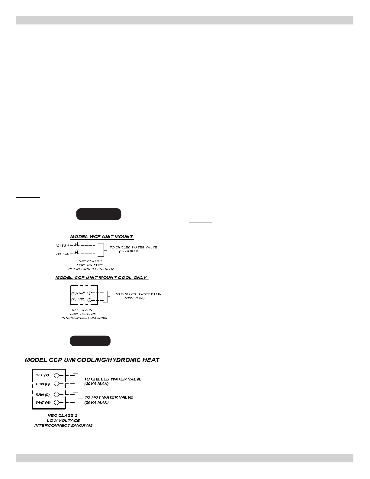
COOLING ONLY UNITS With or Without Heat
Cooling only units utilize two low Volt interconnecting wires
between the indoor and outdoor units. Wires (WCP) or terminals
(CCP) designated “Y” (yellow) and “C” (brown) of the air handler
should be connected to the corresponding “Y” (yellow) and “C”
(brown) wires or terminals of the condenser. Other wires or
terminals such as “R” (red) or “O” (orange) may not be needed
and should be protected by a wire nut from making contact with
the junction box or other metal surfaces.
Refer to low Volt interconnect diagram interconnect diagram
Figure 1 for unit mounted controls.
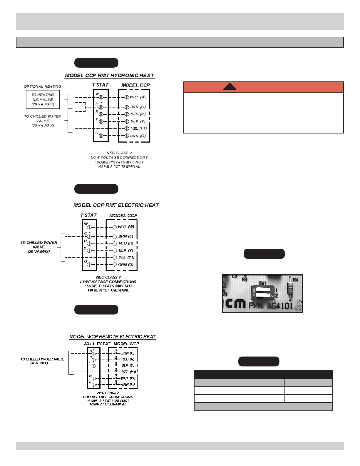
Remote Thermostat Controls
24V control transformer is located in air handler unit. This
provides low volt control power to air handler. Depending on
models selected, interconnect control wiring may be effected.
All low Volt interconnect wiring must be at least 18
awg.
Choosing Remote High-Wall Thermostat: See “Wall
Thermostat Control” section Pg. 15-16
COOLING ONLY UNITS With or Without Heat
Depending on the thermostat required or selected, cooling only
air handles may utilize four to six low Volt interconnecting wires
between the indoor unit and thermostat. Some thermostats do
not require the use of the “C” (brown) connection. In this case,
ensure that any unused wires are insulated with a wire nut to
prevent them from making contact with the junction box or other
metal surfaces.
If the indoor unit has electric heat or hydronic heat then a “W”
connection is required between the thermostat and indoor unit.
Figure 1
Figure 1A
Refer to low Volt interconnect diagram interconnect diagram
Figure 2 for remote wall thermostat controls
6
COMMON TO ALL AIR HANDLERS CONTINUED
(SEE PAGE 13 FOR SEQUENCE OF OPERATION)
DIP SWITCH SETTINGS (Unit Mount Control Only)
There are two dip switches on the relay board that offer
Figure 2
different modes of operation. This allows unit to be
matched with either cooling only or cooling with electric
heat.
!
WARNING
Electrical shock hazard. Before accessing control
compartment, disconnect power to indoor unit.
NOT change dipswitch settings with power
applied to unit.
Failure to follow these instructions
could result in death or serious injury.
WCP- to gain access to relay board, remove return air grill
from front of unit. Remove any panels or covers to control
section. The relay board is located in control box of unit.
Set dipswitches (Figure 3) according to table below(Figure
4).
DO
Figure 2 A
Figure 2 B
CCP- to gain access to relay board, remove return air
grill from bottom of unit. Relay board is located in control
section. Set dipswitches (Figure 3) according to table
below(Figure 4).
Replace covers after dipswitches are set. Apply power to
the equipment.
Figure 3
DIPSWITCH ON RELAY BOARD
Figure 4
DIP SWITCH SETTINGS
Switch 1 2
Cooling only Open Open
Cooling Electric or Hydronic Heat On On
Off = Open On = 1 or 2
7
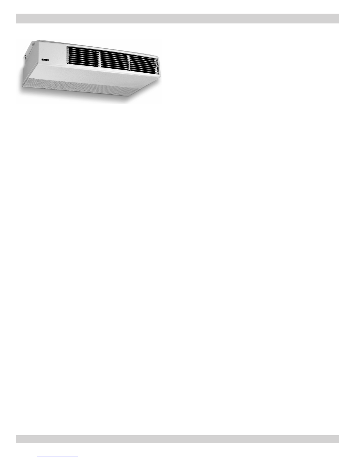
CEILING-SUSPENDED AIR HANDLER CCP
Description
• CCP is highly effective ceiling-suspended air handler for
applications where fully exposed or partially recessed
cabinetry can be used.
• Partially recessed mounting, units easily adapt to
standard T-bar, drop-ceiling openings.
• CCP is designed for residential and commercial
applications where unit may be concealed in softs or
other structural spaces with only intake and discharge
grilles exposed. When concealing unit make provisions
to soft for future access to unit for maintenance
purposes.
• When offering Infra-Red Control option, due to infrared receiver location on the unit, CCP model cannot be
mounted in soft or another structural space.
• Aluminum supply air louvers are dual adjustable for
air ow direction, to provide air ow throws to suit
any installation. Louvers are mounted in high impact
polystyrene front section.
• CCP incorporates dual blowers that produce efcient,
quiet operation, suitable for both residential and
commercial applications.
Optional Controls & Components
Common Section for complete list of Optional Controls/Components
See page 4 in
Mounting Preparation
Choose best location for unit. Use cardboard template
(provided with unit packing) to “test t” unit before
installation
1.
CCP Series is designed to be mounted to horizontal
surface which should be plumb and level.
2.
Using template, mark a spot where piping should
penetrate wall.
3.
Determine appropriate hole size and cut through
mounting surface.
Piping for new construction can be roughed in before
wallboard or panels are put in place. PVC pipe may be used
as pipe chase.
Mounting
4.
Remove access panel, attach front panel and louvers to
chassis section with supplied nuts.
5.
Front panel shipped separately in cartoning.
6.
Secure unit to ceiling using appropriate hardware
(screws for wood, anchors for masonry).
7.
CCP unit can be ceiling suspended using threaded rods
and double nuts to ensure fasteners won’t loosen.
8.
Pitch unit slightly towards drain for proper condensate
removal
.
• CCP units offer wide range of options, including
supplemental electric or hydronic heat options, factory
or eld installed condensate pump, and optional digital
and hand held IR remote controls.
• Hanger brackets and fresh air openings are standard on all
models.
• Optional trim kits are available for surface mounting
applications.
• If equipped with hydronic heat, CCP will only operate as
single-stage heating unit and not as two-stage heating unit.
Fresh Air
• 4” round knockout accepts 4” round duct.
• Dampers, wall collars, and outdoor grilles are eld
supplied. Do not allow moisture or other foreign
matter to enter through fresh air intake.
• When ducting, pitch slightly to outside to prevent
moisture from entering the chassis.
8
 Loading...