

Page 1

Audio Technologies Inc. 856-719-9900 sales@atiaudio.com www.
audio.com
Product Description
The ATI UADC-1 Utility Analog-Digital Converter / Switch provides professional quality 24-bit A-to-D
conversion, along with AES audio path insertion and interruption functions. The UADC-1 may be used as a
standalone high quality A/D converter or to insert stereo analog inputs into an AES stream via remote control,
making it a perfect companion for analog EAS encoders/decoders.
The UADC-1 is equipped for failsafe operation with relay bypass in case power is lost. The A/D converter is
shipped to provide broadcast standard 44.1 kHz sample rates, with 32 kHz or 48 kHz sampling selectable via
internal jumpers. XLR analog audio inputs are balanced when shipped from the factory, but may be switched
to unbalanced, single ended inputs via internal jumpers. (See INSTALLATION Section for internal jumper
settings.)
The front panel includes left and right analog input trimmers, Audio Present and Clipping LEDs for each
analog input, and status LEDs to indicate Remote Active, Analog or Digital Input Selected and Power.
The rear panel includes XLR connectors for balanced left and right analog audio inputs, AES input and AES
output. 3-pin connectors are provided for Unbalanced analog stereo input and remote control inputs. Power is
supplied via a 110 VAC outboard power supply (included), which supplies 24 VDC to the unit.
Installation
Please examine your UADC-1 Utility Analog-Digital Converter / Switch carefully for any damage that may have
occurred during shipping. If damage is noted, please notify the shipper immediately and retain the packaging
for inspection. The package contains the UADC-1 unit, one 24 VDC / 600 mA power supply and this manual.
Please read this manual thoroughly before you install and operate the unit. Do not use this product in any
application where a life threatening condition could result due to its failure.
Use care when installing the UADC-1 in high RF environments. Shielded cable is suggested for all audio
connections. All shields should be tied to the “G” or ground connector pins. It is recommended that all cables
connected to the UADC-1 be looped through ferrite cores to suppress RF. Power line surge protection with RF
filtering is also suggested for the external power supply.
To gain access to the UADC-1 unit’s internal configuration jumpers, disconnect power and remove the six
Philips screws that secure the cover. When configuration is completed, reinstall the cover with the six screws
and re-connect the power.
The ATI UADC-1 Utility Analog-Digital Converter / Switch can be rack mounted using the optional 21075-501
19” Rack Mount Shelf Assembly and 21098-501 ½ RU Filler Panel.
UADC-1
Utility Analog-Digital Converter / Switch
Installation and Set-up Manual
Page 2
Audio Technologies Inc. 856-719-9900 sales@atiaudio.com www.
audio.com
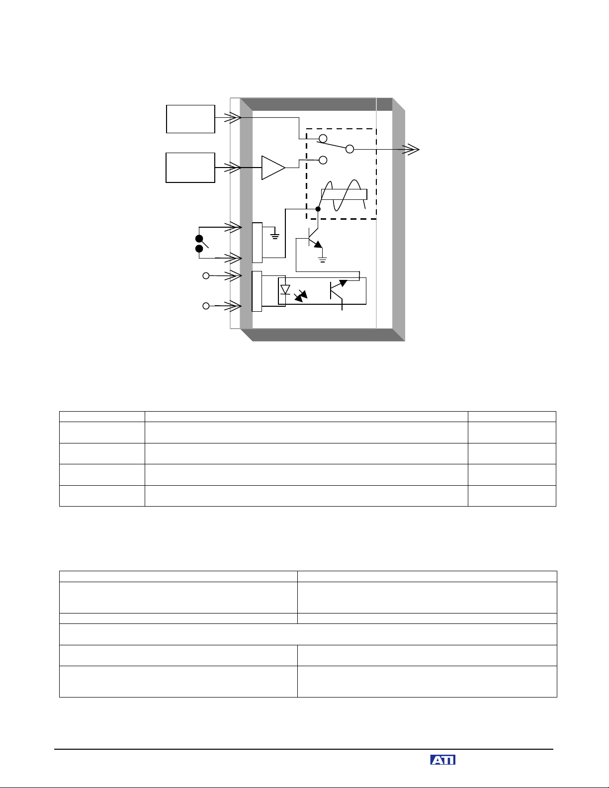
FUNCTIONAL BLOCK DIAGRAM:
INTERNAL CONFIGURATION JUMPERS:
Refer to the following table to change the XLR analog inputs from balanced to unbalanced, and to change the
default 44.1kHz sampling rate to either 32kHz or 48kHz:
FUNCTION
JUMPER SETTING
COMMENTS
XLR Input
Termination
Jumper JM1 grounds the Left XLR inverting input. Jumper JM2 grounds the
right XLR inverting input.
Factory Default:
JM1 and JM2 open
32 kHz Sample
Rate
Jumpers JM3, JM4 and JM5 should be in the 32 position. Jumpers JM6 and
JM7 should be in the 32/48 position.
44.1 kHz Sample
Rate
Jumpers JM3, JM4 and JM5 should be in the 44/48 position. Jumpers JM6
and JM7 should be in the 44 position.
Factory Default
Setting
48 kHz Sample
Rate
Jumpers JM3, JM4 and JM5 should be in the 44/48 position. Jumpers JM6
and JM7 should be in the 32/48 position.
REAR PANEL CONNECTIONS:
Refer to the following table when making rear panel connections to your UADC-1:
AUDIO CONNECTION
DESCRIPTION & COMMENTS
Left & Right XLR Analog Inputs
XLR connectors are Hi-Z, active balanced as supplied from
factory, but can be unbalanced with internal jumper setting
(see above).
Un-Balanced Stereo Analog Input
Via Euroblock connector; connect shield to G terminal.
Connect your source equipment to the appropriate left and right analog inputs. For monaural sources, tie the left and right
inputs together. Be sure to observe correct phasing.
AES XLR Input
For main AES Source input. When used as an EAS insert
switcher, this would normally be the feed from your air chain.
AES XLR Output
This output will provide either the AES audio input or the A-toD converted signal from the left and right analog inputs. The
selected input is indicated on the front panel.
Remote Control A
Remote Control B
AES
Output
AES Digital
Audio
Source
Analog
Audio
Source
ADC
+5VDC
+5 to 24VDC
A1
A2
A3
NC
+5VDC
Opto
B1
B2
B3
Page 3

Audio Technologies Inc. 856-719-9900 sales@atiaudio.com www.
audio.com
REMOTE CONTROL INPUT CONFIGURATION:
Audio input switching can be actuated either via external contact closure or by external positive voltage from 5
to 24VDC. Refer to the following table for wiring instructions:
CONNECTOR & FUNCTION
DESCRIPTION & COMMENTS
Connector A
Dry, for use with external switch or relay
AES input is selected with pins A1 and A3 open. To
select analog inputs short pins A1 and A3. Pin A2 is
unused.
Connector B
Wet, for use with +5 to +24VDC input
AES input is selected when no voltage is present on pin
B1. To select analog inputs, supply a positive DC voltage
between 5 and 24 volts to pin B1. Pin B3 should be
connected to remote ground. Pin B2 is unused.
FRONT PANEL CONTROLS AND INDICATORS:
Power
Confirms the presence of 24VDC from the external power supply
Analog Input Present
Left and Right Present LEDs begin to illuminate at an input level of -28dBm.
LEDs are fully illuminated when level reaches -24dBm.
Analog Input Clipping
Left and Right Clipping LEDs begin to illuminate with +18dBm input. LEDs
are fully illuminated at +20dBm.
Analog Input Gain
With a nominal +4dBm analog input, adjust these controls to set the desired
AES output level when the Analog Input is selected via remote control
Remote Active
Indicates that the remote control input on the rear panel has selected the
Analog Input. Analog Input LED will also be illuminated.
Digital Input
Indicates that the remote control input on the rear panel has selected the
Digital Input
SPECIFICATIONS:
Analog Input Level
-10dBu to +24dBu
+4dBu analog input provides –20dBfs AES output
Analog Input Impedance
10kΩ balanced
Frequency Response
10 – 20kHz, +/-0.5dB
Distortion
< .02% THD / IMD
Noise
< -90dB EIN
AES Output Impedance
110Ω, balanced from analog / A-D input. Passive when AES input is active.
Power Requirements
24VDC, 600mA, wall transformer, supplied
Size and Weight
1/2 rack space; 5.0 lbs. shipping weight
Options
21075-501 Rack Mounting Shelf; 21098-501 1/2 RU Blank Panel, WA100-2
220 VAC 50-60Hz CE-approved External Power Supply
Page 4

Audio Technologies Inc. 856-719-9900 sales@atiaudio.com www.
audio.com
ATI - Limited 1-Year Warranty
ATI warrants this product to be free from defects in materials and workmanship to its original owner for a period
of one year from date of purchase. ATI will repair or replace such product or part thereof that upon inspection
by ATI, is found to be defective in materials or workmanship.
The Proper Return Authorization Number must be obtained from ATI in advance of return. Contact ATI at
sales@atiaudio.com or 856.719.9900 to receive an RA Number and shipping information.
A written statement setting forth the name, address, and daytime telephone number of the original owner,
together with receipt from the original purchase, and a brief description of any claimed defects, must
accompany all returns. Parts or product for which replacement is made shall become the property of ATI.
The customer shall be responsible for all costs of transportation and insurance, both to and from the factory of
ATI, and may be required to prepay such costs.
ATI shall use reasonable efforts to repair or replace any product covered by this limited warranty within thirty
days of receipt. In the event repair or replacement shall require more than thirty days, ATI shall notify the
customer accordingly. ATI reserves the right to replace any product that has been discontinued from its product
line with a new product of comparable value and function.
This warranty shall be void in the event a covered product has been damaged, or failure is caused by or
attributable to acts of God, abuse, accident, misuse, improper or abnormal usage, failure to follow instructions,
improper installation or maintenance, alteration, or lightning, power fluctuations and other incidental or
environmental conditions. Further, product malfunction or deterioration due to normal wear is not covered by
this warranty.
ATI DISCLAIMS ANY WARRANTIES, EXPRESS OR IMPLIED, WHETHER OF MERCHANTABILITY OF
FITNESS FOR A PARTICULAR USE, EXCEPT AS EXPRESSLY SET FORTH HEREIN. THE SOLE
OBLIGATION OF ATI UNDER THIS LIMITED WARRANTY SHALL BE TO REPAIR OR REPLACE THE
COVERED PRODUCT, IN ACCORDANCE WITH THE TERMS SET FORTH HEREIN. ATI EXPRESSLY
DISCLAIMS ANY LOST PROFITS, GENERAL, SPECIAL, INDIRECT OR CONSEQUENTIAL DAMAGES
WHICH MAY RESULT FROM BREACH OF ANY WARRANTY, OR ARISING OUT OF THE USE OR
INABILITY TO USE ANY ATI PRODUCT.
Some states do not allow the exclusion or limitation of incidental or consequential damages or limitation on how
long an implied warranty lasts, so the above limitations and exclusions may not apply to you.
This warranty gives you specific legal rights, and you may also have other rights that vary from state to state.
ATI reserves the right to modify or discontinue, without prior notice to you, any model or style product.
Please register your UADC-1 on our website www.ATIAudio.com. This will allow us to keep
you informed of updates and related product information.
 Loading...