

Page 1
MCDA-208
Ultra-Low-Jitter Studio Master Clock
Dual 1x4 AES/EBU Distribution Amplifier
OPERATING AND MAINTENANCE MANUAL
© Copyright 2011, DaySequerra Corp.
Day Sequerra ! 154 Cooper Rd. #902 ! W. Berlin, NJ 08091 ! Voice 856-719-9900 ! sales@daysequerra.com ! www.atiaudio.com
Page 2

2
!
"#$%&'()!"*+,*-!
!"#$%&of&'()*%)*+&
&
,"-%*.&/)-(01"*2()&
3&
4)5"672)8&
3&
/)+*"$$"*2()&9(6"*2()&
3&
:0(;)<2)8&
3&
=$%6*0(1"8)%*26&'"5"#2$2*.&
3&
>"2)*%)")6%&
3&
?%6$"0"*2()+&(-&'()-(012*.&
3&
@20&!%15%0"*;0%&A&B;12<2*.&
C&
D;)6*2()"$&,*")<"0<+&
C&
?%+6025*2()&
C&
/)5;*+&
E&
F;*5;*+&
E&
G(H%0&
E&
D0()*&G")%$&?2+5$".&A&,H2*6I%+&
J&
K%"0&G")%$&'())%6*2()+&A&,H2*6I%+&
L&
'()-28;0"*2()&?/G&,H2*6I%+&
M&
N$(67&?2"80"1&
OP&
/)+*"$$"*2()&
OO&
,5%62-26"*2()+&
OQ&
R"00")*.&
O3&
&
%--!./0123!.434.546!$*7849,4..*!#:.;<!#:;7./012!'(==<!
%--!-:0:3!*+6!2.*64>*.?!,346!14.4/+!*.4!214!;.:;4.27!:@!214/.!.43;4A2/54!:B+4.3<!
8;4A/@/A*2/:+3!3,CD4A2!2:!A1*+04<!!
>'?@SQPMT&K%U2+2()&@V&
MCDA-208 FEATURES
• Accepts AES3, S/PDIF, AES11, and Word Clock inputs
• Independent Dual 1X4 AES/EBU Clock Distribution Amplifiers
• Generates standard sample rates of 44.1, 48, 88.2, 96, 176.4 or 192 kHz
• Displays input sample rates of 32, 44.1, 48, 88.2, 96, 176.4 and 192 kHz
• Divide-Down ultra-low jitter clock with exceptional stability
• Full diagnostics for all inputs and operating conditions
• Loop-thru inputs for AES External Sync and Word Clock
• Switchable input termination for all inputs
• 8 independently driven 75-ohm BNC Word Clock outputs; 6 isolated AES/EBU 110
Ohm XLR outputs
• Flexible signal routing system
• Automatic and manual external sync and internal sync generator functions
• Switchable Input Re-clocking on all Clock inputs
• Automatic Input Equalization for long input lines
• Front panel control locking system
Page 3

3
!
"#$%&'()!"*+,*-!
SAFETY INFORMATION
To reduce risk of electric shock, do not remove covers. There are no user-serviceable items
inside. Please refer servicing to qualified personnel.
UNPACKING
Examine all shipping cartons for external damage and retain all damaged cartons for inspection
by the carrier. Examine all equipment for any sign of damage. Do not connect AC mains power
to a unit, which appears to be damaged. Contact the carrier to file a damage claim.
INSTALLATION LOCATION
This equipment must be installed in a location meeting the environmental conditions specified
below. Adequate cooling must be provided if units are to be operated in high temperature
locations. Exposure to liquid and condensation must be avoided.
GROUNDING
This equipment is connected to earth through the center conductor of the AC mains cable.
Proper grounding protects operators from electric shock, and it must be maintained whenever
the unit is connected to AC.
ELECTROMAGNETIC COMPATIBILITY
This unit complies with electromagnetic requirements described in EMC Directive 2004/108/EC
and FCC Part 15. This unit does not generate undue electromagnetic interference, and is
adequately protected against electromagnetic interference so that it can operate properly.
MAINTENANCE
This unit requires no maintenance other than periodic wiping with a soft dry cloth to remove any
dust or contaminating substances. Do not use solvents for cleaning.
DECLARATIONS OF CONFORMITY
Class A Equipment – FCC Notice
This equipment has been tested and found to comply with the limits for a Class A digital device,
pursuant to FCC CFR 47, Part 15.
CE Declaration of Conformity
ATI Audio Inc., West Berlin, New Jersey 08091 USA, declares that all Model MCDA-208/ units
are in conformity with the following EU regulations and amendments:
Low Voltage Directive (LVD) 2006/95/EC (replaces 73/23/EEC)
Electromagnetic Compatibility (EMC): EMC Directive 2004/108/EC
EMC: EN55103-1/-2:2009, electromagnetic environments E2.
Safety: EN 60950:2006
Page 4

4
!
"#$%&'()!"*+,*-!
NOTE: This equipment has been tested and found to comply with the limits for a Class A digital
device, pursuant to part 15 of the FCC Rules. These limits are designed to provide reasonable
protection against harmful interference when the equipment is operated in a commercial
environment. This equipment generates, uses, and can radiate radio frequency energy and, if
not installed and used in accordance with the instruction manual, may cause harmful
interference to radio communications. Operation of this equipment in a residential area is likely
to cause harmful interference in which case the user will be required to correct the interference
at his own expense.
West Berlin, NJ USA, 31 July 2009
President
AIR TEMPERATURE AND HUMIDITY
Normal operation of this unit is warranted while operating in a temperature range of +5 to
+40°C, with relative humidity ranging from 5 to 85%. Care should be taken to avoid operation
outside these limits or erratic operation may result.
FUNCTIONAL STANDARDS
All Model MCDA-208 units are in conformity with the following industry standards:
AES3-2003, AES11-2003 and IEC958 SPDIF
DESCRIPTION
The ATI Model MCDA-208 contains an ultra-low jitter studio master clock generator, dual 1X4
AES/EBU Digital Audio Distribution. Operation of the unit is simple and straightforward, and it is
housed in a rugged 2U rack mount enclosure. All audio connections are made directly to the
unit’s built-in BNC connectors, and no special breakout cables or accessory jack panels are
required.
When used as a studio master clock, the MCDA can generate an exceptionally stable 44.1, 48,
88.2, 96, 176.4 or 192 kHz clock reference for the purpose of synchronizing all of your
connected digital equipment. This single clock source assures a trouble-free digital workflow
throughout your digital facility. The output clock format can be either Word Clock or Super Word
Clock, and this signal is available on all eight of the MCDA’s individually driven BNC outputs.
The Clock Generator output can also be routed to either or both Clock output groups.
If you prefer to use another source for your reference clock, the MCDA can function as a 2X8
Clock Distribution Amplifier. It can accept an AES3 audio signal or an AES Word Clock as an
input, and will output either Word Clock or Super Word Clock from its eight BNC output
connectors. These reference clock signals can also be routed to either or both Clock output
groups as word clock.
The Clock Generator section provides automatic switchover, as well as dual redundant back-up
control. Failure of an external clock will cause the Clock Generator to automatically generate its
own preprogrammed reference signal. Internal clock can also be selected manually. The
MCDA’s dual redundant back-up control allows one MCDA unit to be designated as a master
while a second MCDA serves as the slave; it’s clock source then becomes active when the
master clock’s clock is not active.
Page 5

5
!
"#$%&'()!"*+,*-!
Since the purity of the clock reference is critical to the quality of the finished audio product, ATI
has taken steps to assure that the MCDA generates the lowest jitter clock reference available.
The MCDA’s internal reference is derived from a 24 MHz precision oscillator and divided down
to achieve an ultra-stable signal, rather than multiplying up from a base reference as in some
other units.
The MCDA’s Clock Distribution Amplifier has both Input and Loop-thru outputs to allow
downstream equipment to be fed from the input reference signal. When no downstream
equipment is connected, the inputs should be terminated via the front panel Input Termination
switch.
When fed from an external reference signal, the MCDA will indicate the clock frequency of the
input signal from 32 through 192 kHz. The full diagnostics front panel will also indicate Word
Length, Digital Errors if any, and whether the digital stream is Pro or Consumer mode. These
diagnostic indicators are switchable to display these details for either Clock input, or for the AES
External Sync In or Word Clock input.
The MCDA can also derive a Frame Clock (Word Clock) from the Clock signal input to Clock 1.
This Frame Clock signal is available for routing to all BNC outputs.
Clock 1, AES SYNC IN, and WORD CLOCK IN will lock to AES3, AES11 or Word Clock. AES
SYNC IN, and WORD CLOCK IN generate “Word Clocks” to be outputted.
Alarm LEDs located on the left side of the front panel indicates loss of carrier occurring on any
input, regardless of the position of the Source Monitor selector.
A front panel lock switch protects all settings. The MCDA retains all of its settings, even if power
is removed.
INPUTS
Incoming Clock formatted digital audio data, AES11 or Word Clock is applied to individual
input transformers. Input termination resistors at 75 ohms for BNC inputs can be switched
in or out of the circuit with the front panel Input Term switch. Inputs should always be
terminated unless they are looped through to another device or a second MCDA input.
OUTPUTS
The MCDA has eight balanced, transformer driven XLR outputs arranged in groups of four;
i.e., 1 through 4 and 5 through 8. It also has eight isolated BNC outputs which function as a
single group. Rear panel mounted DIP switches allow you to configure the MCDA to send
the following signals to any or all of these three groups of outputs:
1. CLOCK INPUT 1
2. CLOCK INPUT 2
3. AES SYNC-IN Clock derived Word Clock
4. WORD CLOCK INPUT External Word Clock
5. Internal Clock Generator
6. Clock 1 derived Frame Clock
It is not necessary to terminate unused outputs, as each is individually isolated.
POWER
Connector for socket fused IEC 320/C13. Power cord is supplied. The MCDA has a rear panel
On Off power switch.
Page 6

6
!
"#$%&'()!"*+,*-!
POWER INPUT SPECIFICATIONS:
Voltage .......................................................................................85 ~ 264Vac
Frequency .....................................................................................47 to 63Hz
Page 7

7
!
"#$%&'()!"*+,*-!
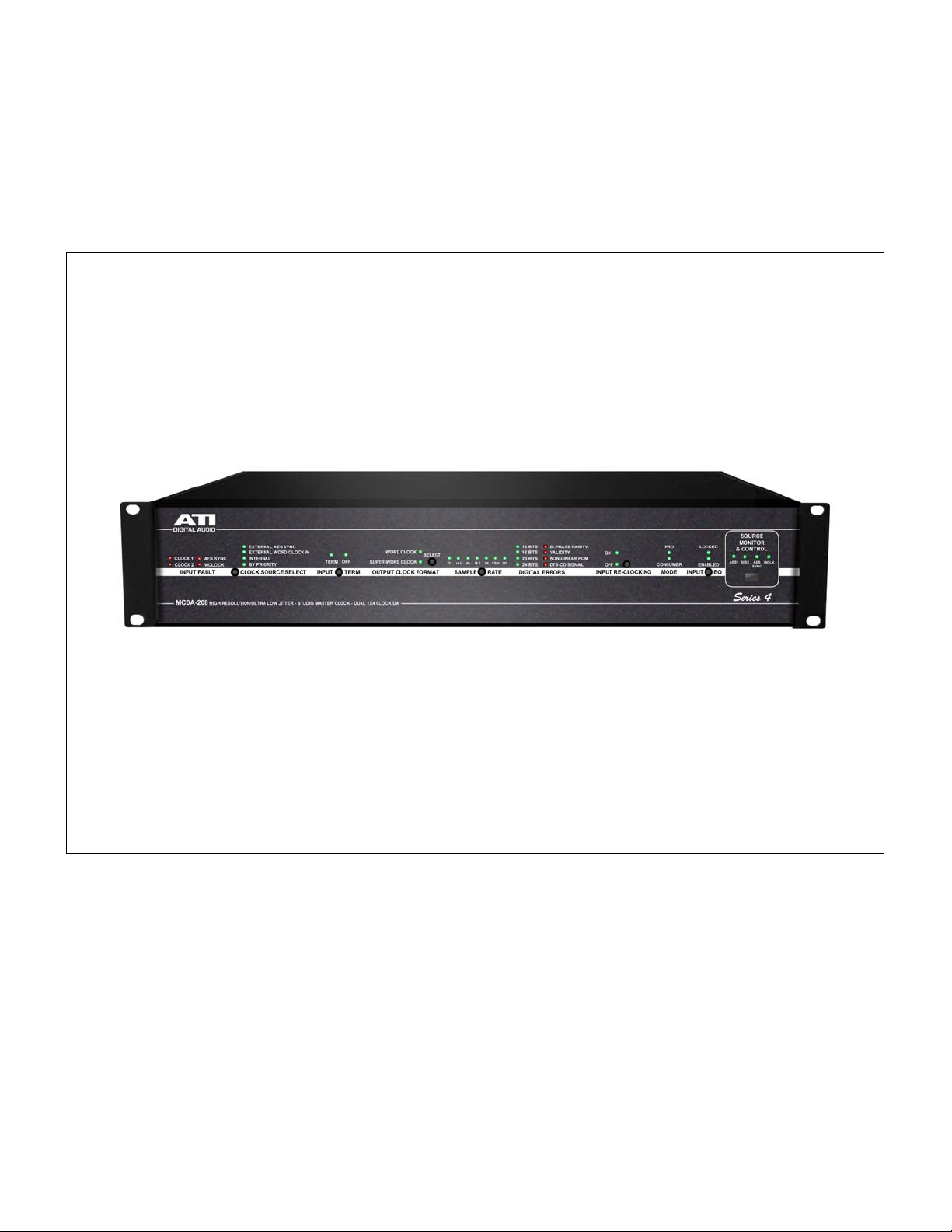
FRONT PANEL DISPLAYS AND SWITCHES
POWER
Indicates that the MCDA is powered and power switch is on.
INPUT FAULT
Indicates loss of carrier on any of the four inputs, INPUT 1 (CLOCK 1), INPUT 2 (CLOCK 2),
AES SYNC-IN (AES SYNC) or WORD CLOCK INPUT (WCLK).
CLOCK SOURCE SELECT
Selects timing reference source for clock generator. Sequentially pressing the Clock Source
Select button selects from External AES Sync (AES SYNC-IN), External Word Clock Input
(WORD CLOCK INPUT), or Internal crystal reference. An additional button press illuminates the
BY PRIORITY LED and enables automatic priority selection of timing reference source in the
order: AES External Sync, External Word Clock In, or Internal. Selection is enabled only when
Source Monitor & Control WCLK LED is on.
INPUT TERM
Indicates whether the input termination is on or off for the source selected by the Source
Monitor & Control switch. Press the INPUT TERM button to toggle the setting. Settings are
individual for each source selected, and are memorized and retained through power outages.
OUTPUT CLOCK FORMAT
Indicates either Word Clock or Super Word Clock format available at outputs. Press the
SELECT button to toggle the setting. Enabled only when WCLK LED is on.
SAMPLE RATE
When Clock Source Select switch is set to INTERNAL and the WCLK LED is on, the SAMPLE
RATE switch selects the internal generator sample rate. For manual Word Clock sample rate
selection, set Source Monitor & Control to WCLK LED on. When the Clock Source switch is set
to EXTERNAL AES SYNC or EXTERNAL WORD CLOCK IN, the LEDs indicate the sample rate
of the external input from 32 kHz through 192 kHz.
WORD LENGTH
Indicates the Word Length of the input signal from 16 through 24 bit.
DIGITAL ERRORS
Indicates four error conditions encountered in digital signals as an aid to troubleshooting: BiPhase/Parity, Validity, Non-Linear PCM and DTS-CD Signal.
Page 8

8
!
"#$%&'()!"*+,*-!
INPUT RE-CLOCKING
Indicates Input Re-Clocking is On or Off. Press the RE-CLOCKING button to toggle the setting.
Note that this function applies only to the AES/EBU inputs and does not affect the AES External
Sync and Word Clock inputs. Settings are individual for either INPUT 1 (AES 1) or INPUT 2
(AES 2). , and are memorized and retained through power outages.
MODE
Indicates whether incoming AES/EBU input signal is Pro or Consumer mode.
INPUT EQ
Enables automatic input equalization for long input cables. LOCKED indicates input data is
present and acceptable. ENABLED indicates equalization is applied. Press the INPUT EQ
button to enable automatic equalization. Settings are memorized and retained through power
outages. Jitter may be reduced even more when used in conjunction with re-clocking.
SOURCE MONITOR & CONTROL
Selects the input source to be monitored and/or controlled; either INPUT 1 (AES 1), INPUT 2
(AES 2), AES SYNC-IN (AES SYNC) or WORD CLOCK INPUT (WCLK). Internal Generator
settings are made when WCLK selected. To monitor an input signal, use Source Monitor Select
to determine error details by selecting particular input.
FRONT PANEL LOCK
The Front Panel Lock protects your front panel settings. Press and hold the FRONT PANEL
LOCK button to lock all the front panel controls. Press and hold again to unlock.
REAR PANEL CONNECTIONS AND SWITCHES
!
!
!
Clock INPUT 1
Provides a balanced, transformer isolated 110 ohm AES/EBU input that may be routed to BNC
Outputs 1 through 4 or 5 through 8 via the configuration DIP switches. A Frame Clock (Word
Clock) is derived from this input, which may be routed to any or all output groups.
Clock INPUT 2
Provides a balanced, transformer isolated 110 ohm AES/EBU input that may be routed to BNC
Outputs 1 through 4 or 5 through 8 via the configuration DIP switches.
Page 9

9
!
"#$%&'()!"*+,*-!
AES SYNC IN
Provides a balanced, transformer isolated 110 ohm AES Sync input that a derived Word Clock
may be routed to XLR Outputs 1 through 4, Outputs 5 through 8 or BNC Outputs 1 through 6 via
the configuration DIP switches. A Frame Clock is derived from this input. When present, this
signal provides first priority for synchronizing the internal Clock Generator when CLOCK
SOURCE SET is set to BY PRIORITY.
AES LOOP-THRU
Provides a convenient loop-thru port for the AES External Sync input. When looping this signal
to another device, set Input Termination to Off.
WORD CLOCK INPUT
Provides an isolated high impedance or 75 ohm Word Clock input to synchronize the internal
Clock Generator. It may be routed to XLR Outputs 1 through 4, Outputs 5 through 8 and/or BNC
Outputs 1 through 6 via the configuration DIP switches. When present, this signal provides the
second priority for synchronizing the internal Clock Generator when CLOCK SOURCE SET is
set to BY PRIORITY.
WORD CLOCK LOOP-THRU
Provides a convenient loop-thru port for the Word Clock input. When looping this signal to
another device, set Input Termination to Off.
CONFIGURATION DIP SWITCHES
Provides routing and other selections for signal flow in the unit. See the DIP Switch Routing
Table for settings:
The switches are labeled left to right BANK A switch “1” is “DIP Switch 1 in the following tables.
DIP Switches 7 through 12 have no function in the MCDA-208/DA106. In this view Outputs 1-4
are connected to input 1. OUTPUT 5 to 8 are connected to Word Clock generated by the
WORD CLOCK INPUT. The WCLK OUT 1 through 6 are connected the internal clock
generator.
Page 10

10
!
"#$%&'()!"*+,*-!
SOURCE SELECTION FOR AES/EBU OUTPUTS 1, 2, 3 & 4
Selected
Source "
AES/EBU
INPUT 1
AES/EBU
INPUT 2
EXT AES
SYNC
INPUT
WORD
CLOCK
INPUT
AES 1
FRAME
CLOCK
DIP
Switch 1
Down
Up
Down
Up Up
DIP
Switch 2
Down
Down
Down
Down
Up
DIP
Switch 3
Down
Down
Up
Up Up
SOURCE SELECTION FOR AES/EBU OUTPUTS 5, 6,7 & 8
Selected
Source "
AES/EBU
INPUT 1
AES/EBU
INPUT 2
EXT AES
SYNC
INPUT
WORD
CLOCK
INPUT
AES 1
FRAME
CLOCK
DIP
Switch 4
Down
Up
Down
Up Up
DIP
Switch 5
Down
Down
Down
Down
Up
DIP
Switch 6
Down
Down
Up
Up Up
SOURCE SELECTION FOR WORD CLOCK OUTPUTS
Selected
Source "
AES/EBU
INPUT 1
AES/EBU
INPUT 2
EXT AES
SYNC
INPUT
WORD
CLOCK
INPUT
INT
CLOCK
GEN
Note 1
AES 1
FRAME
CLOCK
DIP
Switch 13
Down
Up
Down
Up
Down
Up
DIP
Switch 14
Down
Down
Down
Down
Up
Up
DIP
Switch 15
Down
Down
Up
Up
Up
Up
Notes:
1. For “BY PRIORITY CLOCK”, DIP switch 13 through 15 must be set to this group of
positions to permit use of the internal clock generator and the automatic priority function,
as configured by the front panel switches.
Page 11

11
!
"#$%&'()!"*+,*-!
MCDA-208 BLOCK DIAGRAM
Input processing includes transformer isolation, cable termination, cable equalization, and AES
digital audio interface receiver (DIR) and digital audio interface transmission (DIT). The output
of each input signal processor is routed to a multiplexing chip which allows connection to each
of the three output groups. Selection is controlled by the position of the configuration switches
on the back panel of the MCDA. Each output port is driven by its own driver preventing
interaction between outputs. Two separate highly accurate crystal clock sources allow the
MCDA to achieve frame rates accurate to less than 1 part per million. A microprocessor sets up
the MCDA for operation.
Super Word Clock is a bit clock like signal that is exactly 256 times the frequency of the
associated frame rate for sample rates up to 96 k samples per second or 128 times for rates
above 96 k samples.
Page 12

12
!
"#$%&'()!"*+,*-!
INSTALLATION
LOCATION
The MCDA is readily installed into a 2 RU, 19” rack. The MCDA is only to be installed in an
inside location where it is protected from inclement weather. Operate the MCDA in temperature
range of +5 to +40°C (105°F), with relative humidity ranging from 5 to 85%.
POWER
Connector for socket fused IEC 320/C13. Power cord is supplied. The MCDA has a rear panel
On Off power switch.
POWER INPUT SPECIFICATIONS:
Voltage .......................................................................................85 ~ 264Vac
Frequency .....................................................................................47 to 63Hz
This equipment is connected to earth through the center conductor of the AC mains cable.
Proper grounding protects user/operators from electric shock, and it must be maintained
whenever the unit is connected to AC.
WIRING
BNC connectors use 75-ohm coax (RG59). Select a cable for losses less than 20dB at 12MHz
(for data rates up to 96 k samples) at the maximum distance you require. Keep cable length as
short as possible, especially when working with Super Word clock rates.
Page 13

13
!
"#$%&'()!"*+,*-!
MCDA-208/ SPECIFICATIONS
INPUTS
CONNECTORS
XLR female for AES/EBU and AES External Sync BNC for Clock
and Word Clock
LEVEL
XLR 200mVp-p minimum; BNC 1 Vp-p
IMPEDANCE
Transformer isolated, balanced and floating, XLR 110!, BNC 75 !;
input terminations may be switched in or out via front panel control
CLOCK
Locked, filtered and reconstructed from external input signals with
exceptionally stable PLLs less than 800ps jitter.
SYNC FREQUENCY
30 to 200 kHz
OUTPUTS
AES/EBU OUT CONNECTORS
6 x XLR
LEVEL
5 Vp-p loaded at 110!
IMPEDANCE
110!
JITTER
< 800 picoseconds
CLOCK OUT CONNECTORS
6 x BNC
LEVEL
2 Vp-p loaded with 75!
IMPEDANCE
75!, unbalanced
LOOP-THRU
XLR-M and BNC
INTERNALLY GENERATED
WORD CLOCK
Sample rate accuracy of ±1 ppm
INDICATORS
INPUT FAULT
Clock 1, Clock 2, AES External Sync and Word Clock
CLOCK SOURCE SELECT
AES External Sync, External Word Clock In, Internal, By Priority
INPUT TERMINATION
Terminated or Off
OUTPUT CLOCK FORMAT
Word Clock or Super-Word Clock
SAMPLE RATE
32, 44.1, 48. 88.2, 96, 176.4 or 192 kHz
WORD LENGTH
16 Bits, 18 Bits, 20 Bits and 24 Bits
DIGITAL ERRORS
Bi-Phase Parity, Validity, Non-Linear PCM and DTS-CD Signal
INPUT RE-CLOCKING
On and Off
MODE
Pro and Consumer
INPUT EQ
Locked and Enabled
SOURCE MONITOR &
CONTROL
Clock 1, Clock 2, AES External Sync, Word Clock
POWER
Internal Supply, 115/230VAC ±10%, 50/60Hz, 10VA, IEC320 3 pin
connector
SIZE
2 RU Package, 19” (48.3cm) W x 3.5“ (8.9cm) H x 8.5” (21.6cm) D
WEIGHT
9 pounds (4.1 kg) net; 10 pounds (4.5 kg) shipping weight
WARRANTY
Limited, One Year Warranty
8;4A/@/A*2/:+3!*.4!3,CD4A2!2:!A1*+04!B/21:,2!+:2/A4!2:!,;0.*64!214!;4.@:.>*+A4!:@!:,.!;.:6,A23<!
Page 14

14
!
"#$%&'()!"*+,*-!
One Year Limited Warranty
DaySequerra warrants ATI products to be free from defects in materials and workmanship to its original
owner for one (1) year from the date of purchase. DaySequerra will repair or replace such product or part
thereof that upon inspection by DaySequerra, is found to be defective in materials or workmanship
subject to conditions contained herein.
ATI products are sold worldwide, through a network of authorized ATI dealers and distributors. This
Warranty is for the sole benefit of the original purchaser of an ATI product, purchased directly from an
authorized ATI dealer or distributor, is restricted to such original purchaser, and shall not be transferred to
a subsequent purchaser of the product. Proof of purchase in the form of a bill of sale or receipted invoice
substantiating that the product was purchased directly from an authorized ATI dealer or distributor and is
within the warranty period must be presented to obtain warranty service. Removal or alteration of the
original ATI serial number from a product automatically renders that product warranty null and void.
A Return Authorization Number must be obtained from DaySequerra in advance of return. Parts or
product for which replacement is made shall become the property of DaySequerra. The customer shall be
responsible for all costs of transportation and insurance to and from the DaySequerra factory, and all
such costs will be prepaid.
DaySequerra shall use reasonable efforts to repair or replace any product covered by this limited
warranty within thirty days of receipt. In the event repair or replacement shall require more than thirty
days, DaySequerra shall notify the customer accordingly. DaySequerra reserves the right to replace any
product that has been discontinued from its product line with a new product of comparable value and
function.
This warranty shall be void in the event a covered product has been damaged, or failure is caused by or
attributable to acts of God, abuse, accident, misuse, improper or abnormal usage, failure to follow
instructions, improper installation or maintenance, alteration, or lightning, power fluctuations and other
incidental or environmental conditions. Further, product malfunction or deterioration due to normal wear
is not covered by this warranty.
DAYSEQUERRA DISCLAIMS ANY WARRANTIES, EXPRESSED OR IMPLIED, WHETHER OF
MERCHANTABILITY OR FITNESS FOR A PARTICULAR USE, EXCEPT AS EXPRESSLY SET
FORTH HEREIN. THE SOLE OBLIGATION OF DAY SEQUERRA UNDER THIS LIMITED WARRANTY
SHALL BE TO REPAIR OR REPLACE THE COVERED PRODUCT, IN ACCORDANCE WITH THE
TERMS SET FORTH HEREIN. DAYSEQUERRA EXPRESSLY DISCLAIMS ANY LOST PROFITS,
GENERAL, SPECIAL, INDIRECT OR CONSEQUENTIAL DAMAGES WHICH MAY RESULT FROM
BREACH OF ANY WARRANTY, OR ARISING OUT OF THE USE OR INABILITY TO USE ANY
DAYSEQUERRA PRODUCT.
Some states do not allow the exclusion or limitation of incidental or consequential damages or limitation
on how long an implied warranty lasts, so the above limitations and exclusions may not apply to you.
This warranty gives you specific legal rights, and you may also have other rights that vary from state to
state. DaySequerra reserves the right to modify or discontinue, without prior notice to you, any model or
style product. If warranty problems arise, or if you need assistance in using your product contact:
DaySequerra
154 Cooper Road, Building 902
West Berlin, NJ 08091
Page 15

15
!
"#$%&'()!"*+,*-!
For more information, please call 856-719-9900, visit www.atiaudio.com or email us at
support@daysequerra.com
.!
Day Sequerra ! 154 Cooper Rd. #902 ! W. Berlin, NJ 08091 ! Voice 856-719-9900 ! sales@daysequerra.com ! www.atiaudio.com
 Loading...