

Page 1
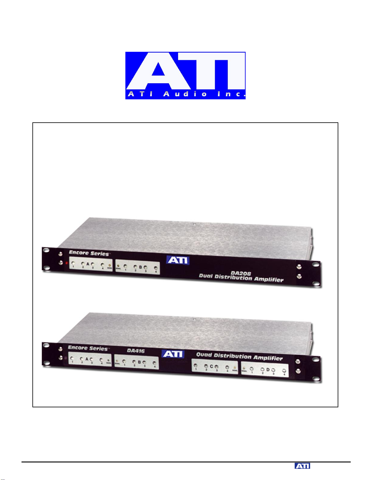
DA208 & DA416
DISTRIBUTION AMPLIFIERS
OPERATING AND MAINTENANCE MANUAL
© Copyright 2011, ATI Audio Inc.
ATI Audio Inc. ■ Tel: 856-719-9900 ■ Fax: 856-504-0220 ■ sales@daysequerra.com ■ www. audio.com
Page 2

DESCRIPTION
Your DA208 or DA416 provides two (DA208) or four (DA416) independent one-in by
four-out circuit groups. A four-output feed is sufficient for many applications; however,
if you need more outputs, you can parallel channels by bridging several inputs across the
same line for 1X8, 2X8 or 1X16 operation. Since each input circuit has 30k ohms
balanced input impedance, you can simply terminate your source line with a single 620
ohm resistor (if necessary) and then parallel as many inputs as necessary across it.
Each input can bridge line levels up to +24dBm without clipping. Common mode hum
signals are attenuated by 70dB and the input resistor network is split and heavily
bypassed for good protection from RF signals riding on the input lines. The input
differential amplifier operates at slightly less than unity gain to optimize input headroom
and to prevent any signal clipping from occurring prior to the gain controls.
Each output consists of an adjustable gain stage driving the HI output terminal along with
a unity gain inverter stage. The inverter drives the LO output in opposite phase to provide
an active balanced output. The adjustable gain stage utilizes a unique circuit arrangement
that allows us to provide a smooth, full range logarithmic gain control for each output
using a linear cermet potentiometer. This circuit provides 20dB gain at full clockwise
rotation, unity gain in the 12 o'clock position and tapers smoothly to full off at the full
CCW position. Since we actually vary the gain of the output stage rather than taking the
more conventional approach of adjusting the input level to a fixed gain stage, you can use
the DA at low output levels with very little noise penalty. You can easily match the DA
outputs to console medium level inputs (-20dBm) or drive semi-pro RCA inputs (single
ended at .10Vrms) without requiring outboard attenuator pads.
Each balanced output stage is isolated from the output terminals by DC blocking
capacitors and 400 ohms of build-out resistance. The build-out resistors are split and
bypassed to prevent any RF signals that might be picked up on an output line from
feeding back into the DA.
Your DA has clipping indicators to warn you of overdriven and overloaded outputs.
These indicators individually sense nonlinear operation of any output channel by
measuring the error voltage at the feedback terminal of the HI side output amplifier. As
long as the output stage operates linearly, the error voltage at its negative input (for
example WA pin 9) will remain very small. The onset of clipping, current limiting or
even slew rate limiting immediately causes a large increase in this error signal, which is
then fed through R25 to the error amplifier U5A at pin 13. U5A, in turn, drives the
clipping LED through Q1. Feedback voltages also feed the error amplifier from three
other output channels. To avoid any crosstalk through the summing network, CR3 across
R13 prevents nonlinear clipping of U5A and therefore maintains an extremely small
common point voltage at U5A pin 13. If any single output or any combinations of outputs
are driven too high, they will light the clipping LED. Each clipping indicator monitors
only four outputs, making it easy to locate the "hot" output.
ATI Audio Inc. ■ Tel: 856-719-9900 ■ Fax: 856-504-0220 ■ sales@daysequerra.com ■ www audio.com
Page 3

Your DA operates from a bipolar 15VDC regulated supply. The power supply is designed
for minimum susceptibility to power line transients and conducted RFI using ferrite
beads, double capacitive bypasses and a non-concentric wound semi-toroidal power
transformer.
INSTALLATION
MOUNTING
Your ENCORE SERIES DA is designed for rack mounting on standard E.I.A. 1-3/4 inch
centers. Each unit dissipates approximately 10 watts and is ventilated through slots in the
rear panel.
WIRING
There are three wire grounded plugs. The power line ground could cause a loop with your
studio ground. If you are sure your studio ground will provide adequate protection to
personnel in case of an AC line short to chassis, a 3-to-2 AC adapter can be used to
isolate the power line ground. We recommend that the adapter be removed and the power
line ground be reconnected prior to any service work requiring removal of the studio
ground from the chassis.
To allow maximum flexibility in grounding in high RF environments, the DA circuit
grounds are isolated from case ground. For normal operation, add a ground jumper from
any Phoenix connector ground terminal to the chassis ground screw.
The four inch silver bearing low inductance copper strap which you are, of course, using
for your studio ground is not going to fit around the #6 chassis ground screw on the
amplifier rear panel. Run the strap to within a few inches of the chassis and jump to the
chassis ground screw with shield braid.
We have taken serious measures to keep RF out of your DA. This includes split and
bypassed input and output resistor networks, beaded, bypassed and isolated power inputs,
non-concentric wound power transformers and double ground plane PC boards.
However, in a difficult broadcast application, any RF shielding and suppression system is
going to be no better than the ground system into which it is trying to dump the unwanted
RF. For optimal product performance, be sure to have a good facility grounding system.
Audio inputs and outputs should be connected using the rear panel labels as a guide. HI
outputs are all in phase with each other and in phase with the HI inputs.
ATI Audio Inc. ■ Tel: 856-719-9900 ■ Fax: 856-504-0220 ■ sales@daysequerra.com ■ www. audio.com
Page 4

CAUTION
Your Distribution Amplifier has active drivers for both HI and LO output terminals. DO
NOT GROUND either HI or LO terminals. If you are driving a single-ended
(unbalanced, one side grounded) high impedance or 600 ohm load, it should be connected
between either HI to GND or LO to GND. If you are driving a balanced load, connect it
between HI and LO output terminals. It is generally unnecessary to terminate the DA
with a 600 ohm load if it is driving a high impedance input, although placing a
terminating resistor across a hi-Z input at the receiving end will occasionally reduce RF
pickup.
ADJUSTMENTS
It is sometimes difficult to maintain good noise performance when using a DA to drive
medium level console (-20dBm) or IHF (.1V) equipment inputs. You may have found it
necessary in the past to insert attenuator networks between a DA and medium level
console inputs to allow the DA to operate at a high enough output level to maintain a
good signal-to-noise ratio. Your DA will reduce its already low output noise still further
as you turn down its gain. In the absence of high RF fields, you can distribute input
signals as low as -20dBm to multiple loads at 0 to -20dBm levels.
MAINTENANCE
Power supply voltages are + and - 15VDC nominal.
IC output DC Voltages under no signal, shorted input conditions should remain within
.1V of ground. Greater deviation is an indication of IC or circuit problems.
MODIFICATIONS
230 VAC OPERATIONS
Your DA is wired for 115 VAC, 50/6OHz operation unless otherwise requested at the
time ordering. It can be modified for 230 VAC operations by removing the power
transformer primary jumpers J3 and J5 and inserting a jumper in J4. Units supplied with a
-230VAC suffix have had this wiring change made at the factory.
Different types of attachment plug or line cords may be required for connection to
alternate supply voltages.
ATI Audio Inc. ■ Tel: 856-719-9900 ■ Fax: 856-504-0220 ■ sales@daysequerra.com ■ www. audio.com
Page 5

DA208 and DA416 SPECIFICATIONS
OUTPUT LEVEL: +24dBm into 600 ohm balanced loads
THD: .001% typical, 20Hz to 20kHz
IMD: .05% maximum, SMPTE measurement
SLEW RATE: 13 Volts per microsecond
RESPONSE: +/-. 25dB, 30Hz to 20kHz
NOISE: -100dBm EIN 20Hz to 20kHz
GAIN: 20dB maximum; each output has 40dB smooth adjustment
range going to full off
CROSSTALK: 70dB minimum at 1kHz
OUTPUT IMPEDANCE: 400 ohms balanced, 200 ohms single-ended, split and RF
bypassed, AC coupled
INPUTS: 30K ohm active balanced, split and RF bypassed; +22dBm
maximum input level
HUM REJECTION: 70dB CMR at 60Hz
POWER: 115/230 VAC +10%, 47-63Hz, 12 VA
SIZE: 19" (48.3cm) W x 1-3/4" (4.4cm) H x 7-1/2" (19.1cm) D
SHIPPING WEIGHT 5 pounds (2.3kg)
TERMINALS: Euro style modular connectors
ATI Audio Inc. ■ Tel: 856-719-9900 ■ Fax: 856-504-0220 ■ sales@daysequerra.com ■ www. audio.com
Page 6

One Year Limited Warranty
ATI warrants this product to be free from defects in materials and workmanship to its original
owner for a period of one year from date of purchase. ATI will repair or replace such product or
part thereof, which upon inspection by ATI, is found to be defective in materials or workmanship.
The Proper Return Authorization Number must be obtained from ATI in advance of return.
Contact ATI at 856-626-3480 or email sales@atiaudio.com to receive the number and
instructions for return of your unit.
A written statement providing the name, address, daytime telephone number and email address
of the original owner, together with receipt from the original purchase, and a brief description of
any claimed defects, must accompany all returns. Parts or product for which replacement is made
shall become the property of ATI.
The customer shall be responsible for costs of transportation and insurance to the factory of ATI,
and shall be required to prepay such costs.
ATI shall use reasonable efforts to repair or replace any product covered by this limited warranty
within thirty days of receipt. In the event repair or replacement shall require more than thirty days,
ATI shall notify the customer accordingly. ATI reserves the right to replace any product that has
been discontinued from its product line with a new product of comparable value and function.
This warranty shall be void in the event a covered product has been damaged, or failure is
caused by or attributable to acts of God, abuse, accident, misuse, improper or abnormal usage,
failure to follow instructions, improper installation or maintenance, alteration, or lightning, power
fluctuations and other incidental or environmental conditions. Further, product malfunction or
deterioration due to normal wear is not covered by this warranty.
ATI DISCLAIMS ANY WARRANTIES, EXPRESS OR IMPLIED, WHETHER OF
MERCHANTABILITY OF FITNESS FOR A PARTICULAR USE, EXCEPT AS EXPRESSLY SET
FORTH HEREIN. THE SOLE OBLIGATION OF ATI UNDER THIS LIMITED WARRANTY SHALL
BE TO REPAIR OR REPLACE THE COVERED PRODUCT, IN ACCORDANCE WITH THE
TERMS SET FORTH HEREIN. ATI EXPRESSLY DISCLAIMS ANY LOST PROFITS, GENERAL,
SPECIAL, INDIRECT OR CONSEQUENTIAL DAMAGES WHICH MAY RESULT FROM
BREACH OF ANY WARRANTY, OR ARISING OUT OF THE USE OR INABILITY TO USE ANY
ATI PRODUCT.
Some states do not allow the exclusion or limitation of incidental or consequential damages or
limitation on how long an implied warranty lasts, so the above limitations and exclusions may not
apply to you.
This warranty gives you specific legal rights, and you may also have other rights that vary from
state to state.
ATI reserves the right to modify or discontinue, without prior notice to you, any model or style
product.
If warranty problems arise, or if you need assistance in using your product contact us.
ATI Audio Inc. ■ Tel: 856-719-9900 ■ Fax: 856-504-0220 ■ sales@daysequerra.com ■ www. audio.com
 Loading...