

Page 1

ALL-IN-WONDER® X800
Series
Installation and Setup
User’s Guide
P/N 137-70847-10
ATI
Page 2

ii
Copyright © 2004, ATI Technologies Inc. All rights reserved.
ATI and ATI product and product feature names are trademarks an d/or registered trademarks of ATI
Technologies Inc. All other company and/or product names are trademarks and/or registered
trademarks of their respective owners. Features, performance and spec ifications are s ubject to change
without notice. Product may not be exactly as shown in diagrams.
Reproduction of this manual, or parts thereof, in any form, without the expre ss written permission of ATI
Technologies Inc. is strictly prohibited.
Disclaimer
While every precaution has been taken in the preparation of this document, ATI Technologies Inc.
assumes no liability with respect to the operation or use of ATI hardware, software or other products
and documentation described herein, for any act or omission of ATI concerning such products or this
documentation, for any interruption of service, loss or interruption of business, loss of anticipatory
profits, or for punitive, incidental or consequential damages in connection with the furnishing,
performance, or use of the ATI hardware, software, or other products and documentation provided
herein.
ATI Technologies Inc. reserves the right to make changes without further notice to a product or system
described herein to improve reliability, funct io n or design. With respect to ATI products which this
document relates, ATI disclaims all express or implied warranties regarding such products, including
but not limited to, the implied warranties of merchantability, fitness for a particular purpose, and noninfringement.
Product Notices
Dolby* Laboratories, Inc.
Manufactured under license from Dolby Laboratories. Confidential Unpublished Works.
© 1992-1997 Dolby Laboratories, Inc. All rights reserved.
Macrovision
Apparatus Claims of U.S. Patent Nos. 4,631,603, 4,577,216, 4,819,098, and 4,907,093 licensed for
limited viewing uses only.
This product incorporates copyright protection tec hno logy tha t is protected by method claims of certain
U.S. patents and other intellectual property rights owned by Macrovision Corporation and other rights
owners. Use of this copyright protection technology must be authorized by Macrovision Corporation,
and is intended for home and other limited viewing uses only unless otherwise authorized by
Macrovision Corporation. Reverse engineering or disassembly is prohibited.
Documentation Updates
ATI is constantly improving its product and associated documentation. To maximize the value of your
ATI product, you should ensure that you have the latest documentation. ATI’s documentation contains
helpful installation/configuration tips and other valuable feature information.
Page 3

IMPORTANT SAFETY INSTRUCTIONS
L
• Read Instructions - All the safety and operating instructions should
be read before the product is operated.
• Retain Instructions - The safety and operating instructions should
be retained for future reference.
• Heed Warnings - All warnings on the product and the operating
instructions should be adhered to.
• Compatibility - This option card is for use only with IBM AT or
compatible UL Listed personal computers that have Installation
Instructions detailing user installation of card cage accessories.
• Grounding - For continued protection against risk of electric shock
and fire, this accessory should be installed only in products equipped
with a three-wire grounding plug, a plug having a third (grounding)
pin. This plug will only fit into a grounding-type power outlet. This is a
safety feature. If you are unable to insert the plug into the outlet,
contact your electrician to replace the obsolete outlet. Do not defeat
the safety purpose of the grounding-type plug.
• Secure Attachment
tightened as to provide continuous bonding between the option card
and the PC chassis.
• Outdoor Antenna Grounding - Since an outdoor antenna or cable
system is connected to the product, be sure that the antenna or cable
system is grounded so as to provide some protection against voltage
surges and built-up static charges. Article 810 of the National
Electrical Code, ANSI/NFPA 70, provides information with regard to
proper grounding of the mast and supporting structure, grounding of
the lead-in wire to the antenna discharge unit, size of grounding
conductors, location of antenna-discharge unit, connection of
grounding electrodes, and requirements for the grounding electrode.
• Lightning - For added protection for this product during a lightning
storm, or when it is left unattended and unused for long periods of
time, unplug it from the wall outlet, and disconnect the antenna or
cable system. This will prevent damage to the product due to
lightning and power-line surges.
• Power Lines - An outside antenna system should not be located in
the vicinity of overhead power lines or other light or power circuits, or
where it can fall into such power lines or circuits.
• Antenna Installation - When installing an outside antenna system,
extreme care should be taken to keep from touching such power lines
or circuits, as contact with them may be fatal.
• Note to CATV System Installer - This reminder is provided to call
the CATV systems installer’s attention to Section 820-40 of the NEC,
which provides guidelines for proper grounding and, in particular,
specifies that the cable ground shall be connected to the grounding
system of the building, as close to the point of cable entry as
practical.
- All card securement pins shall be completely
iii
Page 4

iv
Page 5

Contents
Getting Started. . . . . . . . . . . . . . . . . . . . . . . . . . . . . 1
System Requirements 2
Before You Begin 2
Record Your Serial and Part Numbers 2
Update Your AGP Chipset Drivers 3
Uninstall Previous Graphics Card Drivers 4
Available Resources . . . . . . . . . . . . . . . . . . . . . . . . 5
Using the Digital User’s Guide 5
Getting Additional Accessories 5
Product Registration 5
Customer Care 6
Warranty Information 7
Hardware Warranty Service Statement 7
Warranty Service 7
Limitations 8
Compliance Information 9
FCC Compliance Information 9
Industry Canada Compliance Statement 9
CE Compliance Information 10
L’Information de conformité de la CE 11
CE-befolgungInformationen 11
v
Installing Hardware . . . . . . . . . . . . . . . . . . . . . . . . 13
Quick Installation 13
Detailed Installation 14
Installing the Card 15
Connecting Display Devices 16
Turning on the System 16
Input and Output Adapters 17
To watch movies on your PC
or record video from your VCR or camcorder 17
To display your PC output on TV
and record PC output on videotape 19
To display your PC output on a high-definition TV 21
Compatibility with earlier
ALL-IN-WONDER® products 23
Page 6

vi
Installing Software. . . . . . . . . . . . . . . . . . . . . . . . . 25
Installing Drivers and Software in Windows® 25
Software Installation Prerequisites 25
HYDRAVISION™ Multi-monitor Management 26
Monitor Configuration 27
Reinstalling Drivers 27
Starting the ATI Multimedia Center 28
ATI’s CATALYST™ Software Suite . . . . . . . . . . . 29
Introduction 29
Features 29
Multiple Displays and 3D Gaming 29
HYDRAVISION™ 29
Accessing the CATALYST™ Software Suite 29
ATI Displays Tab 30
Dynamic Display Reassignment 32
ATI Color Tab 33
Hotkeys 37
Color Hotkeys Settings 38
ATI Options Tab 40
ATI Rotation Tab 42
Rotation HotKeys 44
ATI Overlay Tab 44
Video Overlay 44
Clone Mode Settings 46
ATI 3D Tab 47
Custom Properties Dialog 50
Direct 3D® Compatibility Settings 53
OpenGL® Compatibility Settings 54
ATI VPU Recover Tab 55
Using TV Display and Capture Features . . . . . . . 57
Using TV Out 57
Viewing Your PC’s Display on a TV 57
Connecting to a TV or VCR 57
Starting Windows® with TV Display Enabled 58
Using and Adjusting TV Display Features 58
TV Display Hardware Restrictions 58
Using a Monitor vs. Using TV Display 58
Adjusting Monitor Display 59
Viewing Text on a TV 59
Reducing Edge Distortion 59
Using TV Display Alone 60
Page 7

Using Games and Applications 60
Using SCART Connectors for European Televisions 61
Using Multiple Displays . . . . . . . . . . . . . . . . . . . . 63
Connecting Your Monitors 63
Display Configurations 65
MULTVIEW™ 67
MULTVIEW™ audio requirements 68
EAZYLOOK™ 68
Troubleshooting . . . . . . . . . . . . . . . . . . . . . . . . . . 69
Uninstalling Old Graphics Card Software 69
Windows® New Hardware Found 69
Installing the CATALYST™ Software Suite 70
Solution Selector 71
Index 77
vii
Page 8

viii
Page 9

CHAPTER 1:
Getting St arted
Welcome to the convergence of your PC, TV and video! This new
technology changes the way you view TV, graphics, and video on your PC.
The ALL-IN-WONDER® family of cards are powerful TV tuners, DVD
players, Personal Video Recorders, and 2D & 3D graphics and video
accelerators. Their features will take your PC’s graphics and video
capabilities to the next level.
TV-ON-DEMAND™ and TV Listings enhance your television experience.
Using an attached video camera, the ALL-IN-WONDER® family provides
time-lapse video recording and motion-triggered video recording, which
can be used for security applications. Your card’s advanced video
recording and editing features also give you Video CD and DVD authoring
capability.
You can use your ALL-IN-WONDER® to connect your computer to a
television. This feature is ideal for playing games, giving presentations,
watching movies, and browsing the Internet. (For more information, see
Viewing Your PC’s Display on a TV on page 57.)
1
ALL-IN-WONDER® also turns your PC into an intelligent TV with the
following features:
TV-ON-DEMAND™ THRUVIEW™
MULTVIEW™ TV MAGAZINE
EAZYLOOK™ Zoom and Pan
Scheduled Viewing Channel Scanning
Video Recording Closed Captioning with
HOTWORDS™
Program Transcript Recording
(North America only)
Personal Video Recorder with RealTime Video Compression
AC-3 Digital Audio Playback
supporting Dolby® 5.1 surround
sound
Interactive Program Guide (in
selected countries)
REMOTE WONDER™ USB RF
Remote Control (optional)
Page 10
2 System Requirements
System Requirements
Hardware • Intel® Pentium® 4; AMD Athlon® or compatible.
• 128 MB of system memory; 256 MB or more for best
performance.
• Motherboard with free AGP 8X/4X slot and correct
AGP chipset-driver.
• CD-ROM drive (for installation software).
• 300 watt or greater power supply recommended. (A
350 watt power supply may be required in some fully
loaded PC systems.)
Operating
System
Monitor • High-resolution MultiSync or multi-frequency monitors
• Windows® XP Service Pack 1 and Service Pack 2.
• Windows® XP
• Windows® 2000 with Service Pack 1 (or later).
or any other type of VGA monitor.
• Digital flat-panel (DFP) displays or digital CRT display.
Before You Begin
Before you begin installing your ALL-IN-WONDER® X800 Series
product, please do the following.
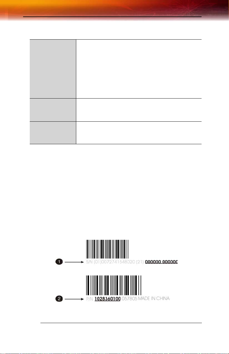
Record Your Serial and Part Numbers
The serial number and 102 part number printed on the graphics card are
required for registration. They are located on a sticker on the back of the
card.
X
Serial number (S/N)
Page 11

Record Your Serial and Part Numbers 3
Y
Write these numbers down before installing your new ATI product.
102 part number (P/N)
Update Your AGP Chipset Drivers
Your new ATI ALL-IN-WONDER® X800 Series card uses the AGP bus,
and so it requires not only display drivers, but also drivers that enable AGP
functionality for the motherboard chipset.
To ensure a successful installation of your new ATI graphics card, you
must make sure that you have installed the latest AGP chipset drivers
before replacing your current graphics card.
How to determine the motherboard chipset on your system
1 Open the Control Panel from the Start Menu and select System; in
Windows® XP’s Category View, System can be found under
Performance and Maintenance.
2 In the System Properties dialog, select the Hardware tab.
3 Select Device Manager.
4 From the Device Manager tree view, expand the System Devices
branch.
5 Scroll through the list of system devices until you find a listing for the
AGP controller.
These drivers may be referred to using any of the following names:
• AGP Driver
• AGP Miniport
• AGP VXD Driver
• Chipset Driver
• GART Driver
• VGART
Often you will see the name of a motherboard chipset in connection
with these terms. For example:
• ALi GART Driver
• AMD AGP Miniport
• Intel VGART
• VIA AGP Driver
The chipset manufacturer’s name will appear as part of the device
name.
Page 12

4 Record Your Serial and Part Numbers
Once you have determined the chipset manufacturer for your motherboard,
obtain and then install the latest AGP drivers from that manufacturer’s Web
site.
WARNING - Installing the wrong AGP chipset drivers may prevent
you from successfully launching Windows®. Make sure that the
drivers you install are designed to function correctly with your
L
motherboard. If you are uncertain, please consult with your
motherboard manufacturer for advice.
For your convenience, here is a list of common motherboard
manufacturers:
VIA Technologies
Acer Laboratories (ALI)
Silicon Integrated Systems
(SIS)
Advanced Micro Devices (AMD)
Intel Technologies
General Motherboard/chipset
information
www.viaarena.com
www.ali.com.tw
www.sis.com
www.amd.com
support.intel.com
www.motherboards.org
Uninstall Previous Graphics Card Drivers
To ensure the successful installation of your new ALL-IN-WONDER®
X800 Series card, you must uninstall the drivers for the existing graphics
card before removing it from your computer.
To uninstall previous drivers
With your current graphics card still in your computer:
1 Close all applications that are currently running.
2 Navigate to the Control Panel and select Add/Remove Programs.
3 Select your current graphics card drivers and select Add/Remove.
The wizard will help you remove your current display drivers.
Note: If the previously installed graphics card has any additional
software installed, it should also be removed at this point.
4 Restart your system after the drivers have been removed.
Page 13

Using the Digital User’s Guide 5
A vailable Resources
This chapter tells you where to find your user’s guide, where to get
additional accessories, how to register your product, and warranty and
compliance information.
Using the Digital User’s Guide
Your ATI graphics card comes complete with a User’s Guide in Portable
Document Format (PDF). The User’s Guide describes in detail the features
and functions of your ATI graphics card and the associated software. You
will need Adobe® Reader® software, available from www.adobe.com.
To open the User’s Guide
1 Insert the ATI Installation CD-ROM into your CD-ROM drive.
2 If Windows® runs the CD-ROM automatically, proceed to step 6.
3 Click Start > Run.
4 Type the following: D:\ATISETUP
(If D is not your CD-ROM drive, substitute the correct drive letter.)
5 Click OK.
6 Click Documentation.
7 Click User Guides.
Getting Additional Accessories
Additional and replacement cables, installation CD-ROMs, manuals, and
other accessories for ATI products can be purchased from the online ATI
store at ati.com/online/accessories.
Product Registration
To receive Customer Service you must register your product with ATI
within 30 days of purchase. An Online Product Warranty Registration form
is available at:
ati.com/online/registration
Page 14

6 Customer Care
Customer Care
For detailed instructions on how to use your ATI product, refer to the
Online User’s Guide included on your ATI installation CD-ROM.
If you require further assistance with your product, the following Customer
Care options are available:
Service Availability Access Cost
Online 24/7 ati.com/online/customercare. Complimentary
T elephone US &
Canada
T elephone US &
Canada Priority
Service
T elephone US &
Canada Priority
Pay-PerIncident
Europe and
Other Regions
Mail ATI TECHNOLOGIES
9:00am-7:00PM EST.
Monday to Friday.
9:00am-7:00PM EST.
Monday to Friday.
9:00am-7:00PM EST.
Monday to Friday.
10:30am - 7:00 PM GMT
Monday to Friday.
1-905-882-2626 Complimentary to
1-900-733-2841 $1.25 perminute
1-877-284-7379 $19.95 per incident
+49-1803-347345 Complimentary to
INC.
Attention: Customer
Care
1 Commerce Valley
Drive East
Markham, Ontario
Canada L3T 7X6
registered users.
Toll charges may
apply.
(subject to change
without notice).
(subject to change
without notice).
registered users else
US$19.95 per incident
(subject to change
without notice).
Toll charges to
Germany may apply.
Complimentary
Page 15

Warranty Information 7
ATI Customer Care will work to resolve your issue and help you to get your
ATI product up and running. If your issue is not resolved, our technicians
will determine whether the difficulty you are experiencing is the result of
the ATI product, whether your product contains a defect, and whether your
product is under warranty.
• ATI Customer Care is unable to assist with refunds, returns, or
exchange specific inquiries. If resolving the problem being
experienced is critical to your decision to keep the product, it is your
responsibility to ensure that you know and are within the period of
time your reseller will allow for refunds, returns or exchange.
• ATI is not responsible for any expense incurred accessing Customer
Care. It is expected that customers will review the expense
associated with the available support options and will choose the
method that best meets their needs and budget.
• ATI Customer Care reserves the right to limit support options for
products that are not registered or are at End of Life.
Warranty Information
Hardware Warranty Service Statement
ATI Technologies Inc. warrants to the original purchase r of the hardwa re t hat the product is in good
working condition, according to its specifications at t he time of shipment, for a period of three years from
the date of original purchase.
Should the product, in ATI’s opinion, malfunction within the warranty period, ATI will, at its discretion,
repair or replace the product upon receipt with an equivalent. Any replaced parts be come t he property
of ATI. This warranty does not apply to the software component of the installati on, usage not in
accordance with product specifications and instructions, natural or personal disaster, or unauthorized
alterations, repairs, or modifications.
Proof of purchase may be required, if doubt exists regarding warranty eligibility. Late model products are
assumed to be under warranty. ATI accepts ordinals, photocopies and faxes as proof of purchase when
required
Warranty Service
For warranty service instructions visit :
ati.com/online/warranty or contact one of our Customer Service Representatives using one of the
aforementioned means.
• Before shipping any unit for repair, obtain an RMA number for warranty service.
• When shipping your product, pack it securely, show the RMA and serial number of the product
on the outside, and ship prepaid and insured.
• ATI will not be held liable for damage or loss to the product in shipment.
• Standard warranty service consists of repair upon receipt.
• ATI reserves the right to replace the product with a serviced product at their sole discretion at
any time.
Page 16

8 Warranty Information
• You are responsible for the cost of shipping the product to ATI. ATI plays the cost of returning
the product to you.
Products which are repaired under warranty are guaranteed for the remainder of the original warranty
period. Repairing or exchanging a product does n ot start a new warranty period. If, at the time of repair,
a product is already “out of warranty” or within the last 90 days of the warranty period , ATI will guarantee
the repair for the full 90 days. All other terms and conditions of the original warranty apply.
Limitations
• This warranty is valid only if the online Product Warranty Registration form at:
ati.com/online/registration
is successfully submitted within 30 days of purchase of said product.
• All warranties for this product, expressed or implied, will expire three (3) years* from date of
original purchase.
•
*The REMOTE WONDER™ unit is warranted for 1 year.
The HDTVCOMPONENT ADAPTER is warranted for 1 year.
All accompanying cables and accessories are warranted for 90 days.
• No warranties for this product, expressed or implied, shall extend to any pers on who purchases
the product in a used condition.
• The liability of ATI in respect of any defective product will be limited to t he repair or replacement
of such product. ATI may use new or equivalent-to-new replacement parts. Defective product
will be sent in for repair or replacement only. ATI makes no other representations or warranties
as to fitness for a particular purpose, merchantability or otherwise in respe ct of the p roduct . No
other representations, warranties or conditions, shall be implied by statute or otherwise. In no
event shall ATI be responsible or liable for any damages, including but not limit ed to the loss of
revenue or profit, arising:
• From the use of the product, as a result of any event, circumstance, action or abuse beyond the
control of ATI; whether such damages be direct, indirect, consequential, special or otherwise
and whether such damages are incurred by the person to whom this warranty extends or a th ird
party
• From the loss of use of the product, as a result of any event, circumstance, action or abuse
beyond the control of ATI; whether such damages be direct, indirect, consequential, special or
otherwise and whether such damages are incurred by the person to whom this warrant y extends
or a third party.
• Unauthorized repairs to an ATI board level product will void the warranty offered by ATI
Technologies. ATI reserves the rightto refuse to service any product which has been altered,
modified, or repaired by non-ATI service presonnel.
Page 17

Compliance Information 9
Compliance Information
FCC Compliance Information
This ALL-IN-WONDER® product complies with FCC Rules part 15. Operation is
subject to the following two conditions
• This device may not cause harmful interference, and
• This device must accept any interference received, including interference that
may cause undesired operation.
This equipment has been tested and found to comply with t he limits for a Class B digital device, pursuant
to Part 15 of the FCC Rules. These limits are designed to provide reasonable protec tion against harmful
interference in a residential installation. This equipment generates, uses and can radiate radio frequency
energy and, if not installed and used in acc ordance with manufacturer's instructions, may ca use harmful
interference to radio communications. However, there is no guarantee tha t interference will not occur in
a particular installation. If this equipment does cause harmful interference to radio or television
reception, which can be determined by turning the equipment off and on, the user is encouraged to try
to correct the interference by one or more of the following measures:
• Re-orient or relocate the receiving antenna.
• Increase the separation between the equipment and receiver.
• Connect the equipment to an outlet on a circuit different from that to which the receiver is
connected.
• Consult the dealer or an experienced radio/TV technician for help.
The use of shielded cables for connection of the monitor to the graphics card is
required to ensure compliance with FCC regulations. Changes or modifications to
this unit not expressly approved by the party responsible for compliance could
void the user's authority to operate this equipment.
Industry Canada Compliance Statement
ICES-003 This Class B digital apparatus complies with Canadian ICES-003.
Cet appareil numérique de la Classe B est conforme à la norme NMB-003 du Canada.
For further compliance information:
ATI Research Inc.
4 Mount Royal Ave.
Marlborough, MA
01752-1976
USA
508-303-3900
Page 18

10 Compliance Information
CE Compliance Information
EMC Directive 89/336/EEC and amendments 91/263/EEC, 92/31/EEC and 93/68/ EEC, Class B Digital
Device
EN 55022:1998/CISPR 22 Class B, Limits and Methods of Measurement of Radio Interference
Characteristics Information Technology Equipment.
EN 55024:1998, Immunity of Information Technology Equipment (ITE), including
EN 61000-4-2, EN 61000-4-3, EN 61000-4-4, EN 61000-4-5,
EN 61000-4-6, EN 61000-4-11
EN 60950:92 + A1:93 + A2:93 +A3:95 + A4:97
Directive EMC 89/336/CEE et amendements 91/263/CEE, 92/31/CEE et 93/68/CEE, dispositif
numérique de Classe B
EN 55022:1998/CISPR 22 Classe B, Limites et méthodes de mesure des caractéristiques
d'interférences radiophoniques, Matériel des technologies de l'info rmation.
EN 55024:1998, Norme sur l'immunité de matériel des technologies de l'information, et comprenant
EN 61000-4-2, EN 61000-4-3, EN 61000-4-4, EN 61000-4-5,
EN 61000-4-6, EN 61000-4-11
EN 60950:92 + A1:93 + A2:93 +A3:95 + A4:97
EMC Richtlinie 89/336/EEC und Änderungen 91/263 /EEC, 92/ 31/EEC un d 93 /6 8/E EC, Digit ales Gerät
der Klasse B
EN 55022:1998/CISPR 22 Klasse B, Beschränkungen und Verfahren der Messung von
informationstechnischen Ausrüstungen mit Funkstörmerkmalen
EN 55024:1998, Unempfindlichkeits-Standard für informationstechnische Ausrüs tungen, einschliesslich
EN 61000-4-2, EN 61000-4-3, EN 61000-4-4, EN 61000-4-5,
EN 61000-4-6, EN 61000-4-11
EN 60950:92 + A1:93 + A2:93 +A3:95 + A4:97
EMC Directive 89/336/EEC and Amendments 92/31/EEC and 93/68/EEC, for Class B Digital Device.
EN 55022:1998/CISPR 22:1997, - Class B - Limits and Methods of Measurement of Radio Dist urbance
Characteristics of Information Technology Equipment.
EN55024:1998/CISPR 22:1997, - Information Techno logy Equipment - Immunity Characteristics - Limits
and Methods of Measurement.
Low Voltage Directive for TV-Tuner-Equipped products
73/23/EEC - The Low Voltage Directive.
EN 60950: 1992+A1+A2+A3+A4 - Safety of Information Technology Equipment.
Page 19

Compliance Information 11
L’Information de conformité de la CE
Directive EMC 89/336/CEE et amendement 92/31/CEE et 93/68 /EEC, dispositif numérique de Class e B.
EN 55022:1998/CISPR 22:1997, - Class B - Limites et méthodes de mesure des caractéristiques
d'interférences radiophoniques, Matériel des technologies de l'info rmation.
EN 55024:1998/CISPR 24:1997, Limites et méthodes de mesure des caractéristiques d'immunité,
Matériel des technologies de l'information Equipement de Technologie de l'Information Caractéristiques d'Immunité - Limites et méthodes de mesure.
Directive de Basse Tension pour produits contenir tuner de télévision
73/23/CEE - Directive basse tension.
EN 60950 : 1992+A1+A2+A3+A4 - Sécurité du matériel des technologies de l'information.
CE-befolgungInformationen
EMC Richtlinie 89/336/EEC und Änderungen 92/31/EEC und 93/ 68/EEC, Digitales Gerät der Klas se B.
EN 55022:1998/CISPR 22:1997, - Klasse B - Grenzwerte und Meßverfahren für Funkstörungen von
Einrichtungen der Informationstechnik.
EN 55024:1998/CISPR 24:1997, Einrichtungen der Informationstechnik, Störfestigkeitseigenschaften,
Grenzwerte und Prüfverfahren.
Niederspannung Richtlinie für Produkte Enthalten Fernsehen tuner
73/23/EEC - Niederspannungsrichtlinie.
EN 60950: 1992+A1+A2+A3+A4 - Sicherheit für Einrichtungen der Informationstechnik.
Page 20

12 Compliance Information
Page 21

Quick Installation 13
CHAPTER 2
Installing Hardware
This chapter will guide you through the physical installation of your ALLIN-WONDER® X800 Series card.
Quick Installation
Experienced users and system administrators can follow these brief
instructions for installing the ALL-IN-WONDER® X800 Series card in the
shortest possible time.
To perform a quick installation
1 Uninstall the drivers and software for your old graphics card if you
have not already done so.
Note: If you are using a motherboard containing an on-board
graphics solution and do not intend to use it as part of a multiple
monitor display, disable it.
2 Shut down and disconnect your computer system.
3 Remove any previously installed card.
4 Install your new ALL-IN-WONDER® X800 Series card. Be sure to
plug in the auxiliary power connector.
5 Reassemble and connect your computer system.
6 Install the ALL-IN-WONDER® X800 Series drivers and
configuration software from the ATI Installation CD-ROM by doing
one of the following:
• Run through the automatic
•
Start > Run > X:\ATI SETUP.EXE (where X is the drive letter of
your CD-ROM drive).
ATISETUP utility; or
Page 22

14 Detailed Installation
Detailed Installation
The following instructions will take you step by step through the
installation of your new ALL-IN-WONDER® X800 Series grap hics card.
\
]
^
[
_
Y
Z
X
`
a
X
Y
Z
[
\
]
ALL-IN-WONDER® X800 Series Graphics Card
Power Supply
Hard Drive
Power Cable Connector
4-Pin Power Connection
Power Extension Cable: Power Connector to Graphics Card
Page 23

Detailed Installation 15
^
_
`
a
Power Extension Cable: Power Connector to Hard Drive
Power Extension Cable: Power Connector to Power Supply
Hard Drive
Power Connector to Hard Drive
Installing the Card
1 Turn off the computer, monitor, and other peripheral devices.
2 Unplug the computer’s power cord and disconnect all cables from the
back of your computer.
L
3 Remove the computer cover.
WARNING - Wait approximately 20 seconds after unplugging the
power cord before disconnecting a peripheral or removing a
component from the motherboard to avoid possible damage to the
motherboard.
If necessary , consult your computer’s manual for help in removing the
cover.
L
WARNING - Remember to discharge your body’s static electricity by
touching the power supply or the metal surface of the computer
chassis.
4 Unscrew or unfasten and remove any existing graphics card from
your computer.
Note: If your computer has an on-board graphics capability, you may
need to disable it on the motherboard. For more information, see your
computer documentation.
5 Locate the appropriate slot and, if necessary, remove the metal back-
plate cover.
6 Align your ATI graphics card with the slot and press it in firmly until
the card is fully seated.
7 Remove the power cable from the hard drive power connector.
Page 24
16 Detailed Installation
8 Connect the power extension cable to the 4-pin power connection on
the graphics card.
9 Connect the power extension cable to the power supply .
10 Connect the power extension cable to the hard drive.
11 Screw in or fasten the graphics card securely. Make sure the cables
are not interfering with anything inside the computer (for example, a
cooling fan) and replace the computer cover.
12 Reconnect any cables you have disconnected and plug in the
computer’s power cord.
Note: Before turning your computer on again, connect the
appropriate display devices.
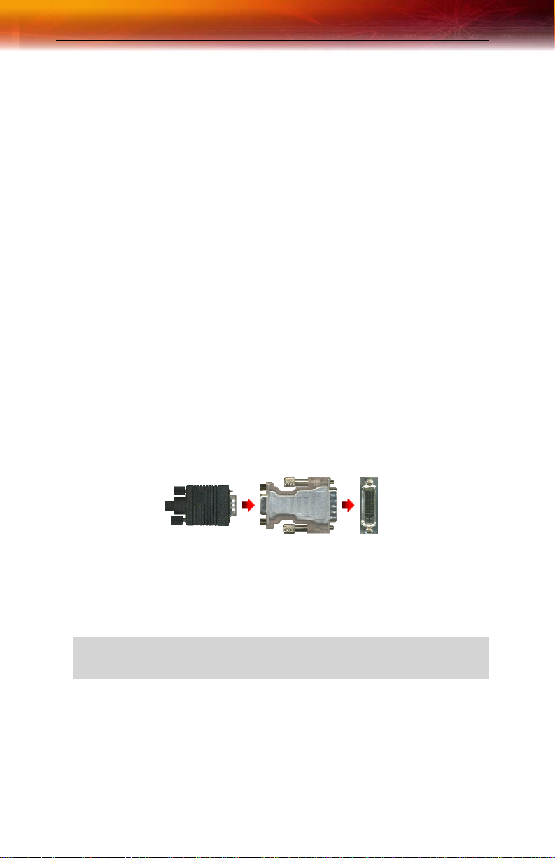
Connecting Display Devices
The following connections are available:
• VGA — for standard VGA monitors
• DVI-I — for digital flat-panel displays
You can connect an analog CRT display using an optional DVI-I-to-VGA
adapter, as shown below.
VGA
CONNECTOR
MONITOR
DVI-I-TO
VGA
ADAPTER
DVI-I
CONNECTOR
ON CARDFROM
Turning on the System
L
If you have properly installed your graphics card, operating system
messages will appear once the boot procedure is finished.
WARNING - Turn on your monitor before you turn on your
computer. Failure to do so could damage your monitor.
Page 25

Input and Output Adapters 17
Your monitor will be running in a basic video mode. Higher refresh rates
are not available at this stage of the installation. Once you have installed the
ALL-IN-WONDER® X800 Series drivers and software you can use the
Display Properties dialog to adjust the video settings and configure
multiple monitors.
Input and Output Adapters
Your ALL-IN-WONDER® X800 Series uses input and output adapters
that let you connect audio and video devices to the card (for example, TV,
VCR, or camcorder).
L
To hear sound when you use your ALL-IN-WONDER® X800 Series
card’s TV feature, ensure that the ALL-IN-WONDER® card’s audio
output cable is connected to your sound card’s line-in connector.
To watch movies on your PC or record video from your VCR or camcorder
Use the ATI input adapter to connect a VCR or camcorder to your ALL-INWONDER® X800 Series card, as shown.
Page 26

18 Input and Output Adapters
Typical VCR or camcorder audio and video output connectors. Use
X
composite video out or S-Video out. S-Video will provide better
results.
Cable with S-Video plug at each end.
Y
Cables with RCA plug at each end, available separately from a
Z
consumer electronics dealer.
ATI Input Adapter . You can snap the adapters together for convenient
[
placement and use.
Input / Output connector.
\
ALL-IN-WONDER® X800 Series card.
]
Page 27
Input and Output Adapters 19
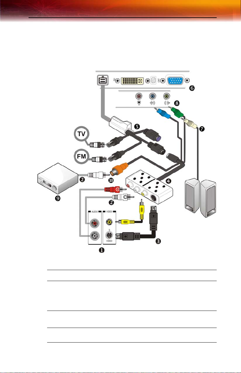
To display your PC output on TV and record PC output on videotape
Use the ATI output adapter to connect a TV, camcorder, or VCR to your
ALL-IN-WONDER® X800 Series card, as shown.
RF1 Cable TV connection.
RF2 Cable FM Radio connection.
Typical VCR or camcorder audio and video input connectors. Use
X
composite video in or S-Video in; S-Video will provide better results.
T o use your TV as a display, you must enable TV Out (see Using TV
Out on page 57.
Cables with RCA plug at each end, available separately from a
Y
consumer electronics dealer.
Cable with S-Video plug at each end.
Z
Page 28

20 Input and Output Adapters
ATI Output Adapter. You can snap the adapters together for
[
convenient placement and use.
Input / Output connector
\
ALL-IN-WONDER® X800 Series card.
]
PC speaker connection (optional).
^
Line-In to sound card (must be connected).
_
Dolby® Digital AC-3 Amplifier.
`
S/PDIF connection.
a
Page 29

Input and Output Adapters 21
To display your PC output on a high-definition TV
Use the ATI output adapter to connect a high definition TV to your ALLIN-WONDER® X800 Series card, as shown.
Input / Output Adapter.
X
ALL-IN-WONDER® X800 Series card.
Y
ATI HD Output Adapter.
Z
Cables with RCA plug at each end, available separately from a
[
consumer electronics dealer.
Page 30

22 Input and Output Adapters
Typical HDTV video inputs.
\
Note: Input and output cable lengths should not exceed 50 feet
(15m).
Y = Green
Pb = Blue
Pr = Red
Cable with mini-stereo plug at each end, available separately from a
]
consumer electronics dealer, for connecting PC speakers (optional).
LINE IN to sound card (must be connected).
^
Dolby® Digital AC-3 Amplifier.
_
Cable with RCA plug at each end, available separately from a
`
consumer electronics dealer.
S/PDIF connection.
a
Page 31

Input and Output Adapters 23
Compatibility with earlier ALL-IN-WONDER® products
If you have input and output devices connected to an earlier ALL-INWONDER® product, the input/output adapter included with your ALLIN-WONDER® X800 Series card lets you easily re-attach those devices.
ATI Input Adapter used with earlier ALL-IN-WONDER® products.
X
RF1 F-connector for cable TV input.
Y
RF2 F-connector for cable FM radio input.
Z
Input connector.
[
ATI Output adapter used with earlier ALL-IN-WONDER® products.
\
Page 32

24 Input and Output Adapters
Input / Output connector.
]
ALL-IN-WONDER® X800 Series card.
^
Page 33

Installing Drivers and Software in Windows® 25
CHAPTER 3:
Installing Sof tware
This chapter will guide you through the installation of the drivers and
software associated with your ALL-IN-WONDER® X800 Series card.
Installing Drivers and Software in Windows®
You will need to install the ALL-IN-WONDER® X800 Series drivers and
software in the following cases:
• After you have installed the card in your system.
• After you have reinstalled or upgraded your operating system.
This procedure applies to Windows® 2000 and Windows® XP.
L
Linux drivers and installation instructions are available from
ati.com/support
Software Installation Prerequisites
To install or remove the drivers, you must have administrator rights or be
logged on as a user with administrator rights.
Your operating system must be installed and running before you can install
the ALL-IN-WONDER® X800 Series drivers. You must also have Service
Pack 1 (or higher) for Windows® 2000 or Windows® XP installed.
Make sure your monitor cable is properly attached before you begin.
Note: The installation dialog will display in English if your operating
system’s language is not supported.
To install ATI drivers and software
1 Start your system. When the Found New Hardware Wizard
comes up, click Cancel. When the System Settings Change
window asks you to restart your computer, click No.
Page 34

26 HYDRAVISION™ Multi-monitor Management
2 Run the ATISETUP utility. The ATISETUP utility will start
automatically if you insert the ATI Installation CD-ROM into your
CD-ROM drive after the operating system has started. If your CDROM auto-run is not enabled or the ATISETUP utility does not start
automatically:
a) Click the Start button in the task bar.
b) Click Run.
c) Select ATISETUP.EXE from the root directory of the ATI
Installation CD-ROM.
d) Click OK.
3 Click Install under Software Install.
4 Click Next.
5 Click Yes to the license agreement. ATI Easy Install will start the
Installation Wizard.
6 Follow the wizard’s on-screen instructions to complete the
installation.
Note: The Express installation option is recommended. The
HYDRAVISION™ multi-monitor and desktop management software
will automatically be installed, along with the ATI driver , by selecting
this option. Not all software components are installed using the
Express installation. Custom installation allows you to select
individual software components for installation.
7 When the Setup complete message appears, select Y es, I want to
restart my computer now and click Finish.
8 After the system reboots, the Found New Hardware message may
display the Digital Signature Not Found message. Click Yes or
Continue to complete the driver installation.
HYDRAVISION™ Multi-monitor Management
The HYDRAVISION™ multi-monitor and desktop management software
will install automatically with the Express driver installation of the
ATISETUP utility. If you do not want to install HYDRAVISION™ , select
the Custom driver installation and clear the HYDRAVISION™ check
box.
For more information concerning HYDRAVISION™ , consult the user’s
guide included on the ATI Installation CD-ROM.
Page 35

Monitor Configuration 27
Monitor Configuration
Once the drivers and software have been installed, you can configure your
monitor.
To configure your primary display
1 Navigate to the Control Panel and choose Display or right-click on
the desktop and choose
2 Choose the Settings tab and select a screen resolution and color
depth that best suit your requirements and your monitor ’s
performance.
3 Click the Advanced button and select the Monitor tab.
4 Choose a refresh rate from the drop-down list.
Properties.
L
WARNING - Choosing a refresh rate unsupported by your monitor
may damage your monitor. Consult your monitor’s documentation if
necessary.
5 Click OK until you return to the desktop.
Reinstalling Drivers
The software installation procedure detailed in this chapter describes how
to install the drivers for your graphics card after you have installed a new
card for the first time and have rebooted your computer.
If you are installing the graphics card drivers in a special working scenario,
such as if you have reinstalled your operating system or want to perform a
manual reinstallation.
To reinstall drivers using the ATISETUP utility
You can always install the drivers using the
Installation CD-ROM. The
you insert the ATI Installation CD-ROM into your CD-ROM drive after the
operating system has started. If your CD-ROM auto-run is not enabled or
the
ATISETUP utili ty does not start automatically, perform the following
actions:
ATISETUP utility will start automatically if
ATISETUP utility on the ATI
1 Click the Start button in the task bar.
2 Select Run.
Page 36

28 Starting the ATI Multimedia Center
3 Browse to ATISETUP.EXE on the root directory of the ATI
Installation CD-ROM and click
To manually reinstall drivers
To manually reinstall drivers, when prompted for a driver installation CD,
insert the ATI Installation CD-ROM and browse to the
subdirectory.
OK.
drivers
Starting the ATI Multimedia Center
From LaunchPad
The LaunchPad provides a convenient way to start all your Multimedia
Center features — just click the one you want. LaunchPad opens
automatically when you start your computer, or if you prefer, you can rightclick LaunchPad, and uncheck Load on Startup in the drop-down menu to
disable this feature.
From Windows® taskbar
1 In the Windows® taskbar, click Start, and then point at Programs.
2 Point at ATI Multimedia Center, and then select the feature you
want to run.
For information on the ATI Multimedia Center, see the User’s Guide
and the online help.
L
The first time you launch TV, you must complete the Initialization
Wizard, which guides you through setting up TV. After that, the
Wizard will not run unless you want to re-run it.
Page 37

Introduction 29
CHAPTER 4:
A TI’ s CATAL YST ™ Sof tware Suite
Introduction
This chapter describes using the advanced multiple-monitor and 3D
graphics features in ATI’s CATALYST™ Software Suite.
The ATI REMOTE WONDER™ software is automatically installed with
the CATALYST™ Software Suite. See the ATI REMOTE WONDER™
Installation Guide for installation instructions.
Features
Multiple Displays and 3D Gaming
ATI’s CATALYST™ Software Suite provides multiple-display
functionality, and its advanced graphic features, such as
SMARTSHADER™ HD, provide the ultimate 3D gaming experience.
The CATALYST™ Software Suite also supports the latest versions of
Direct 3D® and OpenGL®. Many 3D game titles will virtually come to life
through the advanced Direct 3D® or OpenGL®
tune these settings for the ultimate experience in 3D image quality or 3D
gaming performance.
features. Gamers can fine-
HYDRAVISION™
In addition to the multiple display functionality available with ATI’s
CATALYST™ Software Suite, you can also use HYDRAVISION™ for
advanced multi-monitor management. For more information on
HYDRAVISION™ , please refer to the
PDF located on your ATI Installation CD.
HYDRAVISION™ User’s Guide
Accessing the CATALYST™ Software Suite
For help installing the CATALYST™ Software Suite, refer to the Getting
Started Guide
.
Page 38

30 ATI Displays Tab
The CATALYST™ Software Suite installs the ATI display tabs into the
Windows®
Advanced button located on the Settings tab.
Display Properties dialog. They are accessed through the
To access the
navigate through Windows®
menu.
Display Properties dialog, right-click on the desktop or
Control Panel, which is located in the Start
Windows® Display Properties Settings Tab
ATI Displays Tab
The ATI Displays tab provides control over multiple-monitor features.
Here you can enable/disable display devices and swap the assignment of
Primary and Secondary displays.
Page 39

ATI Displays Tab 31
.
ATI Displays Tab
ATI Displays Tab
Scheme Displays the drop-down list of available display-device
configurations that have previously been created. New
configurations can be entered here and then saved using
the Save button.
Hotkey Associates a hotkey with a scheme. To input the hotkey,
highlight the field and press the appropriate key
combination on your keyboard.
Save button Saves display-device configuration schemes.
Delete button Deletes display-device configuration schemes.
Display buttons Enables or disables a display device; they also indicate
whether a device is enabled or disabled.
Page 40

32 ATI Displays Tab
ATI Displays Tab
Troubleshoot
button
Opens a Troubleshoot dialog to assist with possible
display problems.
To enable or disable a display
If the enable/disable button is green, it indicates the device is enabled. If it
is red, it indicates the device is disabled. If the button is greyed out, the
device is not an option. For example, if there is only one monitor
connected, all buttons will be grey.
1 Click the enable/disable button for the display device you
want to enable/disable.
2 Click OK or Apply to save the changes.
Note: Due to power restrictions, you can normally only have two
devices active at the same time; for example, two monitors or a
monitor and a TV.
To save a display-device scheme
Display-device selections can be saved as a scheme for quick recall.
1 Click the enable/disable button for the display devices you
want to have active.
2 Type a name into the Scheme drop-down list field.
3 Click Save to save the scheme.
Dynamic Display Reassignment
You can change the assignment of your Primary and Secondary display on
the fly, without rebooting.
Note: Before you can change the assignment of the Primary display,
at least one Secondary display and the Extended Desktop mode must
be enabled. Extended Desktop mode is enabled through the
Windows®
information, consult your Windows®
To assign your Primary monitor
1 Click the buttons to assign the Primary monitor:
Display Property dialog, under Settings. For more
documentation.
Page 41

ATI Color Tab 33
For Windows® XP
• The ATI Displays tab shows you the display(s) that are active.
The Primary display has the button depressed. To change the
display assignment, click the Primary display’s button or
click the button of the other display device.
For Windows® 2000
• Clicking the button will reassign the Primary and Secondary
monitors. Clicking the button creates a clone or mirror
image of the Primary display onto the Secondary display.
Clicking the button extends your desktop to a Secondary
display located to the right of the Primary display. Clicking the
button extends your desktop to a Secondary display located
below the Primary display.
2 Click OK or Apply to save the changes.
ATI Color Tab
The ATI Color tab allows you to configure Gamma, Brightness, and
Contrast color settings for both your desktop and full screen 3D
environments. You can also save settings to a color profile for easy recall.
In addition, you can assign unique hotkey combinations that allow you to
adjust Gamma, Brightness, and Contrast color settings within your full
screen 3D applications.
Page 42

34 ATI Color Tab
ATI Color Tab: Desktop Settings
Page 43

ATI Color Tab 35
ATI Color Tab: Full Screen 3D Settings
ATI Color Tab
Desktop radio
button
Full Screen 3D
radio button
Profiles for Indicates whether the profiles in the drop-down list are for
Profiles dropdown list
Select Desktop to configure your desktop color settings.
Select Full Screen 3D to configure the color settings for
your 3D application. Note that the configured settings will
only be apparent within a full screen 3D application
environment.
your Desktop or a Full Screen 3D environment.
Lists all of the Desktop or Full Screen 3D profiles that you
have saved. Selecting a profile from the list loads those
custom color settings for the relevant environment. To
create a new profile, simply type in a name and click Save.
Page 44

36 ATI Color Tab
ATI Color Tab
Save button Saves your current color settings to a Desktop or Full
Delete button Deletes the profile that is selected in the Profiles list box.
All Colors
checkbox
Red, Green, and
Blue radio
buttons
Gamma slider Increases or decreases the gamma correction of your
Brightness slider Increases or decreases the color brightness of your
Contrast slide Increases or decreases the color contrast of your Desktop
Reset buttons Restores an individual slider setting to its default value.
Screen 3D profile, using the name you specified in the list
box. To restore these settings later, simply select the
Profile name from the list and click Apply or OK.
Adjusts the Gamma, Brightness or Contrast for Red,
Green, and Blue simultaneously. Note that any individual
color settings in effect are lost if All Colors is selected; the
color settings revert back to the last-known All Colors
settings.
Selects the active color component (Red, Green, or Blue)
whose values will be adjusted by the Gamma, Brightness,
and Contrast sliders. Note that any individual color settings
made are lost if you subsequently select All Colors.
Desktop or full screen 3D application. Changing the
gamma alters the curvature of the color curve.
Desktop or full screen 3D application. Changing the
brightness adjusts the vertical position of the color curve.
or full screen 3D application. Changing the contrast
adjusts the slope of the color curve.
Click Apply or OK to save.
Color preview
box
Hotkeys button Opens the Color Hotkeys Settings dialog. There you can
Defaults button Restores all of the color settings to the default values.
The color image indicates visually how the Gamma,
Brightness and Contrast sliders affect the final color
settings of your display device. In Desktop mode, clicking
on this with your mouse pointer will change the image.
assign hotkeys for adjusting your color settings within a full
screen 3D application environment. To activate this button,
you must select the Full Screen 3D radio button.
Click Apply or OK to save.
To create a Desktop or Full Screen 3D profile
1 Choose either the Desktop or Full Screen 3D radio button, as
desired.
Page 45

ATI Color Tab 37
2 Adjust the Gamma, Brightness, and Contrast sliders to the desired
settings, either individually or using the
All Colors checkbox.
3 Type a profile name in the Profile list box.
4 Click Save.
To apply the settings for a specific Desktop profile
1 Choose the Desktop radio button.
2 Select the profile name from the drop-down list box.
3 Click Apply or OK.
To apply the settings for a
Full Screen 3D profile
1 Choose the Full Screen 3D radio button.
2 Select the profile name from the drop-down list box.
3 Click Apply or OK.
4 Start your 3D application in full-screen mode.
Hotkeys
Some 3D applications automatically load their own color settings rather
than those set through the ATI Color tab. To use custom settings, you can
preconfigure hotkey combinations to either adjust the individual color
properties or apply profiles you have created, once the 3D application is
running.
To access the Color Hotkeys Settings dialog
1 Select the Full Screen 3D radio button.
2 Click the Hotkeys button to access the Color Hotkeys Settings
dialog.
The easiest way to apply your own color settings from within a full screen
3D application is to create a Full Screen 3D profile and save it, assign
hotkeys for the “Load Current Profile” action through the Hotkeys dialog,
make sure that the profile you prefer is selected from the drop-down list
box, and click
trigger the profile.
OK. Once inside the 3D application, use the hotkeys to
Page 46

38 Color Hotkeys Settings
Some 3D applications allow you to switch easily between full-screen mode
and windowed mode, and do not load their own color settings. In windowed
mode, you can make slider adjustments or select a different profile on the
Color tab, then switch back to full-screen mode to see the effects
immediately.
Color Hotkeys Settings
Some full screen 3D applications automatically load their own color
settings rather than those set through the ATI Color tab. If you want to force
the application to use your custom settings, you can preconfigure hotkey
combinations to either adjust the individual color properties or apply
profiles you have created from within the 3D application. This control is
accomplished through the Color Hotkeys Settings dialog of the Color
properties tab.
Color Hotkeys Settings Dialog
Page 47

Color Hotkeys Settings 39
Color Hotkey Settings
Modifier key In combination with the Hotkey, specifies the hotkey
combination that triggers an action. The Modifier key can
be any combination of Alt, Ctrl, or Shift. Note that the Shift
key is never used alone.
Hotkey In combination with the Modifier key, specifies the hotkey
combination that triggers an action. Hotkey can be any
key listed. To avoid conflicts, be aware of any hotkeys or
keyboard controls that may already be assigned to your
applications and 3D games.
Hotkey action Specifies the action that the assigned hotkey
Assigned
hotkeys
Add button Adds a hotkey combination to the assigned list.
Remove button Removes a hotkey combination from the assigned list.
Disable hotkeys
checkbox
combinations will control within a full screen 3D
application environment. You can only assign one hotkey
combination to each action.
Lists the assigned hotkey combinations and the actions
that each one controls.
Disables all hotkeys. To disable a single hotkey
combination, remove it from the assigned list.
To assign color settings hotkeys for full screen 3D
applications
1 Select a modifier key from the Modifier Key list.
2 Select a hotkey from the Hotkey list.
3 Select the action you want from the Hotkey Action list.
4 Click Add to create the hotkey combination. This combination will
appear in the Assigned Hotkeys text box. Only one hotkey
combination can be assigned to each action; if you assign a new
combination for an action, it will overwrite an existing one.
Note: When assigning hotkeys, be careful that the key combinations
you choose do not conflict with those of other applications in which
you might want to use them. The ATI Color properties page only
checks for duplications within the Color page itself, insofar as it
allows a hotkey combination to be assigned only once.
Page 48

40 ATI Options Tab
To remove assigned hotkeys
1 Select a hotkey combination from the Assigned Hotkey text box.
2 Click Remove.
Note: Assigning a new combination to an action with an existing
combination will overwrite the existing one.
To disable hotkeys (so that you do not accidentally activate them, for
example), click the
hotkeys, make sure this box is unchecked.
The easiest way to apply your own color settings from within a full screen
3D application is to create a Full Screen 3D profile and save it, assign
hotkeys for the “Load Current Profile” action through the Hotkeys dialog,
make sure that the profile you prefer is selected from the drop-down list
box, and click
trigger the profile.
Disable Hotkeys checkbox. If you plan to use
OK. Once inside the 3D application, use the hotkeys to
ATI Options Tab
The ATI Options tab provides detailed driver information and access to
your graphics card’s versioning and specifications. You can also enable or
disable the ATI taskbar icon from this dialog.
Page 49

ATI Options Tab 41
ATI Options Tab
ATI Options Tab
Version
Information
Details button Gives access to the Details tab, which lists the card’s
Reactivate all
warning
messages
Enable ATI
taskbar icon
application
Show ATI icon on
taskbar
Disable quick
resolution feature
Shows the Catalyst version number, 2D version number,
and the driver build information.
hardware details and driver information.
Reactivates any disabled graphics warning messages.
Enables/disables the ATI taskbar applications and
removes the ATI icon from your system tray.
Removes/replaces the ATI icon from the system tray
without disabling the ATI icon applications.
The quick resolution feature is accessible by left-clicking
the ATI icon in the system tray. Checking this option
disables this feature.
Page 50

42 ATI Rotation Tab
ATI Options Tab
Reduce DVI
frequency on
high-resolution
Alternate DVI
operational mode
Resolves display corruption or no image at high
resolutions (for example 1280x1024 @75Hz) using a
digital DVI display. This setting has no effect when using a
DVI-I-to-VGA adapter.
Use this option if you are experiencing display corruption
on your DVI flat panel.
ATI Rotation Tab
Use the Rotation tab to rotate the image on your display up to 180 degrees.
This feature is useful when using a flat panel display that can be physically
rotated to different positions.
ATI Rotation Tab
Page 51

ATI Rotation Tab 43
A TI Rotation Tab
Rotation buttons Rotates the display by the preset amount.
Configure
Hotkeys dropdown list
Hotkey field Associates a hotkey with a rotation. To input the hotkey,
Save button Saves a hotkey setting.
Defaults Restores the default hotkey settings.
Mouse tracks
rotation
checkbox
Lists the rotation actions with which you can associate a
hotkey.
click on the field and press the appropriate key
combination on your keyboard.
When selected, rotates the mouse pointer to match the
display image settings. When deselected, the mouse
pointer will move relative to the Standard Landscape view
regardless of display rotation.
To rotate a single display
1 Select one of the four rotation settings by clicking the appropriate
button.
2 Optionally, check the Mouse Tr ack Rotation checkbox to have the
mouse pointer match the display image.
3 Click OK or Apply.
To rotate multiple displays
1 Select the Settings tab in the Windows® Display Properties
dialog.
2 Select the display to which you want to apply the rotation.
3 Click the Advanced button and select the Rotation tab.
4 Select one of the four rotation settings by clicking the appropriate
button.
5 Optionally, check the Mouse Tr ack Rotation checkbox to have the
mouse pointer match the display image.
6 Click OK or Apply.
Page 52

44 ATI Overlay Tab
Rotation HotKeys
Hotkeys can be assigned to quickly rotate the image on your display
without having to access the Windows®
To assign rotation ho tkeys
Display Properties dialog.
1 Choose the required rotation setting from the Configure HotKeys
drop-down list.
2 Click on the HotKey field and press the appropriate key combination
on your keyboard.
3 Click Save.
Note: When assigning hotkeys, be careful that the key combinations
you choose do not conflict with those of other applications in which
you might want to use them. The ATI Rotation page only checks for
duplications within the Rotation page itself, insofar as it allows a
hotkey combination to be assigned only once.
ATI Overlay Tab
The ATI Overlay tab allows you to configure the brightness, contrast,
saturation, hue, and gamma properties of your video overlay.
Video Overlay
Video overlay allows for the viewing of streaming video on your PC.
However, there is only one video overlay, which is only available on the
Primary display. The video overlay controls are automatically activated
during playback of any video file type that supports overlay adjustments.
Move the sliders to the right to increase the values of the various options,
and to the left to decrease them.
Click the
Defaults button to reset the values to their default settings.
Page 53

ATI Overlay Tab 45
ATI Overlay Tab
ATI Overlay Tab
Brightness Adjusts the brightness of the video image.
Contrast Adjusts the contrast in the video image.
Saturation Adjusts the vividness of the color. Sliding it all the way to
the left removes all color and produces a black and white
picture.
Hue Adjusts the pureness or tint of the red, green, and blue
components of the color.
Gamma Adjusts the overall intensity of the video image.
Clone mode
options
Defaults button Resets the Overlay settings to default values.
Accesses Clone Mode overlay settings.These settings
only apply to video content when viewed in dual-controller
Clone mode. For more information, see the Clone Mode
Settings section.
Page 54

46 ATI Overlay Tab
ATI Overlay Tab
Theater Mode Displays video playback in full screen on a secondary
monitor, if available and enabled.
Clone Mode Settings
Clone Mode Options are available under the following conditions:
• Your ATI graphics accelerator has dual controllers to support
Primary and Secondary (Clone) displays.
• Your ATI video adapter ha s dual display functionality by providing
a standard VGA connector and a digital flat panel connector such as
the DVI-I connector.
In either of these cases, you can access Clone Mode Options if more than
one display is connected.
Note: These settings apply to video content viewed when you are in
dual-controller Clone mode, and not single-display or extended
desktop configurations.
Clone Mode Options tab
Page 55

ATI 3D Tab 47
Clone Mode Options
Standard Video content is displayed on your Primary display only.
Theater Mode Video content is displayed on your Primary and Secondary
displays. Video content is displayed on your Secondary
display(s) is always in full screen mode. Note: your
computer must be set for 16-bit color depth or higher to
use this mode.
Same on all Video content is displayed on your Primary and Secondary
Theater Mode
Settings
Same as source
video
Full Screen Video The source video is scaled so that your display is showing
4:3 (Standard TV) Select this option if the aspect ratio of the display device
16:9 (Widescreen) Select this option if the aspect ratio of the display device is
display in exactly the same manner. For example, all
displays will show video output in full screen mode.
These settings are available when Theater Mode is
selected.
The aspect ratio of the source video is maintained for full
screen display. Note: that this option may result in black
bars on either the horizontal or vertical sides of the video
display.
full screen. Note: if the source video contains horizontal
black bars, as do some DVD movies, the full screen video
will also contain black bars.
showing full screen video has the standard 4:3 aspect
ratio (standard TVs and monitors).
showing full screen video has a 16:9 aspect ratio
(widescreen HDTVs).
ATI 3D Tab
This tab allows you to fine-tune settings for both Direct 3D® and
OpenGL® applications. It displays existing settings and allows you to
create unique application profiles.
Page 56

48 ATI 3D Tab
ATI 3D Tab
ATI 3D Tab
3D Settings for
radio buttons
Performance/Quality
slider
Use Custom Settings
checkbox
Custom button Opens the Custom Properties dialog. Using
Selects either Direct 3D® or OpenGL® as the
format to be altered in the workspace.
Controls the overall performance/image quality of
your graphic application. Moving the slider to the
left will maximize application performance, while
moving the slider to the right will maximize image
quality.
When Use Custom Settings is checked, the
Performance/Quality slider is disabled and the
Custom button is enabled. Using custom settings
is recommended for advanced users only.
custom settings is recommended for advanced
users only. For more information, refer to the
Custom Properties Dialog section.
Page 57

ATI 3D Tab 49
ATI 3D Tab
Current Settings Shows the current settings for either Direct 3D®
or OpenGL®, whichever is selected.
Profiles for Allows you to save a unique profile of the custom
settings you have selected. Once you have
completed making your custom settings, click OK
in the Custom Properties dialog. Enter a name in
Current Profile and click the Save button.
Saved profiles are selected from the Current
Profile drop-down window.
To delete a profile, select it from the Current
Profile drop-down window and press the Delete
button.
Compatibility Settings
button
Defaults Resets to the dialog’s default values.
Accesses advanced settings that may solve
compatibility issues for a few specific Direct 3D®
or OpenGL® applications, whichever is selected.
For more information, refer to the Compatibility
Dialog section.
Page 58

50 ATI 3D Tab
Custom Properties Dialog
Custom Properties Dialog
Custom Properties Dialog: OpenGL® or Direct 3D®
SMOOTHVISION™
HD Anti-Aliasing
slider
SMOOTHVISION™ (Anti-Aliasing) improves image
quality by removing jagged edges from 3D images,
resulting in smoother, more natural-looking objects. AntiAliasing can be applied using different sample patterns
and sample points such as 2X or 4X. Moving this slider
to the right increases sampling to provide the most
realistic 3D image.
Select the Application Preference checkbox for highquality images, with a negligible reduction in the
application’s performance.
Deselect the Application Preference checkbox to
customize the anti-aliasing.
Page 59

Custom Properties Dialog: OpenGL® or Direct 3D®
ATI 3D Tab 51
SMOOTHVISION™
HD Anisotropic
Filtering slider
Texture Preference
slider
Mipmap Detail
Level slider
Anisotropic filtering uses a texture filtering technique
that blends multiple texture samples together. The
number of samples taken when anisotropic filtering is
performed can vary. By moving this slider to the right, as
the number of samples taken increases, the quality of
the final image increases significantly. 16X provides
extremely detailed, crisp-looking images as a result of
the largest number of texture samples possible.
Selecting the Application Preference checkbox will
result in high-quality images, with a negligible reduction
in the application’s performance.
Select the Application Preference checkbox for highquality images, with a negligible reduction in the
application’s performance.
Deselect the Application Preference checkbox to
customize the anisotropic filtering.
Choose between high quality or high performance
textures for your application. Moving the slider to the
right delivers the highest quality experience. Moving the
slider to the left emphasizes a high-performance solution
while still providing good visuals.
Choose the texture quality of the mipmaps the
application will use. Mipmaps are a collection of different
sized textures of the same image. As the user moves
closer to a 3D object the image quality should increase,
requiring a higher quality texture of the same image. The
base mipmap is the highest quality texture, and all
subsequent mipmaps are smaller sized textures of the
same image. Moving the slider to the right selects a
higher quality base mipmap, delivering the highest
quality application experience. Moving the slider to the
left selects a lower quality mipmap, delivering the
highest application performance.
Wait for Vertical
sync slider
TRUFORM™ slider TRUFORM™ is a technology developed by ATI that
Controls whether the Vertical sync is always on, always
off, or controlled by the application.
enables higher-order surface rendering through
traditional triangle rendering APIs. It improves the
sillouhettes and lighting of objects.
Page 60

52 ATI 3D Tab
Custom Properties Dialog: SMARTSHADER™ Effects
SMARTSHADER™
Effects drop-down
list
Defaults button Restores the default settings.
SMARTSHADER™ applies preset pixel effects on
OpenGL® or Direct 3D® applications. Choose the
desired effect and click OK.
Page 61

Direct 3D® Compatibility Settings
Direct 3D® Compatibility Settings Dialog
ATI 3D Tab 53
Direct 3D® Compatibility Settings
Support DXT
texture formats
Alternate pixel
center
Defaults button Resets to the dialog’s default values.
There are a few applications that can only support a
limited number of texture formats. By selecting Disabled,
the driver will not support DXT texture formats, thus
reducing the number of texture formats supported.
May eliminate problems with some Direct 3D® games
which display vertical and horizontal lines around
textures, or text that appears incorrect. However, this
setting should only be used if you are experiencing the
symptoms mentioned, as it may cause problems with
other games.
Page 62

54 ATI 3D Tab
OpenGL® Compatibility Settings
OpenGL® Compatibility Settings Dialog
OpenGL® Compatibility Settings
Force Z-buffer
depth
Triple Buffering Improves the frame rate of games when Wait for Vertical
Defaults button Resets to the dialog’s default values.
OpenGL®
hardware
acceleration
Explicitly set the Z-Buffer depth. Most applications will
work best when Disabled is selected
Sync is enabled in Custom Settings. Enabling Triple
Buffering may decrease application performance as
there will be less frame-buffer memory available. If there is
insufficient memory available to support this feature it will
be automatically disabled. It is recommended that this
feature remain disabled.
This feature should only be disabled if you are
experiencing serious rendering problems. Disabling this
feature will significantly decrease OpenGL® performance.
Page 63

ATI 3D Tab 55
ATI VPU Recover Tab
Hardware crashes may occur when a hardware device and the
corresponding software device driver are no longer able to communicate
with each other. VPU Recover enables the ATI display driver to detect
when the graphics card is no longer able to respond to display driver
commands. When this situation arises, the display driver will reset the
graphics card. Depending on the current state of the system when VPU
Recover is activated, applications that are running may be able to fully
recover from this reset. In other cases, running applications may be closed,
and the user will be returned to the Windows® desktop.
ATI VPU Recover Tab
ATI VPU Recover Tab
Enable VPU Recover
checkbox
Enables VPU Recover.
Page 64

56 ATI 3D Tab
ATI VPU Recover Tab
Prepare an Error Report
checkbox
When VPU Recover is activated a dialog will
prompt you to submit an automatically generated
error report to ATI. This error report will help ATI to
determine the cause of the problem and help
create more stable drivers. T o disable this feature,
deselect the Prepare an Error Report checkbox.
Page 65

Using TV Out 57
CHAPTER 5:
Using TV Display and Capture Features
Using TV Out
Your ALL-IN-WONDER® X800 Series has TV Out capability. It also
supports YPbPr component video output. For European customers,
SCART-out is supported; an SCART plug and cables are included with the
card.
Viewing Your PC’ s Display on a TV
You can attach your graphics card to a TV and monitor at the same time.
You can also connect it to your VCR and record your monitor’s display.
L
TV display is ideal for giving presentations and watching movies, or
playing games on a screen larger than a typical monitor. The following tips
will help you get the most out of your TV Out feature.
IMPORTANT INFORMATION for European Customers
Some PC monitors in Europe cannot be used simultaneously with TV
display. When you enable TV display in Europe, the refresh rate for the
monitor and TV is set to 50 Hz. Some monitors may not support this
refresh rate and could be damaged.
• Please check the documentation supplied with your monitor to see if
your monitor supports a refresh rate of 50 Hz.
• If your monitor does not support 50 Hz (or if you are not sure), turn
off your monitor before turning on your PC when using your TV as a
display.
Connecting to a TV or VCR
To connect your ALL-IN-WONDER® X800 Series card to a TV or VCR,
use an S-Video cable. Many TVs (and VCRs) have a Composite video
input, in which case you can use the supplied S-Video-to-Composite video
adapter. If your TV has cable input only, you can connect your graphics
card to your TV through your VCR or an RF modulator that is available
from most electronics stores.
Page 66

58 Using TV Out
Starting Windows® with TV Display Enabled
The TV screen may become scrambled during the initial Windows® logo
display. This distortion is only a temporary effect, and your screen will be
restored within a few seconds.
During start up, your ALL-IN-WONDER® X800 Series will go through a
sequence of mode settings, during which your TV display will remain
blank. This process takes only a few seconds and programs the TV display.
To enable or disable the TV display
1 Access the Windows® Control Panel. Double-click Display.
2 Click the Settings tab and then the Advanced button.
3 Click the ATI Displays tab. Click the TV button.
4 Click the enable button or disable button accordingly.
5 Click OK or Apply to save the changes.
Using and Adjusting TV Display Features
For information about how to adjust TV display features, right-click the
ATI taskbar icon, point to Help, then point to ATI Television Display.
TV Display Hardware Restrictions
A TV cannot be left connected to the graphics card if two analog monitors
are connected to your ALL-IN-WONDER® X800 Series card, even if the
TV is off and not enabled in the software.
Similarly, an analog monitor connected to the DVI-I connector should not
be left connected to your ALL-IN-WONDER® X800 Series card when TV
Out is enabled. In both cases, your ALL-IN-WONDER® X800 Series will
become overloaded, resulting in a dim image on all devices.
Using a Monitor vs. Using TV Display
Using your TV for your computer’s display can be useful, however, the
display on your monitor may change or look squashed. This distortion
occurs because the display adjusts to fit the dimensions of your TV. To
correct the monitor’s display, use the monitor’s control buttons to adjust its
display size and position.
Some single-frequency monitors may not work with TV display enabled. If
you experience problems when TV display is enabled, disable TV display
to restore your monitor’s display.
Page 67

Using TV Out 59
Adjusting Monitor Display
The size of the display on your monitor may become smaller and not
perfectly centered when you have TV display enabled. These effects are
caused by the changes required to provide a proper display on the TV.
Use the controls available on the Adjustments tab on th e Monitor
Properties page (accessible by clicking on the Monitor button on the ATI
Displays tab) to adjust the display on your monitor only. Click the TV
button to adjust the TV display only.
Viewing Text on a TV
A TV is designed primarily to show moving images. The large dot pitch of
a TV will yield poor quality static images. The small text sizes commonly
used for PC desktops can appear blurred or unclear on a TV. You can
compensate for this degradation by using larger fonts.
Switching to a larger display font
1 Access the Display Properties dialog by right-clicking on the desktop
or navigating through Windows®
2 Click the Settings tab, the Advanced button, and then the General
tab.
Control Panel.
3 In the Display section, select Large (120 DPI) from the Font Size
(or DPI Setting) drop-down list.
4 Click Apply. If prompted, click Yes to restart your Computer.
Reducing Edge Distortion
When using a TV for your computer’s display, you may see some edge
distortion on the left and right side of your TV screen. This effect depends
on your TV and the computer application you are running.
You can reduce edge distortion by increasing the TV display’s horizontal
size or contrast.
Increasing the horizontal size of a TV display
1 Access the Display Properties dialog by right-clicking on the desktop
or navigating through Windows®
2 Click on the Settings tab and then the Advanced button.
3 Click on the ATI Displays tab.
4 Click on the TV button.
Control Panel.
Page 68

60 Using TV Out
5 Click the Adjustments tab.
6 In the Screen Size section, click on the plus (+) button beside the
horizontal arrowheads to increase the horizontal size of the TV
display.
7 Click OK or Apply to save the changes you have made.
You can also reduce edge distortion by increasing the TV’s contrast.
Increasing the contrast of a TV display
1 Access the Display Properties dialog by right-clicking on the desktop
or navigating through Windows®
Control Panel.
2 Click on the Settings tab and then the Advanced button.
3 Click on the ATI Displays tab.
4 Click on the TV button.
5 Drag the Contrast slider to the right to increase the contrast.
6 Click OK or Apply to save the changes you have made.
Using TV Display Alone
If you plan to move your computer to a place where you are using TV
display only, make sure that you have the TV display feature enabled prior
to removing the monitor.
The maximum display resolution for TV is 1024x768. Choosing a
resolution higher than this will cause the TV display to disappear if it is the
only display device.
Using Games and Applications
Some older games and applications may program your ALL-INWONDER® X800 Series directly to run under a specific display mode.
This may cause your TV display to turn off automatically or become
scrambled (the PC monitor will not be affected). Your TV display will be
restored once you exit the game or if you restart your computer.
Page 69

Using TV Out 61
Using SCART Connectors for European Televisions
Connect to
TV or VCR
Audio In
(Right = Red)
(Left = White)
Connect to
audio source
Cable 1
SCART
Connector
Cable 2
Video In (Yellow)
Connect to
graphics card
Using an SCART connector with a Composite cable
The SCART connector supports only the Composite video format, which
is the most common type. The above illustration shows how to connect to
an SCART connector using a Composite cable.
Page 70

62 Using TV Out
Page 71

CHAPTER 6:
Using Multiple Displays
Connecting Your Monitors
Your ALL-IN-WONDER® X800 Series provides hardware support for
one DVI-I monitor or two VGA monitors using the optional DVI-I-to-VGA
adapter. A TV can also be used to expand your desktop by using the
S-Video out.
63
Connections and Adapters for the ALL-IN-WONDER® X800 Series
Card
X
Y
Standard VGA Monitor Connector. To connect a VGA monitor
to the DVI-I connector, plug the supplied DVI-I-to-VGA adapter
into the DVI-I connector, then plug your monitor cable into the
adapter.
DVI-I-to-VGA Adapter (optional).
Page 72

64
Connections and Adapters for the ALL-IN-WONDER® X800 Series
Card
Z
Note: If you use multiple monitors, the ALL-IN-WONDER® X800
Series card must be the primary graphics card. Normally, the system
BIOS determines which graphics card will be the primary.
To connect your monitors
DVI-I Backplate Connection. To connect a flat panel, plug the
monitors DVI-I connector into the DVI-I connection.
1 Turn off your computer and monitors.
2 Plug the monitor cables into their appropriate connectors.
3 Turn on your monito rs first, and then restart your computer so that
Windows® can detect the new hardware settings.
4 When the New Hardware Found Wizard appears, at the appropriate
prompt insert the ATI Installation CD to load the drivers for your
ALL-IN-WONDER® X800 Series card.
To set up a multi-monitor display
1 From the Start menu click Control Panel, then Display. Click the
Settings tab to access the basic multi-monitor configuration settings.
Note: ATI software provides many additional configuration features
that can be accessed by clicking the
Display Properties > Settings tab.
Advanced button from the
2 Select the Monitor icon identified by the number 2.
3 Click Extend my Windows desktop onto this monitor.
4 Set the Screen Resolution and Color Quality as appropriate for the
second monitor. Click
• Refer to your Windows online help and documentation for
further information on using the
Note: When you use multiple monitors with your card, one monitor
will always be Primary. Any additional monitors will be designated
as Secondary.
Apply or OK to apply these new values.
Settings tab.
Page 73

Display Configurations 65
Display Configurations
Your ALL-IN-WONDER® X800 Series graphics card provides dual
display functionality and TV Out. The following table lists the different
ways you can connect displays to your card.
Display
Configuration
Single CRT
display
Single DFP
display
Single TV S-Video Out The S-Video out can also support a
Single HDTV
display
CRT display + TVVGA connector +
CRT display +
HDTV
DFP display + TVDVI-I connector +
DFP display +
HDTV
Connector(s)
Comments
Used
VGA connector OR
DVI-I connector
with DVI-I-to-VGA
adapter
DVI-I connector DFP - digital flat panel display.
HDTV Output
Adapter
S-Video Out
VGA connector +
HDTV (YPrPb)
output cable
S-Video out
DVI-I connector +
S-Video Out to
HDTV (YPrPb)
cable
CRT- cathode ray tube analog display.
composite connection via the
S-Video-to-Composite adapter.
HDTV - High Definition Television
UNSUPPORTED CONFIGURATION
if the CRT display is attached to the
DVI-I connector via the DVI-I-to-VGA
adapter.
CRT display +
DFP display
CRT display +
CRT display
CRT display +
DFP display +
TV
VGA connector +
DVI-I connector
VGA connector +
DVI-I connector
with DVI-I-to-VGA
adapter
VGA connector +
DVI-I connector +
S-Video Out
The DVI-I connector can support a
CRT display using the DVI-I-to-VGA
adapter
The TV display will “clone” the image
of one of the other two displays
Page 74

66 Display Configurations
Display
Configuration
CRT display +
DFP display +
HDTV
CRT display +
CRT display +
TV
CRT display +
CRT display +
HDTV
CRT display +
European TV
DFP +
European TV
European TV + TVSCART + TV
Connector(s)
Used
VGA connector +
DVI-I connector +
HDTV (YPrPb)
output cable
VGA connector +
DVI-I connector
with DVI-I-to-VGA
adapter +
S-Video Out
VGA connector +
DVI-I connector
with DVI-I-to-VGA
adapter +
S-Video Out to
HDTV (YPrPb)
cable
SCART + VGA
Connector
SCART + DVI-I
(S-Video /
composite video)
Comments
UNSUPPORTED CONFIGURATION
UNSUPPORTED CONFIGURATION
UNSUPPORTED CONFIGURATION
UNSUPPORTED CONFIGURATION
Page 75

MULTVIEW™ 67
MULTVIEW™
If you have an ALL-IN-WONDER® Series card and an ATI TV
WONDER™ PCI card installed in the same system, MULTVIEW™ lets
you watch a different channel in a secondary video window. You can
record video from your ALL-IN-WONDER® while you watch another
channel on the TV WONDER™. The secondary window can be in the
following locations:
Picture in Picture (PiP). When the main video window is in full-screen, the
MULTVIEW™ PiP video window is embedded in the main window. It
can be positioned in the top/bottom left or top/bottom right of the main
window.
Picture outside Picture (PoP). If you use only one monitor, the main and
MULTVIEW™ video windows can be displayed in separate windows. If
you use dual monitors, you can drag the MULTVIEW™ window to the
secondary monitor. MULTVIEW™ can be displayed in a window or full-
screen in the secondary monitor.
L
MULTVIEW™ controls include channel up/down, Mute/unmute, audio,
swap channel, volume slider, and channel status. When MULTVIEW™ is
in focus, you can also type a channel number or name to change channels.
To enable MULTVIEW™
In the MULTVIEW Initialization Wizard, click Enable MULTVIEW.
To open and close MULTVIEW™
The first time you start TV, the MULTVIEW™ Initialization Wizard will
guide you through setting up the MULTVIEW™ window location and
the MULTVIEW™ tuner audio connection.
1 Right-click the control panel or the video panel.
2 In the Feature menu, click MULTVIEW, and then click Show.
T o close MULTVIEW™, click the Close button or right-click the
control panel or the video panel, and in the Feature menu, click
MULTVIEW, and then click Show.
To change the location of the MULTVIEW™ window
When the main video window is in full screen, right-click the control panel
or the video panel, click MULTVIEW, click Location, and then click the
position you want: Top-Left, Top-Right, Bottom-Right, or Bottom-Left.
Page 76

68 EAZYLOOK™
You can manually change the embedded window's size and location when
the MULTVIEW™ borders are visible.
Autohiding MULTVIEW™ window controls and borders
The MULTVIEW™ window borders disappear after a few seconds of
mouse inactivity on the MULTVIEW™ window. When you move your
mouse over the MULTVIEW™ window, the border re-appears.
Only one video window can be in control. When the embedded
MULTVIEW™ window is in focus, its borders are red; when it is not in
focus, its borders are black. For example when the borders are red, a
REMOTE WONDER™ channel-change command will change the
MULTVIEW™ channel.
MULTVIEW™ audio requirements
If you have one audio card or an integrated audio chip, you must connect
one audio path internally (CD-In, for example) and the other externally
(Line-In, for example).
If you have two audio cards or one audio card and an integrated audio chip,
you can connect both audio paths internally, externally , or one int e rnal ly
and the other externally.
EAZYLOOK™
Designed to work with the REMOTE WONDER™ (see page 29) in fullscreen mode, EAZYLOOK™ displays large, on-screen information about
remote control functions when you watch TV, DVD, or File Player. It also
provides assistance when you use the Library or navigate in TV Listings.
Page 77

Uninstalling Old Graphics Card Software 69
CHAPTER 7:
T roubleshooting
The following troubleshooting tips may help if you experience problems.
ATI’s documentation contains helpful installation/configuration tips and
other valuable feature information. Please contact your dealer for more
advanced troubleshooting information.
More troubleshooting information can be found on the ATI Website at
ati.com/support/.
Uninstalling Old Graphics Card Software
To ensure successful installation of your ALL-IN-WONDER® X800
Series card, you must uninstall the graphic drivers for the existing graphics
card before removing it from your computer.
To uninstall old graphics drivers
1 With your current graphics card still in your computer, close all open
applications.
2 Click Start > Settings > Control Panel, then select Add/Remove
Programs
.
3 Select your current graphic drivers, then click Add/Remove:
• The Wizard will help you remove your current display drivers.
• Restart your system after the drivers have been removed.
If the previously installed graphics card has any additional software
L
installed, they may also need to be removed at this point. For example,
DVD Player or Multimedia applications.
Windows® New Hardware Found
Windows may start the Add New Hardware Wizard to install the
Standard VGA Driver.
Page 78

70 Installing the CATALYST™ Software Suite
To install and detect your new hardware
1 Click Next to allow Windows® to search for the Standard VGA or
Standard PCI Graphics Adapter.
If prompted for the Windows® CD-ROM, insert it into your CD-ROM
drive.
2 Type the following: D:\<Operating System name> for example
D:\WinXP.
If
D is not your CD-ROM drive, substitute D with the correct drive
letter.
3 Click OK.
4 Click Finish to close the Wizard and then restart your system.
Installing the CATALYST™ Software Suite
ATI’s CATALYST™ software suite provides you with all you need to get
the most out of your ATI Graphics Accelerator card. The CATALYST™
software suite comprises four, distinct software elements:
•Driver.
• Multimedia Center.
• HydraVision (not included in the Express Install).
• Remote Wonder Software.
To ensure you install supported software, use the ATI Installation CDROM that shipped with your ATI Graphics Accelerator card.
To install the CATALYST™ Software Suite
1 Insert the ATI INSTALLATION CD-ROM into your CD-ROM drive.
If Windows® runs the CD-ROM automatically, proceed to step 6.
2 Click Start.
3 Select Run.
4 Type the following: D:\ATISETUP
If D is not your CD-ROM drive, substitute D with the correct drive
letter.
5 Click OK.
6 Click Install under Software Install.
7 Click Next.
8 Click Yes to the license agreement.
Page 79

Solution Selector 71
9 Click ATI Easy Install to begin the Installation Wizard.
10 Follow the Wizard’s on-screen instructions to complete the
installation.
Note: The Express installation option is recommended. If your ATI
Graphics Accelerator card includes a multimedia component, the
software for that component will automatically be installed, along
with the ATI graphics driver. Not all software components are
installed using the Express installation. Custom installation allows
you to select individual software components for installation.
Solution Selector
General Problems
Problem Possible Solution
Computer Does
Not Boot-Up
Properly
No Display • Check that the card is seated properly in its expansion
• Verify that the installation instructions were properly
followed.
• Check that the card is properly installed in your
system and connected to your monitor.
• If you have problems during start-up, restart your
computer in Safe Mode.
While starting Windows® 2000 and Windows® XP,
press and hold F8 until you see the Windows®
Advanced Options Menu. Use the arrow keys to select
Safe Mode, and press Enter.
• Check the system configuration utility of your
operating system for the interrupt assignments.
• Contact ATI’s Customer Care or your local technical
support.
slot.
• Ensure that the monitor cable is securely fastened to
the card.
• Make sure that the monitor and computer are plugged
in and receiving power.
• If necessary, disable any built-in graphics capabilities
on your mother board. For more information, consult
your computer’s manual or manufacturer. (Note: some
manufacturers do not allow the built-in graphics to be
disabled or to become the secondary display.)
• Make sure that you selected the appropriate monitor
when you installed your enhanced driver.
Page 80

72 Solution Selector
General Problems
Problem Possible Solution
Screen Defects
Appear
Off-Center
Screen Image,
Odd Colors or No
Picture
• Check if your monitor supports the resolution,
horizontal (kHz) and vertical (Hz) refresh rates as
required by the graphics card.
• Check your current resolution, refresh rate, and color
depth settings in the Settings and Monitor tabs in
your Display Properties dialog.
Warning! Ensure that both video card and monitor
support resolution and refresh rates you select.
Incompatible resolution/refresh rate selection may result in
monitor damage. Refer to your monitor's documentation
for recommended resolutions and refresh rates.
• Try adjusting the brightness, sharpness, contrast, and
color balance controls of your monitor.
• Try adjusting the centering and positioning controls of
your monitor to position the picture on the screen.
Note: The Screen Position settings in Display
Properties > Advanced > Displays > Adjustments
tune the position of the picture on the screen via the
video signal.
• Set the monitor's RGB inputs (and sync switches, if
this option is available) to 75 Ohms, with the sync set
to external.
• Digital Flat Panel (DFP) monitor users: refer to your
monitor's documentation for the appropriate cable and
connector to plug into the DVI-I connector on the
graphics card.
Operating
System Warns
that Video Card
Isn’t Properly
Configured
• Check the driver installation and make sure that all
software is correctly loaded corresponding to your
operating system and applications.
• Re-install the ATI drivers for your ALL-IN-WONDER®
X800 Series card.
HDTV/HDTV Adapter Troubleshooting
Problem Possible Solution
The colors on my
TV display are
incorrect
• Ensure that the connections between the Component
Video Adapter and your HDTV are correct (Y=Green,
Pb=Blue, Pr=Red).
Page 81

HDTV/HDTV Adapter Troubleshooting
Problem Possible Solution
Solution Selector 73
There is no
display on my TV
DVDs will not
play in 720p or
1080i modes
I can’t see the
entire display
The display
appears tilted
My CRT display is
green
• Y our TV will not display anything until Windows start s;
this may take several minutes.
• Set your TV to YPbPr input.
• Ensure that the HDTV Component Video Adapter is
properly connected, then restart your computer.
• Copy-protected DVDs restrict playback to 480i and
480p modes.
• If your component input device supports it, try 720p
mode.
• Consult your HDTV user’s manual.
• Your system is in component output mode. Restart
your computer with the CRT monitor connected.
Audio Troubleshooting
Problem Possible Solution
No Sound • If you have external speakers, ensure that they are
powered-on (
connected to the
on your sound card.
• Connect the Line-In connector to your sound card
first.
POWER indicator light is on) and
LINE-OUT or SPEAKER OUT connectors
Page 82

74 Solution Selector
Audio Troubleshooting
Problem Possible Solution
Still No Sound? 1. Click Start, point at Settings, select Control Panel,
and then double-click Sounds.
2. In the Events area, Click Asterisk, and then click a
WAV file in the Sound area.
3. Click the Play button to preview the sound.
If you still do not hear any sound, open the Volume
Control:
Click Start, point at Programs, point at Accessories,
point at Entertainment, and then select Volume Control.
Or, right-click the speaker icon (usually in the lower-right
corner of your screen), and then click Open Volume
Controls.
• If the speaker icon is not in your Taskbar, do the
following:
In the Windows Taskbar, click St art, point to Settings,
click Control Panel, then double-click Multimedia. In the
Audio tab, check Show volume control on the
Taskbar.
• Ensure that the Volume Control and the Wave
channel are not muted or set very low.
• When you hear sound from your speakers, you know
they are working.
• If you still experience audio problems, check the audio
connections to your ALL-IN-WONDER™ card.
No Sound from
TV
Can’t Record
Sound
• Ensure that the audio connection between your
ALL-IN-WONDER card and your sound card is
correct. For instructions, see Input and Output
Adapters on page 17.
1. Click Start, point at Programs, point at Accessories,
point at Entertainment, and then select Volume
Control.
Or, right-click the speaker icon (usually in the lowerright corner of your screen), then click Open Volume
Controls.
2. In the Volume Control menu, click Options, click
Properties, click Recording, and then click OK. The
Recording Control opens.
3. Ensure that Line (or the Audio input you selected in the
TV Sound Initialization Wizard ) is checked, and then
close the dialog.
Page 83

Audio Troubleshooting
Problem Possible Solution
Solution Selector 75
Can’t record
sound when
recording from a
videotape
No sound on the
videotape when
outputting to a
VCR
• Left and right audio output from your VCR must be
connected to your ALL-IN-WONDER® X800 Series
card (note that S-Video does not provide an audio
connection). For instructions, see Input and Output
Adapters on page 17.
• Left and right audio output from your VCR must be
connected to your ALL-IN-WONDER® X800 Series
card (note that S-Video does not provide an audio
connection). For instructions, see Input and Output
Adapters on page 17.
Page 84

76 Solution Selector
Page 85

Index
Numerics
102 part number
3D 33
custom settings 48
performance 48
profiles 49
quality 48
3D applications
settings 38
A
adapters
compatibility with earlier ALL-IN-WONDER products 23
input and output 17
adjusting
overlays 44
AGP drivers
chipset drivers 3
application profiles
creating 47
ATI Overlay tab 44
ATI taskbar applications
disabling 40, 41
enabling 40, 41
B
brightness
color settings 33
video overlay 44
C
card specification information
Catalyst
version number 41
CATALYST Software
installing 70
CATALYST Software Suite 29
features 29
REMOTE WONDER software 29
Clone Mode
overlay settings 45
settings 46
clone mode
primary display 46
2
36, 37
40
77
Page 86

78
secondary displays
46
color
hotkeys 36
profiles 35
color contrast, contrast
color 36
color preview
color settings 36
color profile, profile
color 33
color settings
brightness 33
color preview 36
contrast 33
desktop 35
gamma 33
Hotkeys 37
profiles 35
Compliance information
Low Voltage Directive for TV-tuner-equipped products 10
configuration
primary monitor 27
contrast 36, 37
color settings 33
TV display 59
video overlay 44
Copy-protection
DVDs, DVDs
Copy-protection 73
custom settings
3D 48
D
desktop
color settings 35
Detailed installation 14
display configurations 65
Display Configurations Your ALL-IN-WONDER® X800 Series graphi cs
card provides dual display functionality and TV Out. The following table
lists the different ways you can connect displays to your card.
display corruption
DVI 42
high resolution 42
Display devices
connecting 16
display devices
multiple 63
65
Page 87

79
displaying PC output on a high-definition TV 21
displaying PC output on TV and recording PC output on videotape 19
displays
Hotkey 31
primary 30
scheme 31
secondary 30
dot pitch 59
driver information 40
drivers
installing 25
reinstalling 27
uninstalling 4
DVI operational mode 42
DXT texture formats 53
E
EAZYLOOK
68
F
full screen 3D, 3D
full screen 33
G
games
TV display 60
gaming performance, performance
gaming 29
gamma 36, 37
color settings 33
video overlay 44
gamma correction 36
Getting started 1
graphics card
resetting through VPU Recover 55
H
Hardware
installing 13
HDTV
troubleshooting 72
HDTV adapter
troubleshooting 72
horizontal size
TV display 59
Hotkeys
color settings 37
hue
video overlay 44
HYDRAVISION 29
Page 88

80
HYDRAVISION™ 26
I
input and output adapters
17
input/output adapter 23
Installation
detailed 14
installing
CATALYST Software 70
L
Linux installation
25
M
Multimedia Center
starting 28
multiple displays 63
rotate 43
MULTVIEW 67
audio requirements 68
Picture in Picture, Picture outside Picture 67
TV WONDER 67
O
old graphics drivers
uninstall 69
Options tab 40
overlay adjustments 44
overlay settings
Clone Mode 45
P
performance
3D 48
Picture in Picture 67
Picture outside Picture 67
primary display 30
clone mode 46
profiles
3D 49
color 35
color settings 35
Q
quality
3D 48
R
registration
2
REMOTE WONDER 29
resetting graphics card 55
rotate
Page 89

81
multiple displays
single display 43
43
Rotation HotKeys 44
S
safety instructions
iii
saturation
video overlay 44
SCART connectors 61
secondary display 30
secondary displays
clone mode 46
serial number 2
settings
3D applications 38
Clone Mode 46
single display
rotate 43
Software
installing 25
Special Multimedia Center features
EAZYLOOK 68
system requirements 2
T
tab
Overlay 44
Theater Mode 46
Triple Buffering 54
troubleshooting
audio 73
general problems 71
HDTV 72
HDTV adapter 72
TV
MULTVIEW 67
TV display 57, 59, 60
contrast 59
games 60
hardware restrictions 58
horizontal size 59
TV Out 57, 58
TV WONDER 67
U
uninstall
old graphics drivers 69
Uninstalling old graphics card software 69
Page 90

82
V
VGA
46
Video overlay
definition 44
video overlay 44
brightness 44
contrast 44
gamma 44
hue 44
saturation 44
VPU Recover 55
W
watching movies on PC and recording video from VCR or camcorder
17
Y
YPbPr
73
Z
Z-Buffer depth
explicitly setting 54
 Loading...