


OPERATING INSTRUCTIONS
ATH M72

Contents
1.0 INTRODUCTION ................................................................................................................... - 3 -
1.1 General Information ........................................................................................................... - 3 -
1.2 Description ........................................................................................................................ - 4 -
1.3 Operation.......................................................................................................................... - 6 -
1.4 Technical Data ................................................................................................................ - 15 -
1.5 Scale Drawing ................................................................................................................. - 16 -
2.0 INSTALLATION ................................................................................................................... - 17 -
2.1 Transport & Storage Conditions ........................................................................................ - 17 -
2.2 Unpacking the machine .................................................................................................... - 17 -
2.3 Delivery Contents ............................................................................................................ - 18 -
2.4 Location .......................................................................................................................... - 19 -
2.5 Fixing ............................................................................................................................. - 20 -
2.6 Electrical Connection ........................................................................................................ - 20 -
2.7 Pneumatic Connection ...................................................................................................... - 20 -
2.8 Hydraulic Connection ....................................................................................................... - 21 -
2.9 Assembly ........................................................................................................................ - 21 -
2.10 Completion of Work ...................................................................................................... - 22 -
3.0 OPERATION ....................................................................................................................... - 23 -
3.1 Operating Instructions ..................................................................................................... - 23 -
3.2 Basic Information ............................................................................................................ - 24 -
4.0 MAINTENANCE ................................................................................................................... - 25 -
4.1 Consumables for installation, maintenance and servicing..................................................... - 25 -
4.2 Safety Regulations for Oil ................................................................................................. - 26 -
4.3 Notes ............................................................................................................................. - 27 -
4.4 Maintenance or Service Plan ............................................................................................. - 27 -
4.5 Troubleshooting / Error Display and Solutions .................................................................... - 28 -
4.6 Maintenance and Service Instructions ................................................................................ - 29 -
4.7 Disposal .......................................................................................................................... - 32 -
5.0 EG-/EU-KONFORMITÄTSERKLÄRUNG / EC-/EU-DECLARATION OF CONFORMITY...................... - 33 -
6.0 APPENDIX .......................................................................................................................... - 34 -
6.1 Pneumatic circuit diagram ................................................................................................ - 34 -
6.2 Electric circuit diagram ..................................................................................................... - 35 -
6.3 Hydraulic circuit diagram .................................................................................................. - 36 -
7.0 WARRANTY CARD ............................................................................................................... - 37 -
7.1 Scope of the Product Warranty ......................................................................................... - 38 -
8.0 INSPECTION LOG ............................................................................................................... - 39 -
8.1 Installation and Handover Log .......................................................................................... - 40 -
8.2 Inspection Plan ................................................................................................................ - 41 -
8.3 Visual inspection (authorised expert) ................................................................................. - 42 -
9.0 SPARE PART BOOK ............................................................................................................. - 46 -
10.0 NOTES ............................................................................................................................... - 75 -
® Copyright ATH-Heinl GmbH & Co. KG, 2019, All rights reserved / Misprints and technical changes reserved / As of: 2019-03
Manufacturer ATH-Heinl GmbH & CO.KG
- 2 -

1.0 INTRODUCTION
1.1 General Information
THESE INSTRUCTIONS ARE AN INTEGRAL PART OF THE MACHINE.
NO LIABILITY IS ASSUMED FOR ANY DAMAGES CAUSED BY FAILURE TO
FOLLOW THESE INSTRUCTIONS OR THE VALID SECURITY PROVISIONS.
WARNING: Follow the instructions to prevent injury or damage.
TIP: Provides more information on functionality and tips for using the device efficiently.
THEY MUST BE READ AND UNDERSTOOD BY THE USER.
Appropriate protective clothing must be worn for all work on the described system.
® Copyright ATH-Heinl GmbH & Co. KG, 2019, All rights reserved / Misprints and technical changes reserved / As of: 2019-03
Manufacturer ATH-Heinl GmbH & CO.KG
- 3 -

1.2 Description
3 Square bar
For horizontal adjustment of the assembly head
4 Assembly head
To assemble/disassemble tyres
8 Grease containers
To store the tyre grease
9
Bead breaker
To remove the tyre from the wheel rim
Compressed air
1 Handle with air valve
To lock/unlock the horizontal & vertical movement of the assembly
head
2 Hexagonal bar For vertical adjustment of the assembly head
5 Assembly tower Can be swivelled backwards
6 Rotary plate To rotate the wheel
7 Clamping claws To clamp the wheel rim
10 Housing
11 Foot pedal control
12 Tyre inflator To inflate the tyre
13
maintenance unit
® Copyright ATH-Heinl GmbH & Co. KG, 2019, All rights reserved / Misprints and technical changes reserved / As of: 2019-03
Manufacturer ATH-Heinl GmbH & CO.KG
- 4 -

1
4
3
2
1
2
Press the pedal down slightly so that the rotary plate
moves clockwise.
Once the pedal has been pressed down as far as it will go,
switch into the faster 2nd gear.
Pull the pedal upwards to move the rotary plate
anticlockwise.
Press the pedal to work with the bead breaker blade.
When you release it again, the bead breaker blade will
return to the starting position.
3
4
The clamping claws open in the first position.
The middle position (gently pressing the pedal) allows you
to close the clamping claws and set them to the wheel
being used.
The clamping claws are fully closed in the final position.
Press the pedal to swing the assembly tower backwards.
Press it again to swing the assembly tower forwards again.
When you press the button (1), both the hexagon (2) and
the square (3) are held in the position that has been set.
These can be unsecured again by pulling the button and
released to adjust the assembly head (4).
® Copyright ATH-Heinl GmbH & Co. KG, 2019, All rights reserved / Misprints and technical changes reserved / As of: 2019-03
Manufacturer ATH-Heinl GmbH & CO.KG
- 5 -

1.3 Operation
1.3.1 Determining the wheel rim cut
On some wheel rims, the nut in the middle of the wheel rim is
very flat or there is no nut.
This type of wheel rim is not authorised for sale in some
countries.
On some wheel rims, the nut in the middle of the wheel rim is
very deep, meaning that, for assembly or disassembly, the tyre
has to be pushed in very deep. This increases the risk of
damaging the tyre.
Some wheels have a tyre pressure control system. This system
may not be damaged on assembly or disassembly.
® Copyright ATH-Heinl GmbH & Co. KG, 2019, All rights reserved / Misprints and technical changes reserved / As of: 2019-03
Manufacturer ATH-Heinl GmbH & CO.KG
- 6 -

1.3.2 Tyre bead breaker
Preparation
Check the following points before using the device:
- Check oil level, water level and air pressure on the maintenance unit
- Check whether the power supply is connected properly.
Unscrew the valve insert on the wheel valve and let out all the air.
Turn and/or tension the clamping plate into a position which does
not allow any components (cylinder, pneumatic fittings, etc.) to be
touched by the tyre.
Turn the wheel rim so that you can first apply the bead breaker to
the outer side of the wheel rim.
Place the depressurised wheel to the side, on the special rubber
pad on the machine housing.
You can place the bead breaker blade on the outside of the tyre
using the control lever. In order to complete the assembly without
any damage, the blade must be positioned around 1 cm from the
edge of the rim flange.
Repeat the procedure for the second wheel side.
® Copyright ATH-Heinl GmbH & Co. KG, 2019, All rights reserved / Misprints and technical changes reserved / As of: 2019-03
Press the gear change pedal for the bead breaker until the tyre has
come off the wheel rim and then release the pedal IMMEDIATELY.
Continue to turn the wheel and repeat the bead breaking process
until the tyre has come away from the wheel rim all the way
round.
In order to make it easier to then disassemble the tyre and/or to
proceed more gently on the tyre and the wheel rim, it is advisable
to cover the parts of the tyre and wheel rim that are being
released with a standard assembly paste each time you insert the
bead breaker blade.
Only used approved products!
Manufacturer ATH-Heinl GmbH & CO.KG
- 7 -
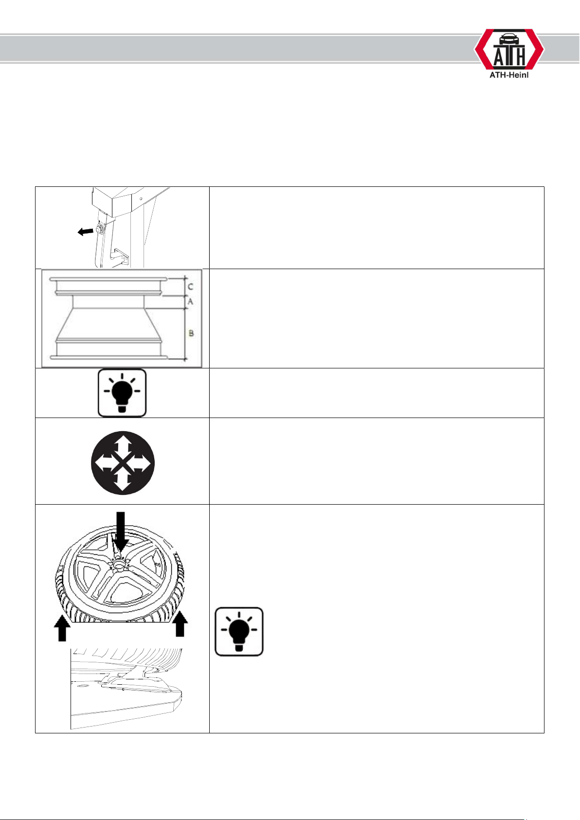
1.3.3 Clamping the wheels
Preparation
Check the following points before you mount the wheel:
- Dirt and old balancing weights must be removed from the wheel
Remove the locking device from the assembly head.
Move the assembly head into position as high and as far back as
possible and lock it again.
Now turn the assembly tower backwards.
Wheel rims with asymmetric drop-centres should be positioned so
that the narrow bead seat is facing up.
In order to prevent damage to alloy wheels when clamping, it is
recommended to only clamp these from the outside and to use
plastic protectors.
Gently press down the gear change pedal to set the required wheel
rim size (e.g. for a 20” wheel rim, set the clamping claws to 21”).
Release the pedal as soon as this has been set.
The pedal is now in the first rest position.
Position the wheel so the clamping claws only touch the tyre.
Press the wheel rim down until the rim flange touches the clamping
claws.
For hard tyres, the assembly arm can be used on the blank holder
with a cone adapter.
® Copyright ATH-Heinl GmbH & Co. KG, 2019, All rights reserved / Misprints and technical changes reserved / As of: 2019-03
Manufacturer ATH-Heinl GmbH & CO.KG
- 8 -

If you are
predominantly processing large wheels up to 24” or small 8” wheels, it is
1.3.4 Setting up the assembly head
advisable to adapt the assembly head settings to the wheel rim diameter.
The settings for the assembly head are set out in more detail in the MAINTENANCE
subsection.
Press down on the gear change pedal to clamp the wheel rim and
then release your foot. The wheel has been clamped.
Tip and/or swivel the assembly head into the working position
and release the locking device in order to bring the assembly
head up to the rim flange by hand and put it on. In order to do
so, the guide roller (3) and/or the plastic contact strip (for light
metal wheel rims) may touch the respective wheel rim contour.
When locking the assembly head, this automatically moves away
from the wheel rim in height and distance.
The settings for the automatic distance are set out in the
“Maintenance and service work” chapter.
In order to prevent light metal wheel rims from being damaged
during assembly, it is advisable to only assemble these using a
plastic protector and/or a plastic assembly head.
® Copyright ATH-Heinl GmbH & Co. KG, 2019, All rights reserved / Misprints and technical changes reserved / As of: 2019-03
Manufacturer ATH-Heinl GmbH & CO.KG
- 9 -

1.3.5 Disassembling a tyre
Turn and/or set the stretched wheel so that the
wheel valve is
In principle, the guidelines of the German Rubber Industry Trade Association
(Wirtschaftsverband der deutschen Kautschukindustrie) should be observed when
disassembling tyres.
approx. 10 cm in front of the assembly head
Press the tyre bead down against the opposite side of the
assembly head.
Then lever the tyre over the assembly head using the assembly
iron. During levering, the tyre moves into the drop-centre of the
wheel rim and facilitates simple and damage-free assembly.
In order to make it easier to lift the bead and to protect the
wheel, position the bead pusher opposite the assembly head.
Press the bead in 3, 6 and 12 o’clock position up to the first
wheel rim depression, ensuring that the tyre is not compressed
whilst doing so.
Press down the gear change pedal for the rotational motion of
the clamping plate so the rotational motion starts clockwise.
Whilst doing so, continue to hold the assembly iron on the bar of
the assembly head by pressing the iron against the assembly
head.
As soon as approx. 1/3 of the tyre bead has passed the rim
flange, there should be enough room to remove the assembly
iron.
Continue with the rotational motion until the whole tyre is above
the rim flange.
® Copyright ATH-Heinl GmbH & Co. KG, 2019, All rights reserved / Misprints and technical changes reserved / As of: 2019-03
Manufacturer ATH-Heinl GmbH & CO.KG
When working with tubular tyres, the tube should now be
removed from the tyre.
- 10 -

The tyre valve should be changed before assembly.
In order to lever the lower tyre bead, lift the tyre until it is at the
same height as the drop-centre of the wheel rim.
Then, position the assembly iron between the tyre and the
assembly head and lift the tyre directly under the assembly head.
Now lever the tyre bead over the wheel rim and commence the
rotational motion in the same way as for the upper bead.
After disassembly, press down on the gear change pedal to move
the assembly tower so it swivels back.
Then remove the tyre.
1.3.6 Assembling a tyre
In principle, the guidelines of the German Rubber Industry Trade Association
(Wirtschaftsverband der deutschen Kautschukindustrie) should be observed when
assembling tyres.
Clamp and/or set the wheel rim so that the wheel valve is
approximately 180 degrees over the assembly head.
Cover the tyre and the wheel rim in a sufficient amount of assembly
paste.
® Copyright ATH-Heinl GmbH & Co. KG, 2019, All rights reserved / Misprints and technical changes reserved / As of: 2019-03
Manufacturer ATH-Heinl GmbH & CO.KG
- 11 -

Check whether the assembly head is in the correct position for the
wheel rim. If necessary, set it up as described in the subsection
“Setting up the assembly head”.
Now place the tyre on the wheel rim at an angle so that the
assembly head does not touch any parts of the tyre when
swivelling.
Swivel the assembly tower by pressing the corresponding pedal.
Position the tyre so that the tyre bead is under the nose, but still on
the guideway of the assembly head.
When doing so, ensure that the tyre is opposite the assembly head
in the wheel rim depression.
Start the rotational movement of the clamping plate.
During the assembly process, ensure that the bead run is correct.
Failing to ensure this can cause serious damage to the tyre.
When working with tubular tyres, the tube must be positioned
correctly in the tyre. Ensure that it is positioned in the tyre such that
it will not be damaged during the remainder of the assembly
process.
® Copyright ATH-Heinl GmbH & Co. KG, 2019, All rights reserved / Misprints and technical changes reserved / As of: 2019-03
Manufacturer ATH-Heinl GmbH & CO.KG
- 12 -

When assembling the second bead, follow the exact same
procedure as for the first bead.
You must also ensure that the tyre is positioned correctly in relation
to the assembly head.
Start the rotational movement of the clamping plate.
During the assembly process, ensure that the bead run is correct.
Failing to ensure this can cause serious damage to the tyre.
In order to complete the process, release the wheel rim clamp to
remove the wheel.
® Copyright ATH-Heinl GmbH & Co. KG, 2019, All rights reserved / Misprints and technical changes reserved / As of: 2019-03
Manufacturer ATH-Heinl GmbH & CO.KG
- 13 -

1.3.7 Inflating tyres
The maximum tyre pressure may not exceed 3.5 bar.
All parts of the body should be kept away from the tyre.
During operation the noise level can reach 85 dB (A), so the operator should take
appropriate protective measures.
Ensure that the tyre has been fully lubricated.
Start the inflation process.
If the air volume of the tyre inflator is not sufficient to push the tyre
over the wheel rim, you can increase the air volume by removing the
inner valve. This must be replaced quickly afterwards.
Ensure that the tyre has been inflated to the correct pressure.
Consult the manufacturer’s specifications to establish this.
If the tyre pressure is too low, this can lead to increased wear and
decrease the service life of the tyre. The inside of the tyre can also
be damaged.
The tyre pressure must be checked once a week.
Only check the tyre pressure at normal tyre temperatures (i.e. the
vehicle has not been driven for more than an hour and not more
than 2-3 km)
® Copyright ATH-Heinl GmbH & Co. KG, 2019, All rights reserved / Misprints and technical changes reserved / As of: 2019-03
Manufacturer ATH-Heinl GmbH & CO.KG
- 14 -

1.4 Technical Data
Max. entry width (A)
4-
13 inches
Max. entry diameter (B + tyre)
960 mm
380 / 50
– 16 V/Hz
- A
Motor speed
1400 / 2800 rpm
Net weight
261 kg
Outer clamping range (B) 9-26 inches
Inner clamping range (B) 11-30 inches
Max. working range of bead breaker 4-13 inches
Max. force of bead breaker 2500 kg
Rotary plate torque 1100 Nm
Rotary plate speed 7 / 14 rpm
Power supply
Drive power
Working pressure
(220 / 50 – 16 V/Hz - A)
0.75 / 0.90 kW
(1.10 kW)
8-10 bar
(0.8-1.0 Mpa)
Noise emission < 70 dB
Gross weight 303 kg
Definition of wheel rim
A = wheel rim width (without “f” flange)
B = wheel rim diameter (without “f” flange)
f = flange
h = hump
t = drop-centre
z = centre ring
ET = offset
1 = rim centre
2 = contact surface
1 inch = 2.54 centimetres
® Copyright ATH-Heinl GmbH & Co. KG, 2019, All rights reserved / Misprints and technical changes reserved / As of: 2019-03
Manufacturer ATH-Heinl GmbH & CO.KG
- 15 -

1.5 Scale Drawing
® Copyright ATH-Heinl GmbH & Co. KG, 2019, All rights reserved / Misprints and technical changes reserved / As of: 2019-03
Manufacturer ATH-Heinl GmbH & CO.KG
- 16 -

2.0 INSTALLATION
Width
Length
Remove the top cover of the packaging and make sure that no damage has occurred
The machine must be installed by an authorised person according to the instructions.
The operating instructions (including the log) are an important part
of the machine / product.
!!!PLEASE STORE CAREFULLY!!!
The product must be checked after completion of the installation, handover, if necessary briefing and then
regularly in accordance with the applicable regulations and legal provisions in the country of operation by a
suitable and approved company or facility.
2.1 Transport & Storage Conditions
When transporting and positioning the machine, always use suitable lifting and material handling
equipment and consider the machine’s centre of gravity.
The machine should only be transported with the original packaging.
Data:
----
Height
Storage temperature
2.2 Unpacking the machine
during transport.
Remove the safety bolt to remove the machine from the pallet / rack.
Use a suitable lifting device (possibly with a stopping rope) to lower the machine from the
pallet / frame.
The packaging material used for the machine should be stored carefully.
Keep the packaging material out of the reach of children as it may be hazardous.
1.150 mm
850 mm
980 mm
-10 to +50 °C
® Copyright ATH-Heinl GmbH & Co. KG, 2019, All rights reserved / Misprints and technical changes reserved / As of: 2019-03
Manufacturer ATH-Heinl GmbH & CO.KG
- 17 -

2.3 Delivery Contents
1 Steel assembly head
2 Plastic contact strip
3 Tyre assembly iron
4 Impact anchor
Seal kit and membrane for rapid air
5
vent
6 Plastic protector for side bead breakers
7 Manual tyre inflator
8 Compressed air maintenance unit
9 16A CEE plug
® Copyright ATH-Heinl GmbH & Co. KG, 2019, All rights reserved / Misprints and technical changes reserved / As of: 2019-03
Manufacturer ATH-Heinl GmbH & CO.KG
- 18 -

2.4 Location
Sea level
< 1500 m
The machine should be kept away from flammable and explosive materials, as well as from sunlight and
intense light. The machine should be placed in a well-ventilated location.
The machine must be set up on sufficiently firm ground, if necessary, according to the minimum
requirements of the information given in the foundation plan.
In addition to the ground conditions, the guidelines and instructions of the accident prevention regulations
as well as the workplace regulations must be observed when selecting an installation site.
When assembling on floor coverings, check their load-bearing capacity. A construction expert should be
consulted for inspection when mounting on floor coverings.
The machine should only be mounted and used within closed rooms. It has no corresponding safety
features (e.g. IP protection, galvanised design, etc.).
Temperature 4-40 °C
Humidity 50% at 40 °C – 90% at 20 °C
Drawing
® Copyright ATH-Heinl GmbH & Co. KG, 2019, All rights reserved / Misprints and technical changes reserved / As of: 2019-03
Manufacturer ATH-Heinl GmbH & CO.KG
- 19 -

2.5 Fixing
General and local regulations must be observed. Therefore, these steps should only be
carried out by a trained professional.
The machine must be set up and fixed on sufficiently firm ground, if necessary, according to the minimum
requirements of the information given in the foundation plan.
The machine must be fastened at the points provided with suitable or specified fastening material.
In addition to the ground conditions, the guidelines and instructions of the accident prevention regulations
as well as the workplace regulations must be observed when selecting an installation site.
When assembling on floor coverings, check their load-bearing capacity. A construction expert should be
consulted for inspection when mounting on floor coverings.
2.6 Electrical Connection
General and local regulations must be observed. Therefore, these steps may only be
carried out by a trained professional.
Pay attention to the necessary supply line (see technical data).
The connection should be made with a 230V Schuko plug or 5-phase 16 A CEE plug (partially included).
Voltage deviations should be 0.9 - 1.1 times the nominal voltage range and the frequency deviation should
be 0.99 - 1.01 times the frequency range.
Necessary protective measures must be taken to guarantee this.
At the end of the work, the direction that the motor rotates must be checked.
2.7 Pneumatic Connection
For all pneumatic systems, a compressed air maintenance unit (partially included) must
be installed between the supply line and the system.
The air pressure of the supply line must at least correspond to the technical data.
The compressed air maintenance unit must be set correctly and checked.
The compressed air maintenance unit must be serviced at regular intervals.
The maximum or minimum pressure ensures perfect functioning without any damage.
® Copyright ATH-Heinl GmbH & Co. KG, 2019, All rights reserved / Misprints and technical changes reserved / As of: 2019-03
Manufacturer ATH-Heinl GmbH & CO.KG
- 20 -

2.8 Hydraulic Connection
These instructions are not to be viewed as assembly instructions; hints and tips are
Before the system is put into operation or operated for the first time with oil, the
following must be observed with regard to the optimal, trouble-free and almost air-free
functioning
All hydraulic lines must be connected and tightened according to the hydraulic plan and, if applicable
according to the hose designation.
All hydraulic lines and cylinders must be vented according to the hydraulic plan and, if applicable, according
to the hose designation.
In order to ensure the faultless and safe functioning of the system and the hose assemblies used, the
hydraulic fluids used must comply with the specific instructions and recommendations of the manufacturer.
Used media that do not meet the specific requirements or which have unauthorised contamination damage
the entire hydraulic system and shorten the service life of the hydraulic systems used. Warning: (system
contamination can also occur when oil is refilled)
The minimum requirement and minimum oil quantity must be checked and ensured.
2.9 Assembly
provided only for trained expert installers. Suitable clothing and personal protection must
be worn for the following work.
Incorrect installation and settings lead to exclusion of liability and warranty.
Partly pre-assembled machines must be checked, introduced and approved by a competent person before
commissioning.
Machine assembly must be carried out by a qualified and competent person.
® Copyright ATH-Heinl GmbH & Co. KG, 2019, All rights reserved / Misprints and technical changes reserved / As of: 2019-03
Manufacturer ATH-Heinl GmbH & CO.KG
- 21 -

2.9.1. Securing the machine
Tighten the nuts to the
It is recommended that the machine is secured to the floor at the four points provided using M10 anchor
screws and the corresponding dowels.
Drill holes, observing
the necessary drill depth
A and drill diameter of
the dowel manufacturer
2.10 Completion of Work
Before commissioning, check all fastening screws, electrical, pneumatic and hydraulic
lines and, if necessary, tighten these. Warning: in some cases, this must be checked at
regular intervals and tightened if necessary (note in the instructions).
Clean out the inside of
the holes
Insert the anchor bolts
into the holes until they
have reached an
appropriate depth.
torque specified by the
manufacturer
Clamping thickness B
varies depending on the
floor covering
® Copyright ATH-Heinl GmbH & Co. KG, 2019, All rights reserved / Misprints and technical changes reserved / As of: 2019-03
Manufacturer ATH-Heinl GmbH & CO.KG
- 22 -

3.0 OPERATION
Ambulance service: ____________
3.1 Operating Instructions
Company:
Place of work:
Operating Instructions
Operation:
Risks to People and the Environment
Noise danger
Danger of being caught on machine
Danger due to uncontrolled moving parts
Danger from charged dust in the brake system
Protective Measures and Rules of Conduct
Wear close-fitting clothes
Do not wear a watch, rings, chains or similar jewellery when working
Wear ear protection and safety goggles.
Longer hair should be secured by a hair net or other measure
Only use impact wrenches that don’t blow air on the wheel rim.
Clean wheels and tyres only when wet to avoid dust build-up; if possible, use wheel washing
systems.
Remove dust on the brake drums with an extraction bell with suitable industrial vacuum cleaners.
Use category U equipment for asbestos-free dusts and category K1 for asbestos-containing dusts.
(Observe current GUV regulations)
Damaged tyres must not be used.
When inflating the tyre, set up a guard to catch any flying parts. Keep people out of the danger area.
Tyre filling must be monitored and the maximum permissible assembly air pressures must not be
exceeded.
Only operate motor-driven wheel balancers with a protective hood.
For large wheels of trucks and self-driving machines:
- On machines with vertical wheels, work with heavy tyres (for example, EM tyres) must be
carried out by two people.
- For tyres with a diameter >1.4 m or a weight >200 kg, fall-protection devices must be used.
for
Tyre Servicing
Date:
Signature:
Response to faults and hazards
First Aid
Machine defects must be reported to the manufacturer immediately
Switch off the machine and secure against unauthorised restart
Damage should only be repaired by qualified personnel
Inform first aiders (see alarm/emergency plan).
Treat injuries immediately.
Enter into the accident book
Contact emergency services for serious injuries.
Emergency number:__________
Maintenance
Repair only by instructed and trained persons
Disconnect or secure the machine from the mains power supply for set-up, adjustment,
maintenance or servicing
Clean the machine after operation is ended
Annual check of the machine by an authorised and trained person
® Copyright ATH-Heinl GmbH & Co. KG, 2019, All rights reserved / Misprints and technical changes reserved / As of: 2019-03
Manufacturer ATH-Heinl GmbH & CO.KG
- 23 -

3.2 Basic Information
Independent operation of the machine may only be carried out by persons over the age of 18 who have
been trained in the operation of the machine and have demonstrated their ability to do so to the employer.
They must be expressly contracted by the employer to operate the machine. The order to operate the
machine must be given in writing.
The machine must only be used for its intended use.
Always use appropriate material during installation and operation.
Before assembly or disassembly check all components for damage.
If necessary, observe special manufacturer instructions for mounting or dismounting of vehicle-specific
work.
An important part of the guarantee / warranty is fulfilment of the maintenance plan. This includes in
particular, ensuring cleanliness, corrosion protection, checks and repairing damages immediately if
required.
During operation attention should always be paid to hazards. As soon as dangers occur, switch off the
machine immediately, remove the mains plug and disconnect the air supply.
Then contact your dealer.
All warning labels must always be easy to read. If damaged, they must be replaced immediately.
Pay attention to possible shearing points around the machine.
During operation, the noise can reach 85dB (A), so the operator should take appropriate
protective measures.
Moving parts of the machine can catch loose clothing, long hair or jewellery.
® Copyright ATH-Heinl GmbH & Co. KG, 2019, All rights reserved / Misprints and technical changes reserved / As of: 2019-03
Manufacturer ATH-Heinl GmbH & CO.KG
- 24 -

4.0 MAINTENANCE
The user must maintain the machine regularly to ensure safe operation.
Repair work may only be carried out by authorised service partners or after customer consultation with the
manufacturer.
Before maintenance and repair work:
- The machine must be disconnected from ALL supply networks
- Pull main switch out of mains plug, if necessary, discharge compressed air from system
- Appropriate measures must be taken against a restart
Work on electrical elements or on the supply line may only be carried out by experts or
electricians.
4.1 Consumables for installation, maintenance and servicing
Hydraulic Oil
General minimum requirement:
Eni PRECIS HVLP-D Item No. 00066018
Summer (15° to 45°): HVLP-D 46 (e.g.: Eni PRECIS HVLP-D)
Winter (under 10°): HVLP-D 32 (e.g.: Eni PRECIS HVLP-D)
Minimum requirement especially for 2-post lifts:
Eni PRECIS HVLP-D Item No. 00067218
Summer (15° to 45°): HVLP-D 32 (e.g.: Eni PRECIS HVLP-D)
Winter (under 10°): HVLP-D 22 (e.g.: Eni PRECIS HVLP-D)
Preservative for ropes, welds, screws, corners, edges and cavities.
Minimum requirement:
Petec spray translucent - 500 ml Item No. 73550 / Petec wall inlet translucent - 1000 ml Item No.
73510
Petec UBS pistol Item No. 98507
Slideway lubricant
Minimum requirement:
STORER WHS 2002 White EP high performance grease. Item No. KPF1-2K-20
Lubricant for bushes, chains, rollers & moving parts
Minimum requirement:
White ultra lube, 500 ml aerosol. Item No. 34403 – WUL – White Ultra Lube
Floor anchor
Minimum requirement for lifting platforms:
Fischer FIS A M 16 x 200 galvanised in combination with Fischer Superbond reaction cartridge
Minimum requirement for passenger car and passenger car/truck balancing machine:
Impact anchor M8 x 100
Minimum requirement for truck mounting machine:
Impact anchor M12 x 100
Compressed air system
® Copyright ATH-Heinl GmbH & Co. KG, 2019, All rights reserved / Misprints and technical changes reserved / As of: 2019-03
Manufacturer ATH-Heinl GmbH & CO.KG
- 25 -

Minimum requirement:
PROMAT chemicals special compressed air oil Item No.: 4000355209
Cleaning
Minimum requirement:
Caramba intensive brake cleaner acetone-free
Care and protection of metals, painted or powder-coated surfaces
Minimum requirement:
Petec spray translucent - 500 ml Item No. 73550
Petec wall inlet translucent - 1000 ml Item No. 73510
Petec UBS pistol Item No. 98507
Care and protection of metals, painted or powder-coated surfaces in the tread area and plastic
parts
Minimum requirement:
Valet Pro Classic Protectant Plastic Sealant 500 ml
4.2 Safety Regulations for Oil
Always observe the legal requirements or regulations for handling used oil.
Always dispose of used oil through a certified organisation.
In the case of leaks, oil must be collected immediately with binders or trays so that it cannot penetrate into
the soil.
Avoid any skin contact with the oil.
Do not allow oil vapours to escape into the atmosphere.
Oil is a combustible medium. Pay attention to possible hazards.
Wear oil-resistant protective clothing, such as gloves, goggles, protective clothing, etc.
® Copyright ATH-Heinl GmbH & Co. KG, 2019, All rights reserved / Misprints and technical changes reserved / As of: 2019-03
Manufacturer ATH-Heinl GmbH & CO.KG
- 26 -

months
months
Check of ALL safety
-
relevant parts
X
Cleaning
X
Check or restore rust damage
X
Check wear parts
X
Check fluids (level, wear, contamination, quality)
X
Check motor and transmission for function and wear
X
Check welds and construction
X
Interval
4.3 Notes
Regardless of the level of dirt, the machine must be maintained, cleaned and serviced at
regular intervals.
The machine should then be treated with a care product (such as oil or wax spray).
Do not use cleaning agents that are harmful to the skin.
IF THE ABOVEMENTIONED POINTS ARE NOT FULFILLED, THE WARRANTY CLAIM IS
EXCLUDED
4.4 Maintenance or Service Plan
Weekly
Every 3
Monthly
Every 6
Immediately
Check or restore surface protection X
Check for leaks in the hydraulic system X
Check or restore surface protection or corrosion protection X
Check or restore damage to the paint and components X
Check or treat cavities and non-painted areas X
Check for leaks in the pneumatic system X
Control the tightness of screws X
Check, lubricate & adjust bearing slack X
Check and lubricate sliding surfaces X
Remove any dirt inside X
Clean and check electrical components X
Visual inspection (according to inspection plan) X
® Copyright ATH-Heinl GmbH & Co. KG, 2019, All rights reserved / Misprints and technical changes reserved / As of: 2019-03
Manufacturer ATH-Heinl GmbH & CO.KG
- 27 -

4.5 Troubleshooting / Error Display and Solutions
Air pressure / hydraulic
Assembly tool has too
Wear of seals and/or bushings
Air pressure / hydraulic
Check rotary reversing switch /
Pressing points and/or
Study the operating instructions
Symptoms Cause
Solution
Machine has no / not
enough power
much slack / loosens again
and again
Rim cannot be clamped on
the wheel
Wheel does not rotate /
only rotates in one
direction
kinks on the tyre
Product shows (heavy) rust
damage
ALWAYS USE ORIGINAL PARTS AND ACCESSORIES
® Copyright ATH-Heinl GmbH & Co. KG, 2019, All rights reserved / Misprints and technical changes reserved / As of: 2019-03
pressure too low
Increase air pressure / check oil level
2-phase running of motor Check electrical connection
V-belt not tightened enough Retighten V-belt
Have wear parts replaced by a KD
technician
Defective pedal / rocker switch Replace components
Pneumatic/hydraulic cylinder
jams or leaks
pressure too low
Replace cylinder or replace seals
Increase air pressure / check oil level
Valve block does not respond Check control
Pedal / joystick does not
respond
Replace components
control
Check electrical connection
Assembly tool used incorrectly
again step by step
Damage or lack of corrosion
protection, possibly
maintenance
Remove rust, clean and restore
surface.
Manufacturer ATH-Heinl GmbH & CO.KG
- 28 -

4.6 Maintenance and Service Instructions
COMPRESSED AIR MAINTENANCE UNIT
B
4
3
All maintenance and service work should be carried out at least according to the
maintenance schedule
(Partial stock if necessary for the activity)
SETTING THE WORKING PRESSURE:
Check the working pressure displayed by the
manometer (1). This must correspond to the
technical data.
The working pressure can be adjusted with a
pressure regulator (A).
Pull the pressure regulator upwards to make
adjustments.
Turn the knob clockwise to increase the pressure in
the machine, turn it counter clockwise to decrease.
OILER
Check the oil level in the oil reservoir (3).
Remove the oil reservoir.
Now refill the tank with a pneumatic oil with a
viscosity of SAE20.
Check the injection quantity of the oil through
the viewing glass (4).
Generally, the screw must be closed completely
in a clockwise direction and then opened again
about ¼ to ½ turn by turning it counter
clockwise.
WATER SEPARATOR
Check the water level in the separator (2).
Water is drained when the valve (B) is opened.
C
A
1
2
® Copyright ATH-Heinl GmbH & Co. KG, 2019, All rights reserved / Misprints and technical changes reserved / As of: 2019-03
Manufacturer ATH-Heinl GmbH & CO.KG
- 29 -

V-BELT TENSIONING
A
The machine contains a motor (1) which
drives the worm gear (3) using a V-belt (2).
In order to tension, you must loosen the
motor fixing screws.
Next, loosen the counter nut (B)
The V-belt is tensioned by turning the
screw (A).
o When pressed down (in the centre),
the V-belt should give by a
maximum of 8 mm.
The counter nut (B) and all motor fixing
screws must be tightened for final fixing.
The final stage is to reassemble the cover.
PNEUMATIC LOCKING OF THE MOUNTING HEAD
The force and/or tension of the cylinder is
set by tightening and/or loosening the
screw (B).
The automatic distance to the rim is set by
tightening and/or loosening the nut (A).
3
2
1
B
SWIVEL SPEED
The swivel speed to the front and/or rear can
be set by opening and/or closing the valves
(A+B).
® Copyright ATH-Heinl GmbH & Co. KG, 2019, All rights reserved / Misprints and technical changes reserved / As of: 2019-03
Manufacturer ATH-Heinl GmbH & CO.KG
- 30 -

CLEANING THE VALVE BLOCK
Separate the air pipes (H) from the valve block
(V).
Clean the valve block (V) using compressed air.
The valve block may need to be replaced.
Clean the silencers (S). If these are damaged,
they must be replaced.
SETTING THE MOUNTING HEAD
Loosen the fixing screw (1) on the mounting
head
The angle of the mounting head to the rim can
be set by tightening and/or loosening both
grub screws (2)
The bead guide (4) projects approx. 6-7 mm
over the rim flange. The approach roller (3)
contacts the rim flange.
After setting, ensure that both grub screws (2)
and the fixing screw (1) are secured again.
CHECKING AND REFILLING THE GEAR OIL
Turn the clamping plate to a position from
which it is easy to access the oil filler neck
Now remove the protective cover
Insert a flexible and transparent hose into the
opening and stop when the hose contacts the
base of the gear unit.
Now, hold the end of the hose shut so that no
more air can get in.
Next, remove the hose. The oil level must be at
least 25 mm.
If necessary, refill with the required amount of
oil.
3
® Copyright ATH-Heinl GmbH & Co. KG, 2019, All rights reserved / Misprints and technical changes reserved / As of: 2019-03
Manufacturer ATH-Heinl GmbH & CO.KG
- 31 -

4.7 Disposal
Remove the air and power supply.
Remove all non-metallic substances and store them in accordance with local regulations.
Remove the oil from the machine and store it in accordance with local regulations.
Recycle all metallic substances.
The machine contains some substances that can pollute the environment and cause harm
to the human body if not handled correctly.
® Copyright ATH-Heinl GmbH & Co. KG, 2019, All rights reserved / Misprints and technical changes reserved / As of: 2019-03
Manufacturer ATH-Heinl GmbH & CO.KG
- 32 -

5.0 EG-/EU-KONFORMITÄTSERKLÄRUNG / EC-/EU-DECLARATION OF CONFORMITY
Hiermit erklären wir, dass die nachfolgend bezeichnete Maschine in der von
uns in Verkehr gebrachten Ausführung den einschlägigen,
CCQS UK Ltd.
TF-C-0612-15-63-01-2A
CE-C-0612-15-63-01-2A
DURCH UMBAUTEN UND/ODER VERÄNDERUNGEN AN DER MASCHINE WIRD DIE CE
-
PRÜFUNG AUSSER KRAFT GESETZT UND
gemäß Maschinenrichtlinie 2006/42/EG, Anhang II 1A, EMV-Richtlinie 2014/30/EU, Anh. IV
In accordance to Machine Directive 2006/42/EG, Appendix II 1A, EMC Directive 2014/30/EU, App. IV
Seriennummer
Serial number
ATH-Heinl GmbH &Co. KG
Firmenbezeichnung und vollständige Anschrift des Herstellers
Business name and full address of the manufacturer
DE – 92278 Illschwang
Name und Anschrift des Dokumentations-Bevollmächtigten
Name and address of the Technical Files authorized
representative
ATH-Heinl GmbH &Co. KG
DE – 92278 Illschwang
Gewerbepark 9
Gewerbepark 9
grundlegenden Sicherheits- und Gesundheitsanforderungen der EG-Richtlinie 2006/42/EG sowie den unten aufgeführten
We herewith declare
fundamental Safety and Health regulations of the of Directive 2000/60/EC and the harmonized standards listed below
Beschreibung der Maschine
Descriptions of the machine
that that the machine described below, as a result have been brought on to the general market comply with the relevant
Harmonisierungsrechtsvorschriften entspricht.
Reifen-Montiermaschine
Tyre changer
Typbezeichnung
Model name
ATH M72
Der oben beschriebene Gegenstand der Erklärung erfüllt die
folgenden einschlägigen Harmonisierungs-Rechtsvorschriften der
Union
The object of the declaration described above meets the
(Maschinen-Richtlinie / Machine-Directive)
2006/42/EC
following applicable Community harmonisation legislation
Folgende harmonisierten Normen und Vorschriften wurden
eingehalten
The following harmonized standards and regulations are applied
EN ISO 12100:2010
EN 60204-1:2006 + A1:2009
Prüfinstitut
Institute of Quality
Level 7, Westgate House, Westgate Road,
London W5 1YY
ENGLAND
Referenznummer der technischen Daten
Reference number for the technical data
Nummer des Zertifikats
Number of the certificate
ATH-Heinl GmbH &Co. KG
Gewerbepark 9
DE – 92278 Illschwang
March 2016
.
BY MODIFICATION AND / OR CHANGES TO THE MACHINE, THE CE EXAMINATION IS EXCLUDED WITHOUT LIMITATION AND A
® Copyright ATH-Heinl GmbH & Co. KG, 2019, All rights reserved / Misprints and technical changes reserved / As of: 2019-03
EINE HAFTUNG AUSGESCHLOSSEN.
LIABILITY SHALL BE EXCLUDED.
Manufacturer ATH-Heinl GmbH & CO.KG
- 33 -
Hans Heinl
(Geschäftsführer /
General Manager
)

6.0 APPENDIX
6.1 Pneumatic circuit diagram
® Copyright ATH-Heinl GmbH & Co. KG, 2019, All rights reserved / Misprints and technical changes reserved / As of: 2019-03
Manufacturer ATH-Heinl GmbH & CO.KG
- 34 -

6.2 Electric circuit diagram
® Copyright ATH-Heinl GmbH & Co. KG, 2019, All rights reserved / Misprints and technical changes reserved / As of: 2019-03
Manufacturer ATH-Heinl GmbH & CO.KG
- 35 -

6.3 Hydraulic circuit diagram
Not relevant!
® Copyright ATH-Heinl GmbH & Co. KG, 2019, All rights reserved / Misprints and technical changes reserved / As of: 2019-03
Manufacturer ATH-Heinl GmbH & CO.KG
- 36 -

7.0 WARRANTY CARD
Dealer address:
Company (or customer number):
Contact partner:
Street:
Postcode & town:
Tel. & Fax:
Email:
Manufacturer & model: Serial number:
Customer address:
Company (or customer number):
Contact partner:
Street:
Postcode & town:
Tel. & Fax:
Email:
Year of construction:
Reference number:
Message description:
Description of required spare parts:
Spare part: Item number: Amount:
IMPORTANT:
Damage resulting from improper handling, lack of maintenance or mechanical damage is not covered by
the warranty. For systems that have not been installed by an ATH approved installer, the warranty is
limited to the provision of the necessary spare parts.
Transport damages:
Visible defect (visible transport damage, note on freight forwarder delivery note, immediately send
copy of the delivery note and photos to ATH-Heinl)
Hidden defect (transport damage is only detected when unpacking the goods, send damage report
with pictures to ATH-Heinl within 24 hours)
Place & Date Signature & Stamp
® Copyright ATH-Heinl GmbH & Co. KG, 2019, All rights reserved / Misprints and technical changes reserved / As of: 2019-03
Manufacturer ATH-Heinl GmbH & CO.KG
- 37 -

7.1 Scope of the Product Warranty
Five years for the devices structure
Power supplies, hydraulic cylinders and all other wear components such as turntables, rubber plates,
ropes, chains, valves, switches, etc., are limited to one year under normal circumstances/use under
warranty conditions.
The warranty does not extend to:
Defects caused by normal wear and tear, misuse, transport damage, improper installation, tension or
lack of required maintenance.
Damage caused by neglect or failure to follow the instructions in this manual and/or other
accompanying instructions.
Normal wear and tear on parts requiring service to keep the product in safe working condition.
Any component that has been damaged during transport.
Other components that have not been explicitly listed but are considered to be general consumables.
Water damage caused by e.g. rain, excessive humidity, corrosive environments or other contaminants.
Blemishes that do not affect function.
WARRANTY IS NOT VALID,
IF THE WARRANTY CARD WAS NOT SENT TO ATH-HEINL.
Damage and malfunctions caused by non-compliance with maintenance and adjustment work (according to
operating instructions and/or training), faulty electrical connections (rotating field, rated voltage,
protection) or improper use (overload, outdoor installation, technical changes) are excluded from the
warranty!
® Copyright ATH-Heinl GmbH & Co. KG, 2019, All rights reserved / Misprints and technical changes reserved / As of: 2019-03
Manufacturer ATH-Heinl GmbH & CO.KG
- 38 -

8.0 INSPECTION LOG
This inspection manual (including log) is an important part
of the operating instructions and product.
!!!PLEASE STORE CAREFULLY!!!
Check
The product must be checked after completion of the installation, handover, if necessary briefing and then
regularly in accordance with the applicable regulations and legal provisions in the country of operation by a
suitable and approved company or facility.
In the case of changes or extensions to the product type, an additional inspection book must be
maintained and accepted.
Scope of Inspection
In addition to perfect function, cleanliness and maintenance requirements, it is vital that the safety-relevant
components of the entire system are checked.
Technical Data
- Please refer to the enclosed operating instructions.
Nameplate
- Make a note of all the data below
- Manufacturer & type of mounting materials used:
® Copyright ATH-Heinl GmbH & Co. KG, 2019, All rights reserved / Misprints and technical changes reserved / As of: 2019-03
Manufacturer ATH-Heinl GmbH & CO.KG
- 39 -

8.1 Installation and Handover Log
Site: Device / system:
Company: Manufacturer:
Street: Type / model:
Town: Serial no.:
Country: Year of
construction:
Responsible retailer:
The above product has been assembled, checked for function and safety and put into operation. Installation was
carried out by:
the operator the technical expert
The operator confirms that the product type has been set up correctly, that he/she has read and understood all
information contained in these
operating instructions and the log, and that he/she keeps this documentation accessible to the instructed operator at
all times.
The operator confirms that after installation and commissioning by a person trained by the
manufacturer or an authorised dealer (expert), instruction in the function, handling, safety-relevant specifications,
maintenance and care of the machine has taken place, documents, information and specifications of the machine
have been provided and the product is working properly.
IMPORTANT NOTES:
IF THE ABOVEMENTIONED POINTS ARE NOT FULFILLED, THE WARRANTY CLAIM IS EXCLUDED:
The warranty is only valid in conjunction with compliance and evidence of proper assembly, handover, and if
necessary training, as well as yearly maintenance carried out by an expert authorised by the manufacturer. The
interval between services must not exceed 12 months. In case of non-standard use or multi-shift or seasonal use, a
bi-annual inspection and maintenance must be arranged.
Warranty claims are only recognised if all points in the log and operating instructions have been met, the claim is
asserted immediately after detection and this log is sent to the manufacturer along with the maintenance
and service logs.
Further specific information about the warranty, such as scope, requirements and specifications, are described in the
operating instructions and must be observed.
Damages and complaints caused by improper handling; failure to maintain and service; use of unsuitable or
unspecified assembly, operating, maintenance or service products; mechanical damage; intervening in the unit
without consultation or by an unauthorised expert are excluded from the warranty. For systems that have not been
installed by an authorised expert, the warranty is limited by agreement of the manufacturer to the provision of the
necessary spare parts.
Expert name and company stamp
Date and expert signature
if necessary, number and name of retailer
Operator name and company stamp
Date and operator signature
® Copyright ATH-Heinl GmbH & Co. KG, 2019, All rights reserved / Misprints and technical changes reserved / As of: 2019-03
Manufacturer ATH-Heinl GmbH & CO.KG
- 40 -

8.2 Inspection Plan
Operating
instructions
Safety label
Condition of concrete flor (cracks)
Condition / general condition
Condition / lubrication
Condition / aggregate
Condition / cylinder
Condition / valve
Condition / hydraulic lines
Condition / bolts and bearings
Condition / consumables
Condition / electrical safety device
Condition / hydraulic safety device
Inspection
sticker issued
Nameplate
Quick reference guide
Operation label
Other labels
Construction (deformation, cracks)
Fixing dowels and stability
Condition / cleanliness
Condition / care and sealing
Condition / liquids
Condition / drive
Condition / motor
Condition / transmission
Condition / electrical control
Condition / electric buttons
Condition / electric switches
Condition / electric lines
Condition / hydraulic screws
Condition / pneumatic lines
Condition / pneumatic screws
Condition / tightness
Condition / covers
Condition / functions under load
Condition / safety-relevant components
Condition / pneumatic safety device
Condition / mechanical safety device
Condition / functions under load
® Copyright ATH-Heinl GmbH & Co. KG, 2019, All rights reserved / Misprints and technical changes reserved / As of: 2019-03
Manufacturer ATH-Heinl GmbH & CO.KG
- 41 -

8.3 Visual inspection (authorised expert)
(Place, date)
(Technical expert signature)
(Name of technical expert)
(Title)
(Address)
(Employed at)
Operator (company stamp, date, signature)
Inspection Certificate
relating to a regular / extraordinary inspection / audit *)
The device has undergone a readiness test.
No / the following *) defects were found:
_________________________________________________________________________________
_________________________________________________________________________________
_________________________________________________________________________________
_________________________________________________________________________________
_________________________________________________________________________________
Inspection contents: functional and visual inspection according to specifications
Pending partial inspection:
_________________________________________________________________________________
_________________________________________________________________________________
There were no *) concerns arising from commissioning, an audit is not *) required.
Confirmation of acceptance:
Faults noted **) ________________________________________________________
Faults remedied **) ____________________________________________________________________
*) Delete if not applicable
**) Confirmation of operator or a representative with date and signature
® Copyright ATH-Heinl GmbH & Co. KG, 2019, All rights reserved / Misprints and technical changes reserved / As of: 2019-03
Manufacturer ATH-Heinl GmbH & CO.KG
- 42 -

Visual inspection (authorised expert)
(Place, date)
(Technical expert signature)
(Name of technical expert)
(Title)
(Address)
(Employed at)
Operator (company stamp, date, signature)
Inspection Certificate
relating to a regular / extraordinary inspection / audit *)
The device has undergone a readiness test.
No / the following *) defects were found:
_________________________________________________________________________________
_________________________________________________________________________________
_________________________________________________________________________________
_________________________________________________________________________________
_________________________________________________________________________________
Inspection contents: functional and visual inspection according to specifications
Pending partial inspection:
_________________________________________________________________________________
_________________________________________________________________________________
There were no *) concerns arising from commissioning, an audit is not *) required.
Confirmation of acceptance:
Faults noted **) ________________________________________________________
Faults remedied **) ____________________________________________________________________
*) Delete if not applicable
**) Confirmation of operator or a representative with date and signature
® Copyright ATH-Heinl GmbH & Co. KG, 2019, All rights reserved / Misprints and technical changes reserved / As of: 2019-03
Manufacturer ATH-Heinl GmbH & CO.KG
- 43 -

Visual inspection (authorised expert)
(Place, date)
(Technical expert signature)
(Name of technical expert)
(Title)
(Address)
(Employed at)
Operator (company stamp, date, signature)
Inspection Certificate
relating to a regular / extraordinary inspection / audit *)
The device has undergone a readiness test.
No / the following *) defects were found:
_________________________________________________________________________________
_________________________________________________________________________________
_________________________________________________________________________________
_________________________________________________________________________________
_________________________________________________________________________________
Inspection contents: functional and visual inspection according to specifications
Pending partial inspection:
_________________________________________________________________________________
_________________________________________________________________________________
There were no *) concerns arising from commissioning, an audit is not *) required.
Confirmation of acceptance:
Faults noted **) ________________________________________________________
Faults remedied **) ____________________________________________________________________
*) Delete if not applicable
**) Confirmation of operator or a representative with date and signature
® Copyright ATH-Heinl GmbH & Co. KG, 2019, All rights reserved / Misprints and technical changes reserved / As of: 2019-03
Manufacturer ATH-Heinl GmbH & CO.KG
- 44 -

Visual inspection (authorised expert)
(Place, date)
(Technical expert signature)
(Name of technical expert)
(Title)
(Address)
(Employed at)
Operator (company stamp, date, signature)
Inspection Certificate
relating to a regular / extraordinary inspection / audit *)
The device has undergone a readiness test.
No / the following *) defects were found:
_________________________________________________________________________________
_________________________________________________________________________________
_________________________________________________________________________________
_________________________________________________________________________________
_________________________________________________________________________________
Inspection contents: functional and visual inspection according to specifications
Pending partial inspection:
_________________________________________________________________________________
_________________________________________________________________________________
There were no *) concerns arising from commissioning, an audit is not *) required.
Confirmation of acceptance:
Faults noted **) ________________________________________________________
Faults remedied **) ____________________________________________________________________
*) Delete if not applicable
**) Confirmation of operator or a representative with date and signature
® Copyright ATH-Heinl GmbH & Co. KG, 2019, All rights reserved / Misprints and technical changes reserved / As of: 2019-03
Manufacturer ATH-Heinl GmbH & CO.KG
- 45 -

9.0 SPARE PART BOOK
® Copyright ATH-Heinl GmbH & Co. KG, 2019, All rights reserved / Misprints and technical changes reserved / As of: 2019-03
Manufacturer ATH-Heinl GmbH & CO.KG
- 46 -

Gehäuse / Chassis
® Copyright ATH-Heinl GmbH & Co. KG, 2019, All rights reserved / Misprints and technical changes reserved / As of: 2019-03
Manufacturer ATH-Heinl GmbH & CO.KG
- 47 -

Description
Cross recessed pan head screw
# ATH # Referenz Beschreibung
´01-01
´01-02 030201780
´01-03
´01-04
RAB0011 0530101328 Seitliche Abdeckung Side Cover
Kreuzschlitz Flachkopf Schraube
M6x20
030206004
020602021 Kabelverschraubung M20 lock loop M20
Selbstschneidende Schraube
M5.5x16
´01-05 020402021 Stromkabel 3x1.5mm²x3.5m
´01-06
´01-07
´01-08
´01-09 RKA0001 020601119
´01-10
020101018 Kabelhalter Ø16 Cable Holder Ø16
RAB0014 0530101329 Kunststoffabdeckung Front cover
RVS0001 020101007 Gummistopfen Tire Changer Body Plug
Werkzeugschale Pentagon,
Schwarz
RAB0013 0530101325 Vordere Abdeckung Chassis front board
cross recessed brazier head screw
M6x20
STS M5.5x16
Europe plug power line
3x1.5mm²x3.5m
Tool tray Pentagon, black
´01-11
´01-12 030501005 Unterlegscheibe Ø8
´01-13
´01-14 030201408 Kreuzschlitz-Schraube M6x30
´01-15 RMB0003 0530103006
´01-16
´01-17
´01-18
030201403 Zylinderkopf-Schraube M6x12
030501004 Unterlegscheibe Ø6 Washer Ø6
Metall-Buchse Metal Bushing
RMB0004 0530103007 Exzenter-Buchse Eccentric Bushing
030502007 Federscheibe Ø12 Washer Ø12
030201113 Zylinderkopf-Schraube M12x35 SHCS M12x35
M6x12
cross recessed brazier head screw
Ø8
Cross recessed pan head screw
M6x30
´01-19 RGP0002 020101037 Gummischutz Abdrücker Wheel Support Pad
´01-20 RBB0001 0530101386
´01-21 0530101387
´01-22
´01-23
´01-24
´01-25
030201333 Schraube M4x8 Washer M4x8
530203054 Haken Breaker Arm Pin
RZF0001 020702003 Rückzugfeder Bead breaker Return Spring
RGP0003 020101005 Gummi fuß Plastic Foot Pad
Stift SHCS
Umlenkblech Washer
´01-26 030502004 Federscheibe Ø6 Soap Bucket Retaining Ring Ø6
´01-27 030201044 Zylinderkopf-Schraube M6x20 SHCS M6x20
´01-28 RFB0007 0530101662
´01-29
´01-30
´01-31
´01-32
030101023 Bolzen M6x20 Washer M6x20
030101023 Sechskant-Schraube M6x20 SHCS M6x20
030301053 Unterlegscheibe M6 Washer M6
0530102876 Halterung Lock nut
Halterung Washer
´01-35 030301137 Mutter Nut
´01-36 030301003 Mutter M10 1hex nut M10
´01-37 030502006 Federscheibe Ø10 Washer Ø10
´01-38
030501006 Unterlegscheibe Ø10 Washer Ø10
® Copyright ATH-Heinl GmbH & Co. KG, 2019, All rights reserved / Misprints and technical changes reserved / As of: 2019-03
Manufacturer ATH-Heinl GmbH & CO.KG
- 48 -

´01-39 030501106 Unterlegscheibe Ø10 Washer Ø10
Druckluftwartungseinheit
DFC
-
Air regulator assembly
DFC
-
´01-40
´01-41
´01-42
030201041 Schraube M6x10 SHCS M6x10
030101111 Bolzen M10x160 hex bolt M10x160
RBS0001 0530103021 Drehteller Pass ring Turntable retaining ring
´01-43 030201433 Schraube M16x40 Flat Socket Cap Screw M16x40
´01-44 030101113 Bolzen M10x170 hex bolt M10x170
´01-45 030903035 Splint Ø3.2x25 Cotter Ø3.2x25
´01-46 RBS0002 0530102231
´01-47
´01-48
´01-49
RAN0006 020601099 Gummi Anschlag Rubber Shock Bushing
RDN0001 020101040 Gummi Distanzstück Tilt Tower Rubber Spacer
RBS0003 0530102232 Aufnahmeachse oben Zylinder Tilt Tower Cylinder Upper Pin
´01-50 REN0001 0530117022
´01-51 RAN0007 0530117021
Aufnahmeachse unten Zylinder Tilt Tower Cylinder Lower Pin
Beilagscheibe Washer
Verbindungsstück Zylinder Tilt Cylinder Connector
´01-52 030101154 Zylinderkopfschraube M12x30 SHCS M12x30
´01-54 030501007 Unterlegscheibe Ø12 Washer Ø12
´01-55
´01-56
´01-57
030501004 Unterlegscheibe Ø6 Washer Ø6
030201043 Zylinderkopfschraube M6x16 SHCS M6x16
030101162 Sechskantschraube M12x70 hex bolt M12x70
´01-59 030501007 Unterlegscheibe Ø12 Washer Ø12
´01-60 030501004 Unterlegscheibe Ø6 Washer Ø6
´01-61 030201043 Zylinderkopfschraube M6x16 SHCS M6x16
´01-62 RKA0002 020601197 Kunststoffabdeckung Outer Tilt Tower Cover
´01-63
´01-64
´01-65
030101117 Sechskantschraube M10x190 hex bolt M10x190
RGE0001 0520101620 Chassis komplett new type body K
030502002 Unterlegscheibe Ø4 washer Ø4
´01-66 030201004 Zylinderkopfschraube M4x12 SHCS M4x12
´01-67 030501002 Unterlegscheibe Ø4 washer Ø4
´01-68 RBW0001 0530108001
Halterung Air/Oil Regulator Bracket
´01-69
RWE8000 0520108310
´01-70 RWR8000 020201006 Druckregler Atomized lubricator
´01-71 020203002
´01-72
´01-73
020601038 Fettbehälter Grease container
020203025 Anschluss Ø10 - G1/4“ Fittings Ø10 - G1/4“
´01-74 RWO8001 020201004 Öl Behälter Oil cup
´01-75 RWF8001 020201005 Wasserbehälter Water cup
´01-76 RMA8000 020201012 Manometer Barometer
´01-77 RWO8002 020201011 Zerstäubungsöler Atomized lubricator
´01-78
020203013 Anschluss Ø8 - G1/4“ Lock fittings Ø8 - G1/4“
® Copyright ATH-Heinl GmbH & Co. KG, 2019, All rights reserved / Misprints and technical changes reserved / As of: 2019-03
2010A(G)
T-Verbindungsstück G1/4“ - Ø8 -
G1/4“
Manufacturer ATH-Heinl GmbH & CO.KG
- 49 -
2010A(G)
Tee G1/4“- Ø8 - G1/4“

Pedaleinheit / Pedal unit
® Copyright ATH-Heinl GmbH & Co. KG, 2019, All rights reserved / Misprints and technical changes reserved / As of: 2019-03
Manufacturer ATH-Heinl GmbH & CO.KG
- 50 -

RAV0001
RFA0002
RFD0695
RPA0003
RPG0001
RFP0700
#
´02-01
´02-02
´02-03
´02-04
´02-05
´02-06
´02-07
´02-08
´02-09
´02-10
´02-11
´02-12
´02-13
´02-14
´02-15
´02-16
´02-17
´02-18
´02-19
´02-20
´02-21
´02-22
´02-23
´02-24
´02-25
´02-26
´02-27
´02-28
´02-29
´02-30
´02-31
´02-32
´02-33
´02-34
´02-35
´02-36
´02-37
´02-38
´02-39
´02-40
´02-41
´02-42
´02-43
´02-44
´02-45
ATH #
RPE2000
RSD0736
RVB0972
RKH1207
RDR0936
RVS8001
Referenz Beschreibung
0520106120 Pedaleinheit Foot Pedal Assembly
020203030 Anschluss G1/8“ - Ø8 fitting G1/8“- Ø8
020203023 Einstellbarer Schalldämpfer G1/8“ Adjustable Silencer G1/8“
0520129250 Luftventil Schwenkzylinder Tilt Back Air Valve
020601050 Distanzhülse Luftventil Air valve O-ring spacer
020501013 O-Ring Ø17x4 O-ring Ø17x4
0530106049 Kolbenstange Luftventil Abdrücker
Description
Bead Breaker Cylinder Valve
Rod
020601078 Luftventil Abdeckkappe Air Valve End Cap
030201042 Zylinderkopfschraube M6x12 SHCS M6x12
030502004 Unterlegscheibe Ø6 washer Ø6
RAS0002
RAS0002
RFP0699
RPE2001
RPA0001
RPA0002
030201458 Kreuzschlitz-Flachkopf-Schraube M4x10 FHPS M4x10
030301002 Nut M8 Nut M8
0530106010 Verbindungsachse Pedal Foot Pedal Link
030904094 Stift Ø4x18 Spring Pin Ø4x18
0530106033 Verbindungsstück Ventil Air Valve Connecting Link
030301053 Sicherungsmutter M6 lock nut M6
0530106037 Fuß pedal rechts Foot Pedal (Right)
030604005 Sprengring Ø12 snap ring Ø12
0530106030 Grundplatte Base board
030502005 Unterlegscheibe Ø8 washer Ø8
030101042 Sechskant-Schraube M8x16 hex bolt M8x16
0530106035 Achse Fuß pedal Foot pedal shaft
0530106045 Einstellplatte dünn Foot Pedal Adjust Pad
030301002 Mutter M8 hex nut M8
030201069 Zylinderkopfschraube M8x50 SHCS M8x50
0530106036 Torsionsfeder Aufnahme Torsion spring bracket
020703005 Torsionsfeder Foot pedal torsion spring
0530106043 Anschlag Fuß Pedal Foot Pedal Limit Rod
020101017 Gummiplatte Foot Pedal Rubber Insert;
0530106034 Fuß pedal links Foot Pedal (Left)
030501104 Unterlegscheibe Ø6 washer Ø6
RGD0980
RKF0729
RHS0992
RWS0972
RWS0974
RZF0760
RVB0974
® Copyright ATH-Heinl GmbH & Co. KG, 2019, All rights reserved / Misprints and technical changes reserved / As of: 2019-03
030903035 Splint 3.2x25 cotter3.2x25
0530106038 Schaltstange Directional switch cam linkage
020601030 Schaltwinkel Turntable Direction Switch Cam
030201042 Zylinderkopfschraube M6x12 SHCS M6x12
030502004 Federscheibe Ø6 spring washer Ø6
030501004 Unterlegscheibe Ø6 washer Ø6
0530106001 Aufnahme Drehwendeschalter Directional Switch Bracket
020401012 Drehwendeschalter Directional Switch
020601031 Abdeckung Drehwendeschalter Directional Switch Cover
030201052 Zylinderkopfschraube M6x55 SHCS M6x55
020702008 Feder Foot Pedal Return Spring
020203011 Anschluss G1/8“ - Ø8 fitting G1/8“- Ø8
0520129260 Luftventil Spannzylinder Jaw Clamp Air Valve
020203013 Anschluss G1/4“ - Ø8 fitting G1/4“- Ø8
Manufacturer ATH-Heinl GmbH & CO.KG
- 51 -

Foot Pedal Cam Leaf Spring
´02-46
´02-47
´02-48
´02-49
´02-50
´02-51
´02-52
´02-53
´02-54
´02-55
´02-56
´02-57
´02-58
´02-59
´02-60
´02-61
´02-62
´02-63
´02-64
´02-65
´02-66
RVB0973
RDS0001
RBB1081
RSR0761
020203021 Schaldämpfer G1/4“ Silencer G1/4“
020203072 Anschluss G1/4“ - Ø8 Fitting G1/4“- Ø8
030501105 Unterlegscheibe Ø8 washer Ø8
030502005 Federscheibe Ø8 spring washer Ø8
030201063 Zylinderkopfschraube M8x20 SHCS M8x20
0520129270 Luftventil Abdrücker Bead Breaker Air Valve
020203064 Anschluss G1/4“ - Ø10 Fitting G1/4“- Ø10
020203072 Anschluss G1/4“ - Ø8 Fitting G1/4“- Ø8
0530106048 Anschlag Abdrücker Cylinder retaining bush
030501003 Unterlegscheibe Ø5 washer Ø5
030502003 Unterlegscheibe Ø5 washer Ø5
030201366 Zylinderkopf-Schraube M5x16
Cross recessed pan head screw
M5x16
030201043 Schaltwinkel M6x16 SHCS M6x16
030502004 Unterlegscheibe Ø6 washer Ø6
030501004 Unterlegscheibe Ø6 washer Ø6
0530106040 Abdeckung Führung Foot Pedal Cam Cover
030201044 Zylinderkopfschraube M6x20 SHCS M6x20
030502004 Unterlegscheibe Ø6 washer Ø6
030501004 Unterlegscheibe Ø6 washer Ø6
020601079 Führung control cam
0530106039 Feder links
Foot Pedal Cam Leaf Spring
(Left)
´02-67
´02-68
´02-69
´02-70
´02-71
´02-72
´02-73
´02-74
´02-75
´02-76
´02-76
RFS0698
RVB0975
RVB0976
RAS0004
0530106042 Feder rechts
030301054 Sicherungsmutter M8 1 lock nut M8
030507001 Sattelscheibe Ø8 saddle washer Ø8
030501005 Unterlegscheibe Ø8 washer Ø8
020601080 Nockenstift Foot Pedal Cam Link
030204002 Kreuzschlitz-Schraube ST2.9x9.5
020101012 Kabelverschraubung Cable Holder
0530106041 Luftventil small air valve
0530106032 Luftventil small air valve
Anschlag für Drehwendeschalter Stop for rotary switch
Verlängerung Fußpedal
(right)
Cross recessed pan head
tapping screw ST2.9x9.5
® Copyright ATH-Heinl GmbH & Co. KG, 2019, All rights reserved / Misprints and technical changes reserved / As of: 2019-03
Manufacturer ATH-Heinl GmbH & CO.KG
- 52 -

Drehteller / Turntable
Description
# ATH # Referenz Beschreibung
´03-00 RDT0003 0520103150 Drehteller komplett mit Zylinder (C) Turntable Assembly (C)
´03-01 RDT0001 0530103300 Drehteller Turntable Unit
´03-01-01 RDT0002 0520129520 Drehteller komplett Turntable assembly
´03-02 RSZ0787 0520112030 Spannzylinder Jaw Clamp Cylinder
´03-02-01 020203011 Anschluss G1/8” Ø8 Fitting G1/8” Ø8
´03-02-02 RZD8000 0530112003 Zylinderdeckel Small front cylinder cover
´03-02-03 ROR0306 020501003 O-Ring Ø25x3.1 O-ring Ø25x3.1
´03-02-04 020503002 Begrenzer 4x2 Orientation belt 4x2
´03-02-05 0530112017 Doppelkopfschraube Double-headed bolt
´03-02-06 030301250 Mutter M8 Nut M8
´03-02-07 RKO8000 0530112005 Kolben Aluminium piston
´03-02-08 030502007 Unterlegscheibe Ø12 washer Ø12
´03-02-09 030301138 Mutter M12 nut thin M12
´03-02-10 RZD8001 0530112001
Zylinderdeckel mit
Durchführung Kolbenstange
Small Rear Cylinder Cover
´03-02-11 020203070 T-Verbindung Ø8-Ø8-Ø8 Tee fitting Ø8-Ø8-Ø8
´03-02-12 020203032 Bolzen G1/8” Ø8 banjo bolt G1/8” Ø8
´03-02-13 ROR0307 020501005 O-Ring Ø75 x 2.65 O-ring Ø75 x 2.65
´03-02-15 RDD1118 020501006 O-Ring Ø75 x 5.7 O-ring Ø75 x 5.7
´03-02-16 RDR1138 020501002 O-Ring Ø16 x 2.4 O-ring Ø16 x 2.4
´03-02-17 RKS8000 0530112019 Kolbenstange Jaw clamp cylinder rod
® Copyright ATH-Heinl GmbH & Co. KG, 2019, All rights reserved / Misprints and technical changes reserved / As of: 2019-03
Manufacturer ATH-Heinl GmbH & CO.KG
- 53 -

´03-02-18 0530112018 Zylinderrohr small cylinder body
0530103006
Jaw Clamp Inner Adjustment
´03-02-19 RYR0300 020502002 V-Dichtung Ø32x20x6 Y-ring Ø32x20x6
´03-03 RKA0003 020601020 Kunststoffabdeckung Klein Small Cylinder Cover
´03-04 030604005 Sprengring Ø12 Snap ring A Ø12
´03-05 RKF0003 0530103301 Primäre Spannklauenführung Jaw clamp cylinder bracket
´03-06 RDS0002 0530103004 Beilagscheibe Square turntable link pad
´03-07 RSG0001 0530113015 Gelenkarm Square Turntable Link
´03-08 RMB0005
Metallbuchse Metal Bushing
´03-09 030502007 Unterlegscheibe Ø12 washer Ø12
´03-10 030101261 Sechskant-Schraube M12x50 HHB M12x50
´03-12 030604058 Sprengring Ø65 Snap ring A Ø65
´03-13 030501007 Unterlegscheibe Ø12 washer Ø12
´03-15 RSG0002 0530113016 Aufnahme Spanngelenk Square Turntable
´03-15-01 RSG0003 0520113020 Spanngelenk komplett Square Turntable assembly
´03-16 RSP0001 0530113017 Distanzhülse Aufnahme Spanngelenk Square Turntable Spacer
´03-17 RSB0001 0530103022 Press Stift Spanngelenk Square Turntable Press Pin
´03-18 RKF0002 0530103252 Sekundäre Spannklauenführung slide guard board
´03-19 RDS0003 0530103049 Beilagscheibe Slide Shim Adjustment
´03-20 030101260 Sechskant-Schraube M12x25 hexagon bolt M12x25
´03-21 030903056 Splint Ø4x16 cotter Ø4x16
´03-22 RKA0004 020601021 Kunststoffabdeckung groß Large Cylinder Cover
´03-23 RSK0001 0530103363 Spannklaue jaw clamp
´03-24 RSB0009 020601051 Kunststoffabdeckung Spannklaue jaw clamp cover set
´03-27 RFS0002 0530103362 Aufnahme Spannklaue Jaw clamp support
´03-27-01 RSK0003 0520129850 Spannklaue komplett jaw clamp slide
´03-28 0530103365 Schraube M10x1 made to order screw M10x1
´03-29 RSB0003 0530103097 Innen Pin Einstellung Spannklaue
Jaw Clamp Inner Adjustment
Pin1
´03-30 020701016 Feder sping1
´03-31 RGB0002 0530103096 Griff Einstellung spannklaue clamp support adjust knob
´03-32 RFB0005 0530103094 Befestigung Einstellung Spannklaue
Knob1
´03-33 RGS0001 0530103255 Gleitstück Jaw Clamp slide
´03-42 RSK0002 0520129075 Drehteller komplett Square Turntable Assembly
® Copyright ATH-Heinl GmbH & Co. KG, 2019, All rights reserved / Misprints and technical changes reserved / As of: 2019-03
Manufacturer ATH-Heinl GmbH & CO.KG
- 54 -

Druckluftverteiler / Air distributor
# ATH # Referenz Beschreibung
Description
´04-01 RLV0977 0520114010 Druckluftverteiler komplett Rotary Joint Block
´04-02 020203011 Anschluss Ø8 - G1/8“ Fitting Ø8 - G1/8“
´04-03 030204001 Kreuzschlitz-Schraube ST2.9x6.5
Cross recessed pan head taping
screw ST2.9x6.5
´04-04 RLV0978 020601028 Druckluftverteiler Innere Führung Rotary Joint Block Inner Piece
´04-05 ROR8005 020501004 O-Ring Ø60x2.65 O-ring Ø60x2.65
´04-06 RLV0979 020601029 Druckluftverteiler äußere Führung Rotary joint block outer piece
® Copyright ATH-Heinl GmbH & Co. KG, 2019, All rights reserved / Misprints and technical changes reserved / As of: 2019-03
Manufacturer ATH-Heinl GmbH & CO.KG
- 55 -

Getriebe / Gearbox
® Copyright ATH-Heinl GmbH & Co. KG, 2019, All rights reserved / Misprints and technical changes reserved / As of: 2019-03
Manufacturer ATH-Heinl GmbH & CO.KG
- 56 -

Tab 14x9x40
Tab 6x6x20
# ATH # Referenz Beschreibung
´05-01
´05-02
´05-03
´05-04
´05-05
´05-06
´05-07
´05-08
´05-09
´05-10
´05-11
´05-12
´05-13
´05-14
´05-15
´05-16
´05-17
´05-18
´05-19
´05-20
´05-21
RGK0895 0520105020 Getriebe komplett (B) transmission assembly (B)
RGO2000 0530105010 Öl-Schraube oil block
RGG0001 0530105001 Oberes Getriebegehäuse reducer casing
030201065 Zylinderkopf-Schraube M8x30 SHCS M8x30
RKL0879 030802004 Kugellager 6010 BB roller 6010
RGA2000 0530105003 Antriebsachse vertical axes
030701095 Riegel 14x9x40
RGR2000 0530105062 Getrieberad worm gear
020101011 Dichtung 45x8 oil block 45x8
RLB2000 030810001 Kegelrollenlager 7205 Cone roller bearing 7205
RSW2000 0530105009 Schneckenwelle worm rod
030701026 Lager 6x6x20
0530105007 Beilagscheibe Worm pressure pad
030201062 Zylinderkopf-Schraube M8x16 SHCS M8x16
030502005 Beilagscheibe Ø8 washer Ø8
RKS0001 0530105008 Riemenrad big belt pulley
020101010 Dichtung Ø45x25x10 oil seal Ø45x25x10
RGG0002 0530105006 Unteres Getriebegehäuse reducer end cover
030301002 Mutter M8 1hex nut M8
RKL0880 030802003 Lager 6208 BB roller 6208
030604043 Sprengring Ø50 Snap ring A type Ø50
Description
® Copyright ATH-Heinl GmbH & Co. KG, 2019, All rights reserved / Misprints and technical changes reserved / As of: 2019-03
Manufacturer ATH-Heinl GmbH & CO.KG
- 57 -

Motor mit Halter / Motor with support
® Copyright ATH-Heinl GmbH & Co. KG, 2019, All rights reserved / Misprints and technical changes reserved / As of: 2019-03
Manufacturer ATH-Heinl GmbH & CO.KG
- 58 -

Description
# ATH # Referenz Beschreibung
´06-01 RMO6001 020401008 Motor 400V / 0.75kw / 50HZ Motor 400V / 0.75kw / 50HZ
´06-02 RMH0001 530118008 Motorhalterung Motor base unit weldment (C)
´06-03 RKR0001 0530118001 Keilriemenrad Motor Pulley
´06-04 30202280 Innensechskant-Schraube M8x12 Inner hex set screw M8x12
´06-05 RBG0001 20401025 Beilagscheibe Gummi dick Rubber washer
´06-06 RBG0002 020401027 Beilagscheibe Gummi Rubber washer
´06-07 030101366 Sechskant-Schraube M8x35 Inner hex set screw M8x35
´06-08 30301054 Kontermutter M8 1Locknut M8
´06-09 RKR0717 020403002 Keilriemen A610 V Belt A610
´06-11 030501006 Unterlegscheibe Ø10 Washer Ø10
´06-12 030501106 Unterlegscheibe Ø10 Washer Ø10
´06-13 030301107 Mutter M10 1hexnut M10
´06-14 30301055 Kontermutter M10 1Lock nut M10
® Copyright ATH-Heinl GmbH & Co. KG, 2019, All rights reserved / Misprints and technical changes reserved / As of: 2019-03
Manufacturer ATH-Heinl GmbH & CO.KG
- 59 -

Montiersäule / Mounting tower
® Copyright ATH-Heinl GmbH & Co. KG, 2019, All rights reserved / Misprints and technical changes reserved / As of: 2019-03
Manufacturer ATH-Heinl GmbH & CO.KG
- 60 -

# ATH # Referenz Beschreibung
´07-01
´07-02
´07-03
´07-04
´07-05
´07-06
´07-07
´07-08
´07-09
´07-10
´07-11
´07-12
´07-13
´07-14
´07-15
´07-16
´07-17
´07-18
´07-19
´07-20
´07-21
´07-22
´07-23
´07-24
´07-25
´07-26
´07-27
´07-28
´07-29
´07-30
´07-31
´07-32
´07-33
´07-34
´07-35
´07-36
´07-37
´07-38
´07-39
´07-40
´07-41
030201044 Zylinderkopfschraube M6x20 SHCS M6x20
RAM0001 020601095 Innere Kunststoffabdeckung Inner Tilt Tower Cover (grey)
030501107 Beilagscheibe Ø12 washer Ø12
030301056 Sicherungsmutter M12 1lock nut M12
RMB0006 0530102227 Gehärtete Metallbuchse Tapered Metal Bushing
RAM0002 0530102416 Steckachse Tilt Tower Pivot Pin
RGW2000 0530102230 Gewindestange Threaded Rod
RFK2000 020701021 Feder Spannscheibe Rear Lock Plate Slick lock
030501005 Unterlegscheibe Ø8 Washer Ø8
030301106 Selbstsichernde Mutter M8 1hex nut M8
RKA0741 020601097 Hintere Kunststoffabdeckung Real Lock Cylinder Cover (grey)
030301054 Sicherungsmutter M8 1lock nut M8
030201043 Zylinderkopfschraube M6x16 SHCS M6x16
030502004 Unterlegscheibe Ø6 washer Ø6
REA0001 0530102443 Anschlagscheibe Horizontal Slide Stop
030301055 Sicherungsmutter M10 1lock nut M10
RMB0002 0530102440 Buchse hintere Spannscheibe Rear Lock Plate Bushing
RKP0002 0530102200 Horizontale Spannscheibe Horizontal Shaft Locking Plate
RGW2001 0530102426 Gewindestange Threaded Rod
RFL0001 020601098 Führung Luftleitung Air Line Guard
RFR0001 0530102228 Rolle für Ausleger Horizontal Arm Roller
030301106 Selbstsichernde Mutter M8 1nut M8
030202031 Innen-Sechskant-Schraube M8x40
030904129 Stift Ø8x40 Straight pin Ø8x40
RMT0001 0530102954 Montageturm Tower unit weldment
030301137 Mutter M10 thin nut M10
030101085 Sechskant-Schraube M10x30 HHB M10x30
RMT0002 0530102950 Montageturm-Aufnahm Vertical Arm Base (A)
030904150 Stift Ø6x40 Straight pin Ø6x40
030101085 Sechskant-Schraube M12x30 HHB M12x30
030301004 Mutter M12 nut M12
030101085 Sechskant-Schraube M10x30 HHB M10x30
030301055 Sicherungsmutter M10 1lock nut M10
RGP0001 020101057 Gummi-Anschlag Tilt Tower Rubber Shock
030301054 Sicherungsmutter M8 1lock nut M8
030501005 Unterlegscheibe Ø8 washer Ø8
RAM0003 020601177 Abdeckung Montageturm Tilt tower guard board (grey)
030201625 Kreuzschlitz-Senkkopf-Schraube M6x8
RHR2000 0530102444 Haken Turbo blast hook
030301106 Mutter M8 1hexnut M8
RMT0003 0520102320 Montageturm komplett shaft part (B)
Description
Inner hexangular set screw
M8x40
Cross recessed countersunk
head screws M6x8
® Copyright ATH-Heinl GmbH & Co. KG, 2019, All rights reserved / Misprints and technical changes reserved / As of: 2019-03
Manufacturer ATH-Heinl GmbH & CO.KG
- 61 -

Montageturm Ausleger / Mounting arm
® Copyright ATH-Heinl GmbH & Co. KG, 2019, All rights reserved / Misprints and technical changes reserved / As of: 2019-03
Manufacturer ATH-Heinl GmbH & CO.KG
- 62 -

# ATH # Referenz Beschreibung
´08-01
´08-02
´08-03
´08-04
´08-05
´08-06
´08-07
´08-08
´08-09
´08-10
´08-11
´08-12
´08-13
´08-14
´08-15
´08-16
´08-17
´08-18
´08-19
´08-20
´08-21
´08-22
´08-23
´08-24
´08-25
´08-26
´08-27
´08-28
´08-29
´08-30
´08-31
´08-32
030201083 Zylinderkopfschraube M10x25 SHCS M10x25
RHG0002 020601063 Abdeckung Sechskantstange Hex shaft cap
030301055 Sicherungsmutter M10 1lock nut M10
030501006 Unterlegscheibe Ø10 washer Ø10
RKP0003 0530102439 Spannscheibe vertikal Vert Shaft Locking Plate
030201044 Zylinderkopfschraube M6x20 SHCS M6x20
030201044 Zylinderkopfschraube M6x20 SHCS M6x20
RKA0740 020601092 Abdeckung Druckzylinder Hex Shaft Lock Cover (grey)
030201046 Zylinderkopfschraube M6x30 SHCS M6x30
020601093 Distanzstück
030501004 Unterlegscheibe Ø6 Washer Ø6
030201023 Zylinderkopfschraube M5x12 SHCS M5x12
RAG0662 020101008 Gummi Anschlag duck head cover
RSS0742 020601145 Schleifstück hinten Duck head Insert
030202071 Innen-Sechskant-Madenschraube M12x16
RSS0741 020601054 Schleifstück vorne Roller Insert
RMK0001 0530102048 Montagekopf duck head (B)
RSS0743 0530102145 Innen-Sechskant-Madenschraube tighten screw
0530102020 Beilagscheibe Duck head Insert
030502006 Unterlegscheibe Ø10 washer Ø10
030201082 Sechskant-Schraube M10x20 HHB M10x20
RSF0010 020701014 Feder Hex Shaft Spring
030101153 Sechskant-Schraube M12x25 HHB M12x25
030301108 Mutter M12 1hex nut M12
RVA0001 0530102711 Ausleger Horizontal arm unit (A)
RSS0003 0530102793 Sechskantstange Hex shaft
030201042 Zylinderkopfschraube M6x20 SHCS M6x20
RAG0001 020601148 Anschlag Rear Lock Plate Bushing
030201066 Zylinderkopfschraube M8x35 SHCS M8x35
030501005 Unterlegscheibe Ø8 washer Ø8
030301054 Sicherungsmutter M8 1lock nut M8
RVA0002 0520109430 Ausleger komplett cross arm part (B)
Description
Hex Shaft Lock Cover
Bushing
Inner hexangular set screw
M12x16
® Copyright ATH-Heinl GmbH & Co. KG, 2019, All rights reserved / Misprints and technical changes reserved / As of: 2019-03
Manufacturer ATH-Heinl GmbH & CO.KG
- 63 -

Schwenkzylinder / Tilting cylinder
® Copyright ATH-Heinl GmbH & Co. KG, 2019, All rights reserved / Misprints and technical changes reserved / As of: 2019-03
Manufacturer ATH-Heinl GmbH & CO.KG
- 64 -

Description
Zylinderabdeckung mit
# ATH # Referenz Beschreibung
´09-01 RNZ0758 0520117050 Schwenkzylinder komplett Tilt Back Cylinder
´09-01-01 RZD8002 0530117020
Aussparung für Kolbenstange
Cylinder Front Flange
´09-01-02 020501003 O-Ring Ø25x3.1 O-ring Ø25x3.1
´09-01-03 020502002 V-Dichtung Ø32x20x6 Y-ring Ø32x20x6
´09-01-04 RKS8001 0530117023 Kolbenstange Ø20x263 Cylinder Piston Shaft Ø20x263
´09-01-05 0530117016 Zylinderrohr146mm Tilt Tower Cylinder 146mm
´09-01-06 0530112005 Kolben aluminium piston
´09-01-07 020501002 O-Ring Ø16x2.4 O-ring Ø16x2.4
´09-01-08 030301138 Selbstsichernde Mutter M12 hex nut thin M12
´09-01-09 020203011 Anschluss G1/8“ - Ø8 Fitting G1/8“- Ø8
´09-01-10 RZD8003 0530117015 Zylinderabdeckung Tilt Tower Cylinder Rear Plate
´09-01-11 020501005 O-Ring Ø75x2.65 O-ring Ø75x2.65
´09-01-12 030502007 Unterlegscheibe Ø12 Washer Ø12
´09-01-13 020501006 O-Ring Ø75x5.7 O-ring Ø75x5.7
´09-01-14 030301136 Selbstsichernde Mutter M8 hex nut thin M8
´09-01-15 0530117018 Doppelseitige Schraube Tilt Back Cylinder Bolt
´09-01-16 0530117038 Lager JH1-B2010 Bearing JH1-B2010
´09-01-17 0530117039 Anschluss G1/8“ - Ø8 Fitting G1/8“- Ø8
´09-01-18 030502005 Unterlegscheibe Ø8 washer Ø8
® Copyright ATH-Heinl GmbH & Co. KG, 2019, All rights reserved / Misprints and technical changes reserved / As of: 2019-03
Manufacturer ATH-Heinl GmbH & CO.KG
- 65 -

Druckdose vertikal / Small pneumatic cylinder vertical
# ATH # Referenz Beschreibung
´10-01 RDO0969 0520110010 Druckdose vertikal komplett
Description
Vertical Shaft Lock Cylinder
Assembly (A)
´10-02 020203071 T-Verbindung G1/8“ - Ø6 Tee joint union G1/8“- Ø6
´10-03 020601091 Grundkörper Arm Lock Cylinder Base
´10-04 030501004 Unterlegscheibe Ø6 Washer Ø6
´10-05 ROR8000 020501022 O-Ring Ø8x1.9 O-ring Ø8x1.9
´10-06 030201048 Zylinderkopfschraube M6x40 HHB M6x40
´10-07 RYR8000 020502009 V-Dichtung Ø60x47x7 Y-ring Ø60x47x7
´10-08 0530102432 Kolben Druckdose Arm Lock Cylinder Piston
® Copyright ATH-Heinl GmbH & Co. KG, 2019, All rights reserved / Misprints and technical changes reserved / As of: 2019-03
Manufacturer ATH-Heinl GmbH & CO.KG
- 66 -

Druckdose horizontal / Small pneumatic cylinder horizontal
# ATH # Referenz Beschreibung
´11-01
´11-02
´11-03
´11-04
´11-05
´11-06
´11-07
´11-08
RDO0969 0520110030 Druckdose horizontal komplett Horizontal Arm Lock Cylinder
020203038 Anschluss G1/8“ / Ø6 Fitting G1/8“/ Ø6
020601091 Grundkörper Arm Lock Cylinder Base
030501004 Unterlegscheibe Ø6 Washer Ø6
ROR8000 020501022 O-Ring Ø8x1.9 O-ring Ø8x1.9
030201048 Zylinderkopfschraube M6x40 SHCS M6x40
RYR8000 020502009 V-Dichtung Ø60x47x7 Y-ring Ø60x47x7
0530102432 Kolben Druckdose Arm Lock Cylinder Piston
Description
® Copyright ATH-Heinl GmbH & Co. KG, 2019, All rights reserved / Misprints and technical changes reserved / As of: 2019-03
Manufacturer ATH-Heinl GmbH & CO.KG
- 67 -

Handgriff / Handle valve
´12-01
´12-02
´12-03
# ATH # Referenz Beschreibung
Description
RHG0734 0520111010 Handgriff mit Ventil komplett Locking Valve Assembly
020203019 Schnellkupplung G1/8“ - Ø6 Quick union G1/8“- Ø6
020601050 Distanzstück Locking Valve O-Ring Spacer
´12-04
´12-05
´12-06
´12-07
´12-08
ROR8001 020501023 O-Ring Ø8x2.65 O-ring Ø8x2.65
RVS8002 0530102442 Ventil Schaft Locking Valve Shaft
0530102240 Ventil Schaft Führung Locking Valve coat
RHK8001 020601094 Ventil Schaft Knopf Locking Valve Button
RHG8000 020601124 Handgriff Locking Valve
® Copyright ATH-Heinl GmbH & Co. KG, 2019, All rights reserved / Misprints and technical changes reserved / As of: 2019-03
Manufacturer ATH-Heinl GmbH & CO.KG
- 68 -

Abdrücker / Bead breaker arm
® Copyright ATH-Heinl GmbH & Co. KG, 2019, All rights reserved / Misprints and technical changes reserved / As of: 2019-03
Manufacturer ATH-Heinl GmbH & CO.KG
- 69 -

0520104400
# ATH # Referenz Beschreibung
Description
´13-01 RAS0006 020601198 Kunststoffschutz Abdruck-Schaufel Bead Breaker Blade Cover (C)
´13-02 RAS0007 0530104016 Abdeckung für Kunststoffschutz Bead Breaker Blade Fix Cover
´13-03 030201041 Zylinderkopf-Schraube M6x10 SHCS M6x10
´13-04 RHG0001 020601023 Handgriff für Abdrücker Bead Breaker Blade Handle
´13-05 RSA0004 0530104505 Abdrückschaufel Bead Breaker Blade
´13-06 030201171 Zylinderkopf-Schraube M14x95 SHCS M14x95
´13-07 RSA0002 0530104040 Aufnahme für Abdrückschaufel
Big bead breaker revolving
shaft
´13-08 030301057 Kontermutter M14 1lock nut M14
´13-09 RBK0001 0530104222 Bolzen zur Aufnahme der Kolbenstange Bead Breaker Arm Pivot Pin
´13-10 030301058 Kontermutter M16 1lock nut M16
´13-11 RAS0003 0530104270 Achsschenkel-Abdrücker Bead Breaker Arm
´13-12 030501104 Unterlegscheibe Ø6 Washer Ø6
´13-13 030502004 Unterlegscheibe Ø6 Washer Ø6
´13-14 030201041 Zylinderkopf-Schraube M6x10 SHCS M6x10
´13-15 RSA0003
Abdrücker komplett 522universal shovel part (H)
´13-16 030507004 Zahnscheibe Ø14 wave washer Ø14
´13-17 030201073 Zylinderkopf-Schraube M8x85 SHCS M8x85
´13-18 030303002 Hutmutter M8 Acorn nut M8
´13-19 RES0003 0530104500 Einklemmschutz am Abdrücker
Directional Pedal Assembly
Bracket
´13-20 REF0001 0530104506 Feder für Einklemmschutz am Abdrücker Press Spring
® Copyright ATH-Heinl GmbH & Co. KG, 2019, All rights reserved / Misprints and technical changes reserved / As of: 2019-03
Manufacturer ATH-Heinl GmbH & CO.KG
- 70 -

Zylinder für Abdrücker / Bead breaker cylinder
® Copyright ATH-Heinl GmbH & Co. KG, 2019, All rights reserved / Misprints and technical changes reserved / As of: 2019-03
Manufacturer ATH-Heinl GmbH & CO.KG
- 71 -

Description
Schnellentlüftung für
Zylinder für
Schnellentlüftung für
Zylinder für
# ATH # Referenz Beschreibung
´14-00 RAZ0971 0520117330
Zylinder für Abdrücker komplett
185
Bead breaker cylinder 185
´14-01 030301054 Kontermutter M8 Lock nut M8
´14-02 RSE1209 0520116020
´14-03 RZD8004 0530107275
Abdrücker hinten
Zylinderdeckel für Abdrücker
ohne Aussparung Kolbenstange
Flow Control Valve (B)
rear end cover
´14-04 ROR8002 020501038 O-Ring Ø180x2.65 O-ring Ø180x2.65
´14-05 030301218 Mutter M18x1.5 hex nut M18x1.5
´14-06 0530107277 Zylinderrohr Aluminium cylinder body
´14-07 RKO8001 0530107276 Kolben Zylinder für Abdrücker piston
´14-08 RYR8001 020502015 V-Dichtung Ø185x173 Y-ring Ø185x173
´14-09 ROR8003 020503004 O-Ring Ø180x5.7 O-ring Ø180x5.7
´14-10 RKS8003 0530107270
Kolbenstange Zylinder für
Abdrücker
big cylinder piston rod
´14-11 RYR8002 020502016 V-Dichtung Ø25x20x4 Y-ring Ø25x20x4
´14-12 ROR8004 020501039 O-Ring Ø26x3.1 O-ring Ø26x3.1
´14-13 030818005 Kupfer-Lager Ø23xØ20x20 oil less bearing Ø23xØ20x20
´14-14 RAR8000 020504005 Abstreifring Ø30xØ20x7 Seal ring Ø30xØ20x7
´14-15 030603002 Innen-Sicherungsring Ø32 I Snap ring Ø32
´14-16 RZD8005 0530107272
Deckel Zylinder für Abdrücker
mit Aussparung Kolbenstange
front cover weldment
´14-17 0530107271 Sechskant-Schraube HHB
´14-18 020203039 Anschluss Ø10 - G1/4" Banjo bolt Ø10 - G1/4"
´14-19 RSE1210 0520116050
Abdrücker vorne
Flow Control Valve (E)
® Copyright ATH-Heinl GmbH & Co. KG, 2019, All rights reserved / Misprints and technical changes reserved / As of: 2019-03
Manufacturer ATH-Heinl GmbH & CO.KG
- 72 -

Reifenfüller / Tire filler
# ATH # Referenz Beschreibung
Description
´15-01 RRF0715 020207001 Reifenfüller Inflation Gun
´15-02 RSR8000 020208001 Schlauch Ø8 - Ø5 Coiled Hose Ø8 - Ø5
´15-03 RRF8001 0520119010 Reifenfüller komplett Common air gun assembly
® Copyright ATH-Heinl GmbH & Co. KG, 2019, All rights reserved / Misprints and technical changes reserved / As of: 2019-03
Manufacturer ATH-Heinl GmbH & CO.KG
- 73 -

Druckluftwartungseinheit / Air maintenance unit
Air regulator assembly
´16-08
020201005
Wasser
-
Behälter
Water cup
´16-09
020201012
Barometer
# ATH # Referenz Beschreibung
´16-01 030201002 Schraube M4x8 Screw M4x8
´16-02
´16-03
´16-04
RBW0001
RWE8000
RWR8000
´16-05 020203002 T-Verbindung G1/4“ - Ø8 - G1/4“ Tee G1/4“- Ø8 - G1/4“
´16-06 020203025 Anschluss Ø10 - G1/4“ Fittings Ø10 - G1/4“
´16-07
´16-10
RWO8001
RWF8001
RMA8000
RWO8002
´16-11 020203013 Anschluss Ø8 - G1/4“ Lock fittings Ø8 - G1/4“
® Copyright ATH-Heinl GmbH & Co. KG, 2019, All rights reserved / Misprints and technical changes reserved / As of: 2019-03
Description
0530108001 Halterung Bracket
0520108310 Druckluftwartungseinheit DFC-2010A
DFC-2010A
020201006 Druckregelschraube Atomized lubricator
020201004 Öl-Behälter Oil cup
Manometer
020201011 Zerstäubungsöler Atomized lubricator
Manufacturer ATH-Heinl GmbH & CO.KG
- 74 -

10.0 NOTES
® Copyright ATH-Heinl GmbH & Co. KG, 2019, All rights reserved / Misprints and technical changes reserved / As of: 2019-03
Manufacturer ATH-Heinl GmbH & CO.KG
- 75 -
® Copyright ATH-Heinl GmbH & Co. KG, 2019, All rights reserved / Misprints and technical changes reserved / As of: 2019-03
Manufacturer ATH-Heinl GmbH & CO.KG
- 76 -
 Loading...