


AR5BAP-00033 Access Point
User's Guide
Revision March 2003

© 2000–2003 by Atheros Communications, Inc. All rights reserved.
ATHEROS™, 5-UP™, Driving the Wireless Future™, Atheros Driven™, Atheros Turbo Mode™, and the Air
is Cleaner at 5-GHz™ are trademarks of Atheros Communications, Inc. The Atheros logo is a registered
trademark of Atheros Communications, Inc. All other trademarks are the property of their respective
holders.
Subject to change without notice.
Notice
The information in this document has been carefully reviewed and is believed to be accurate. Nonetheless,
this document is subject to change without notice, and Atheros Communications, Inc. (Atheros) assumes no
responsibility for any inaccuracies that may be contained in this document, and makes no commitment to
update or to keep current the contained information, or to notify a person or organization of any updates.
Atheros reserves the right to make changes, at any time, in order to improve reliability, function or design
and to attempt to supply the best product possible. Atheros does not represent that products described
herein are free from patent infringement or from any other third party right.
No part of this document may be reproduced, adapted or transmitted in any form or by any means,
electronic or mechanical, for any purpose, except as expressly set forth in a written agreement signed by
Atheros. Atheros or its affiliates may have patents or pending patent applications, trademarks, copyrights,
maskwork rights or other intellectual property rights that apply to the ideas, material and information
expressed herein. No license to such rights is provided except as expressly set forth in a written agreement
signed by Atheros.
ATHEROS MAKES NO WARRANTIES OF ANY KIND WITH REGARD TO THE CONTENT OF THIS
DOCUMENT. IN NO EVENT SHALL ATHEROS BE LIABLE FOR DIRECT, INDIRECT, SPECIAL,
INCIDENTAL SPECULATORY OR CONSEQUENTIAL DAMAGES ARISING FROM THE USE OR
INABILITY TO USE THIS PRODUCT OR DOCUMENTATION, EVEN IF ADVISED OF THE POSSIBLITY
OF SUCH DAMAGES. IN PARTICULAR, ATHEROS SHALL NOT HAVE LIABILITY FOR ANY
HARDWARE, SOFTWARE, OR DATA TRANSMITTED OR OTHERWISE USED WITH THE PRODUCT,
INCLUDING THE COSTS OF REPAIRING, REPLACING, INTEGRATING, INSTALLING OR
RECOVERING SUCH HARDWARE, SOFTWARE OR DATA. ATHEROS SPECIFICALLY DISCLAIMS
THE IMPLIED WARRANTIES OF MERCHANTIBILITY AND FITNESS FOR A PARTICULAR PURPOSE
AS THEY MIGHT OTHERWISE APPLY TO THIS DOCUMENT AND TO THE IDEAS, MATERIAL AND
INFORMATION EXPRESSED HEREIN.
Document Number: 984-00023-003
ii • AP User’s Guide Atheros Communications, Inc.
ii • March 2003 COMPANY CONFIDENTIAL

Document Conventions
Text Conventions
bold Bold type within paragraph text indicates commands, file names,
directory names, paths, output, or returned values.
Example: The DK_Client package will not function unless the
wdreg_install batchfile is used.
italic Within commands, italics indicate a variable that the user must
specify.
Example: mem_alloc size_in_bytes
Titles of manuals or other published documents are also set in
italics.
Notices
Courier
[ ] Within commands, items enclosed in square brackets are optional
{ } Within commands, items enclosed in braces are options from
| Within commands, the vertical bar separates options.
… An ellipsis indicates a repetition of the preceding parameter.
> The right angle bracket separates successive menu selections.
The Courier font indicates output or display.
Example:
parameters or values that the user can choose to specify or omit.
which the user must choose.
Example: Start > Programs > DK > wdreg_install.
Error: Unable to allocate memory for transfer!
NOTE: This message denotes neutral or positive information that calls out important
points to the text. A note provides information that may apply only in special cases.
CAUTION: Cautions call special attention to hazards that can cause system damage or data corruption,
to a lesser degree than warnings.
WARNING: Warnings call special attention to hazards that can cause system damage, data corruption,
personal injury, or death.
Atheros Communications, Inc. • iii
COMPANY CONFIDENTIAL March 2003 • iii

iv • AP User’s Guide Atheros Communications, Inc.
iv • March 2003 COMPANY CONFIDENTIAL

Contents
List of Figures . . . . . . . . . . . . . . . . . . . . . . . . . . . . . . . . vii
List of Tables. . . . . . . . . . . . . . . . . . . . . . . . . . . . . . . . . ix
Preface. . . . . . . . . . . . . . . . . . . . . . . . . . . . . . . . . . . . . . xi
About this Document . . . . . . . . . . . . . . . . . . . . . . . . . . . . . . . xi
1 Introduction . . . . . . . . . . . . . . . . . . . . . . . . . . . . . . . . . 1-1
System Requirements . . . . . . . . . . . . . . . . . . . . . . . . . . . . . . . 1-1
2 AP Network Attachment and Configuration . . . . . . . . . 2-1
AP Network Connections . . . . . . . . . . . . . . . . . . . . . . . . . . . . 2-1
Network Configuration . . . . . . . . . . . . . . . . . . . . . . . . . . . 2-2
AP Hardware Configuration . . . . . . . . . . . . . . . . . . . . . . . . . . . 2-5
AP Initial Configuration . . . . . . . . . . . . . . . . . . . . . . . . . . . . . 2-6
Web Browser. . . . . . . . . . . . . . . . . . . . . . . . . . . . . . . . . . 2-6
Command-Line Interface. . . . . . . . . . . . . . . . . . . . . . . . . . . 2-9
A AP Web Server . . . . . . . . . . . . . . . . . . . . . . . . . . . . . . . A-1
Accessing the AP Web Server . . . . . . . . . . . . . . . . . . . . . . . . . A-1
Configuration Windows . . . . . . . . . . . . . . . . . . . . . . . . . . . . A-5
Working with Configuration Windows. . . . . . . . . . . . . . . . . . A-6
System Configuration Window . . . . . . . . . . . . . . . . . . . . . . . . A-7
2.4 GHz Radio Configuration Window . . . . . . . . . . . . . . . . . . . . A-9
2.4 GHz Security Configuration Window . . . . . . . . . . . . . . . . A-11
Edit Security Server Settings . . . . . . . . . . . . . . . . . . . . . A-13
2.4 GHz 802.1X Configuration. . . . . . . . . . . . . . . . . . . . . . . A-14
2.4 GHz Access Control List Configuration Window . . . . . . . . . . A-15
Adding New Access Control Lists . . . . . . . . . . . . . . . . . . A-16
Adding Access Control List Permissions. . . . . . . . . . . . . . . . . A-17
Atheros Communications, Inc. Contents • v
COMPANY CONFIDENTIAL March 2003 • v

2.4 GHz Radio Advanced Configuration Window . . . . . . . . . . . . . A-18
Script Configuration Window . . . . . . . . . . . . . . . . . . . . . . . . A-20
Firmware Update Configuration Window . . . . . . . . . . . . . . . . . A-21
Statistics Windows . . . . . . . . . . . . . . . . . . . . . . . . . . . . . . . A-23
AP Statistics . . . . . . . . . . . . . . . . . . . . . . . . . . . . . . . . A-23
Station Statistics . . . . . . . . . . . . . . . . . . . . . . . . . . . . . . A-25
B Regulatory Compliance Information . . . . . . . . . . . . . . B-1
FCC Requirements for Operation in the Unites States . . . . . . . . . . . . B-2
Radio Frequency Interference Warnings & Instructions. . . . . . . . . B-2
RF Exposure . . . . . . . . . . . . . . . . . . . . . . . . . . . . . . . . . B-3
Declaration Of Conformity . . . . . . . . . . . . . . . . . . . . . . . . . B-3
vi • AR5001 AP User’s Guide Atheros Communications, Inc.
vi • March 2003 COMPANY CONFIDENTIAL

List of Figures
Figure 2-1. Access Point to HPC Connections. . . . . . . . . . . . . . . . 2-2
Figure 2-2. AP Physical Description . . . . . . . . . . . . . . . . . . . . . 2-5
Figure 2-3. AP Web Server Homepage. . . . . . . . . . . . . . . . . . . . 2-7
Figure 2-4. System Configuration Window . . . . . . . . . . . . . . . . . 2-8
Figure A-1. AP Web Server Homepage . . . . . . . . . . . . . . . . . . . A-2
Figure A-2. Statistics Window . . . . . . . . . . . . . . . . . . . . . . . . A-4
Figure A-3. AP Web Server Navigation Bar . . . . . . . . . . . . . . . . A-5
Figure A-4. AP System Configuration Window . . . . . . . . . . . . . . A-7
Figure A-5. 2.4 GHz Radio Configuration Window. . . . . . . . . . . . A-9
Figure A-6. 2.4 GHZ Security Configuration Window . . . . . . . . . . A-11
Figure A-7. 2.4 GHz RADIUS Server Configuration Window . . . . . . A-13
Figure A-8. 2.4 GHz Access Control List Configuration Window . . . . A-15
Figure A-9. 2.4 GHz New Access Control List Configuration Window. A-16
Figure A-10. 2.4 GHz Security Edit ACL Configuration Window . . . . A-17
Figure A-11. 2.4 GHz Radio Advanced Configuration Window . . . . . A-18
Figure A-12. Configuration Script Configuration Window . . . . . . . . A-20
Figure A-13. AP Firmware Update Configuration Window. . . . . . . . A-21
Figure A-14. Advanced Firmware Update Configuration Window . . . A-22
Figure A-15. Basic Service Set Statistics Window for an AP . . . . . . . . A-23
Figure A-16. Basic Service Set Statistics Window for Station . . . . . . . A-25
Atheros Communications, Inc. List of Figures • vii
COMPANY CONFIDENTIAL March 2003 • vii

viii • AP User’s Guide Atheros Communications, Inc.
viii • March 2003 COMPANY CONFIDENTIAL

List of Tables
Table 2-1. Ethernet Port Configuration . . . . . . . . . . . . . . . . . . . 2-5
Table A-1. Homepage .GIF Files. . . . . . . . . . . . . . . . . . . . . . . A-2
Table A-2. System Configuration Window Field Descriptions. . . . . . A-8
Table A-3. 2.4 GHz Radio Configuration Window Field Descriptions . A-10
Table A-4. 2.4 GHz Security Field Descriptions . . . . . . . . . . . . . . A-12
Table A-5. 2.4 GHz RADIUS Server Configuration Field Descriptions . A-13
Table A-6. 2.4 GHz New Access Control List Field Descriptions . . . . A-16
Table A-7. 2.4 GHz Security Edit Access Control List Field Descriptions A-
17
Table A-8. 2.4 GHz Radio Advanced Configuration Window Field
Descriptions A-19
Table A-9. BSS Stats Field for AP Descriptions . . . . . . . . . . . . . . A-24
Table A-10. BSS Stats Fields for STA Descriptions . . . . . . . . . . . . . A-26
Atheros Communications, Inc. List of Tables • ix
COMPANY CONFIDENTIAL March 2003 • ix

x • AP User’s Guide Atheros Communications, Inc.
x•March 2003 COMPANY CONFIDENTIAL

The intent of this document is to familiarize users with the Atheros AR5BAP00033 Access Point (AP), its setup, configuration, and usage. After reading
this user's guide, the user should be able to install, configure, control, and
maintain the Atheros Access Point.
About this Document
The document consists of the following chapters and appendices:
Chapter 1 Introduction—Describes the Access Point package contents
Chapter 2 AP Network Attachment and Configuration—Describes the
Preface
and system requirements.
Access Point network connections and initial software
configuration.
Appendix A AP Web Server—Describes the use of the web server to
configure the Access Point.
Appendix B Regulatory Compliance Information—Important user
information and instructions concerning operating this
device in accordance with National spectrum usage laws for
radio devices.
Atheros Communications, Inc. Preface • xi
COMPANY CONFIDENTIAL March 2003 • xi

xii • AP User’s Guide Atheros Communications, Inc.
xii • March 2003 COMPANY CONFIDENTIAL

1
1
Introduction
The Atheros Access Point implements an IEEE 802.11b/g wireless LAN
(WLAN) AP or data-oriented Residential Gateway (RG) supporting up to 256
station associations. Rates of 6 to 54 Mbps are supported in standard IEEE
802.11g mode, up to 11 Mbps in 802.11b mode, and up to 108 Mbps in Atheros
™
Turb o Mod e
.
System Requirements
The AP contains a small boot executive that allows the main operating system
software to be downloaded using the Ethernet port over an FTP connection.
The Operating system software can also reside in the Flash memory of the AP,
which allows booting without the need to download the operating system
from the host PC over an FTP connection. A configuration file is created in
Flash memory to store user-configurable parameters such as WEP keys. A
terminal or PC with an Ethernet connection is required to perform the initial
AP configuration. An FTP server is required for firmware update to the AP.
Use the AP Web Server for firmware updates. Refer to Appendix A,
“Firmware Update Configuration Window” for information on the web
server.
Atheros Communications, Inc. Introduction • 1-1
COMPANY CONFIDENTIAL March 2003 • 1-1

1
Chapter
1-2 • AP User’s Guide Atheros Communications, Inc.
1-2 • March 2003 COMPANY CONFIDENTIAL

2
2
AP Network Attachment and
Configuration
This section provides procedures for connecting and configuring the AP to a
Host PC (HPC). Configuration can be performed either from a web browser
accessing the built-in web server, or by entering command using the
command line interface (CLI). For detailed information on using the web
server, refer to “AP Web Server” in Appendix A. For detailed information on
using CLI, refer to “AP Command-Line Interface” in Appendix B. For
“Factory Default Settings” refer to Appendix B.
AP Network Connections
Connect the HPC to the AP using one of the following two methods:
■ Use an Ethernet crossover cable (not supplied) to connect directly to the
Ethernet port of the HPC. For more information on Ethernet cables, see
Ta bl e 2- 1.
■ Use standard Ethernet cables (not supplied) to connect through a hub or
Ethernet switch.
See Figure 2-1 for an example of the AP to the HPC connections.
Follow these steps to establish the network connections:
1. Connect the AP Ethernet port to the HPC Ethernet card through the
Ethernet hub/switch or an Ethernet crossover cable.
Atheros Communications, Inc. AP Network Attachment and Configuration • 2-1 COMPANY CONFIDENTIAL March 2003 • 2-1
2
Chapter
2. Connect the optional RS-232 port to the HPC serial port through a serial
cable. Refer to Appendix C for more information on the serial interface.
3. Plug in the provided power supply to the AP power supply connector.
Host PC
(HPC)
RS-232
Port
Ethernet Port
Serial Cable
Ethernet Cable
Ethernet
Hub/Switch
Atheros Access Point
(AP)
Optional
RS-232
Port
Ethernet
Port
Ethernet
Cable
Power
Power
Supply
Figure 2-1. Access Point to HPC Connections
Network Configuration
Follow these steps to configure the HPC for AP network control:
1. From the HPC’s Start menu, choose Settings and open the Network and
Dial-up Connections dialog box.
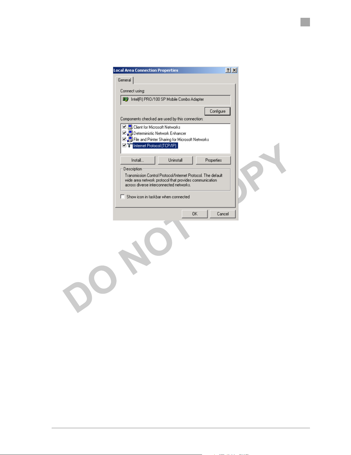
2. Right-click on the Local Area Connection icon that belongs to the Ethernet
controller connected to the AP, and select Properties.
2-2 • AP User’s Guide Atheros Communications, Inc.
2-2 • March 2003 COMPANY CONFIDENTIAL
Chapter
2
3. Within the Local Area Connection Properties dialog box, choose Internet
Protocol (TCP/IP) and click Properties.
Atheros Communications, Inc. AP Network Attachment and Configuration • 2-3
COMPANY CONFIDENTIAL March 2003 • 2-3

2
Chapter
4. Configure the IP address for the Ethernet connection in the Internet
Protocol (TCP/IP) Properties dialog box.
5. Click OK to continue and close the Internet Protocol Properties dialog
box.
2-4 • AP User’s Guide Atheros Communications, Inc.
2-4 • March 2003 COMPANY CONFIDENTIAL

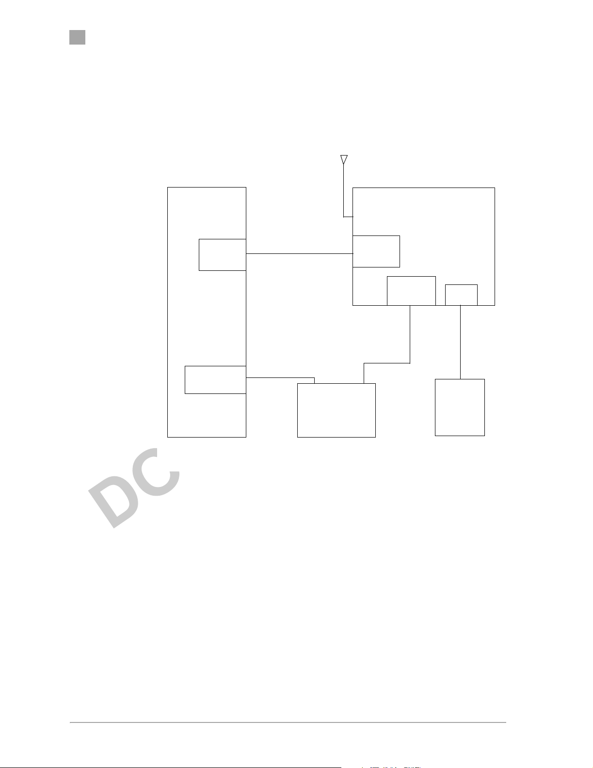
AP Hardware Configuration
The Atheros AP hardware allows the configuration of one WLAN. Figure 2-2
shows the physical location of WLAN, panel connectors on the AP hardware,
and the location of the antenna cable and external dipole antenna. An
additional integrated antenna may be provided. Tab le 2 -1 summarizes the
type of cable to use when using the Ethernet wired ports on the AP. You may
use either, or both Ethernet ports.
2.4 GHz
Antenna
(black)
WLAN
Chapter
2
Power
Ethernet 0
Ethernet 1
Serial Connection
Figure 2-2. AP Physical Description
Table 2-1. Ethernet Port Configuration
Ethernet Port Number Dumb Hub or Switch Computer Auto-Sensing Hub or Switch
0 Crossover cable Straight cable Crossover or straight cable
1 Straight cable Crossover cable Crossover or straight cable
Atheros Communications, Inc. AP Network Attachment and Configuration • 2-5
COMPANY CONFIDENTIAL March 2003 • 2-5

2
Chapter
AP Initial Configuration
This section describes how to configure the AP after booting from Flash
memory. Refer to “Firmware Update Configuration Window” on page A-21
to load the Operating image file to the Flash file system, if the operating
system software should be updated.
Configure the AP for its channel frequency and Service Set Identifier (SSID)
unique to the application. This configuration can be done either through a
web browser with access to the built-in AP web server, or by issuing
commands through the command line interface (CLI).
The AP can be configured at any time to tailor it for the application
environment. For more information on configuring the AP using the web
browser, refer to “AP Web Server” in Appendix A. For more information on
using the CLI, refer to “AP Command-Line Interface” in Appendix B.
The following description illustrates the use of the web browser. For
information on using the CLI, refer to “Command-Line Interface” on
page 2-9.
Web Browser
Follow these steps to configure the channel frequency and SSID using a web
browser:
1. Launch a web browser (Netscape Navigator or Internet Explorer are
examples of commonly used web browsers).
2. From the HPC, enter the IP address that is assigned to the AP as the URL
address, for example http://192.168.1.1.
2-6 • AP User’s Guide Atheros Communications, Inc.
2-6 • March 2003 COMPANY CONFIDENTIAL

Chapter
The Access Point Web Server homepage will appear (see Figure 2-3).
2
Figure 2-3. AP Web Server Homepage
3. Select the Access Point Web Server hotlink.
4. A dialog box appears requesting login authorization. When prompted,
enter the following information to log in:
Log in: Admin (case-sensitive)
Password: 5up
5. Click OK to complete the login process.
6. Select the Configuration hotlink from the navigation menu.
Atheros Communications, Inc. AP Network Attachment and Configuration • 2-7
COMPANY CONFIDENTIAL March 2003 • 2-7

2
Chapter
The System Configuration window appears (see Figure 2-4).
Figure 2-4. System Configuration Window
7. Enter the SSID (name or address) for the AP in the SSID field. The SSID
must be 1–32 characters in length.
To configure a single SSID to have more than one AP in a single SSID,
specify a unique System Name for each AP within that single SSID.
Depending on firmware settings, the channel of operation may not be
accessible and will be automatically determined depending on the current
regulatory domain (i.e. country of operation).
2-8 • AP User’s Guide Atheros Communications, Inc.
2-8 • March 2003 COMPANY CONFIDENTIAL

8. Click Update to commit the changes.
Change other settings at this time. Refer to Appendix A for more
information about each configuration option.
9. After all configuration changes are complete, reboot the AP to enable
them. To reboot the AP, click on the REBOOT AP button that appears.
Command-Line Interface
The following procedures show the steps required to configure the AP SSID
and channel frequency (where allowed) using the command-line (CLI)
interface and Telnet.
Chapter
2
After the AP boots and the operating system software loads, use Telnet to
access the AP through the default AP IP address as follows:
1. Select Start > Run from the Microsoft Win2K tool bar.
2. Type cmd in the Open dialog box and click OK.
3. In the command line prompt, type telnet 192.168.1.20 and press the Enter
key.
4. When prompted, enter the following information to log in:
Username: Admin (case sensitive)
Password: 5up
5. Press Enter to complete the login process. The Atheros Access Point
Software revision prompt appears:
Atheros Access Point Rev. X.Y.Z
6. Use the set ssid <SSID> command to specify the SSID.
7. Use the set channel <channel> command to change the radio channel.
8. Use the reboot command and then press Enter, which reboots the AP, to
enable any changes.
9. To view CLI command options, use the help command or refer to
Appendix B for details about CLI options.
Atheros Communications, Inc. AP Network Attachment and Configuration • 2-9
COMPANY CONFIDENTIAL March 2003 • 2-9

2
Chapter
2-10 • AP User’s Guide Atheros Communications, Inc.
2-10 • March 2003 COMPANY CONFIDENTIAL

A
A
AP Web Server
Configure the access point (AP) either through a web browser interface to the
AP web server, or using the command-line interface (CLI) through telnet. The
web server resides in the AP and is accessible from any station (STA) that is
connected to the AP Infrastructure network.
This appendix describes configuring the AP through the AP Web Server.
Accessing the AP Web Server
Follow these steps to access the AP Web Server:
1. Launch a web browser (Netscape Navigator or Internet Explorer are
examples of commonly used web browsers).
2. From the HPC, enter the IP address that is assigned to the AP as the URL
address. For example, enter http://192.168.1.1.
Atheros Communications, Inc. AP Web Server • A-1
COMPANY CONFIDENTIAL March 2003 • A-1

A
Appendix
The Access Point Web Server homepage appears (see Figure A-1).
Figure A-1. AP Web Server Homepage
Customize the appearance of the Access Point Web Server homepage by
replacing any of the three .GIF files used on the page. Use FTP to store the
replacement .GIF files to the AP. Ta bl e A- 1 summarizes the three .GIF
files to replace to customize the homepage.
Table A-1. Homepage .GIF Files
Filename Description
logo.gif Replaces the current Atheros logo with another .GIF
file.
tagline.gif Replaces the tagline “Driving the wireless future” with
a new tagline.
cover.jpe Replaces the Atheros AR5001AP chipset photograph
with a new photograph.
For example, the .GIF file containing the full path filename for a company
logo can be replaced with another .GIF file.
3. Select the Atheros Access Point Web Server hotlink.
A-2 • AP User’s Guide Atheros Communications, Inc.
A-2 • March 2003 COMPANY CONFIDENTIAL

Appendix
4. A dialog box appears requesting login authorization. When prompted,
enter the following information to log in:
Log in: Admin (case sensitive)
Password: 5up
A
5. Click OK to complete the login process.
NOTE: The web browser must support frames and Java script must be enabled.
Atheros Communications, Inc. AP Web Server • A-3
COMPANY CONFIDENTIAL March 2003 • A-3

A
Appendix
The Access Point Web Server Statistics window appears (see Figure A-2.)
Figure A-2. Statistics Window
A-4 • AP User’s Guide Atheros Communications, Inc.
A-4 • March 2003 COMPANY CONFIDENTIAL

Configuration Windows
The Web Server Configuration windows allow viewing and editing of
configuration information for the AP. The Web Server provides configuration
windows for:
■ System configuration parameters
■ 2.4 GHz radio configuration parameters
■ 2.4 GHz statistics
■ Security
■ Configuration scripts
■ Firmware updates
To access any of these AP configuration screens, click on the desired hotlink
from the navigation bar on any configuration screen (see Figure A-3.)
Appendix
A
Figure A-3. AP Web Server Navigation Bar
Atheros Communications, Inc. AP Web Server • A-5
COMPANY CONFIDENTIAL March 2003 • A-5

A
Appendix
Working with Configuration Windows
The Web Server Configuration windows provide a user-friendly interface to
aid in quick configuration of the AP. After making any additions or changes
to any configuration window, update the configuration file to save the
changes. The new configuration is not in effect until the AP is rebooted.
Follow these steps to update configuration files:
1. Enter the configuration updates or changes in the appropriate
configuration fields.
2. Click Update.
3. Click Reboot AP to make the changes effective.
The web server loses connectivity with the Web Server as the AP reboots.
To reestablish the connection with the Web Server, wait until the AP has
completed rebooting and navigate to the Web Server to resume
communication.
A-6 • AP User’s Guide Atheros Communications, Inc.
A-6 • March 2003 COMPANY CONFIDENTIAL

System Configuration Window
The System Configuration window allows the setting of general operating
information for the AP. Click on Configuration from any window to access
the System Configuration window (see Figure A-4).
Appendix
A
Figure A-4. AP System Configuration Window
Other settings can also be changed at this time.
Atheros Communications, Inc. AP Web Server • A-7
COMPANY CONFIDENTIAL March 2003 • A-7

A
Appendix
Ta bl e A- 2 summarizes the data fields on the System Configuration window.
Table A-2. System Configuration Window Field Descriptions
General Configuration Field Description
User Name Specifies the user name.
Password Specifies the password.
System Name Specifies a unique name for AP. Enter a unique text
string of up to 32 characters in length.
Enable Telnet Use the checkbox to allow telneting into the AP.
Country Specifies the country where the AP is operating. Use
the drop-down menu to specify the country where
the equipment will operate from. The allowable
choices may be limited by firmware installed on
your version of the product depending on
Regulatory Domain (country) of operation.
IP Address Specifies the IP address of the AP.
Subnet Mask Specifies the subnet mask for the AP.
Default Gateway Address Specifies the default gateway for the AP.
2.4 GHz Radio Use the radio buttons to enable/disable 2.4 GHz
radio operation.
Edit 2.4 GHz Radio Settings Click this button to edit the configuration for 2.4
GHz radio operation. (refer to“2.4 GHz Radio
Configuration Window” on page A-9).
A-8 • AP User’s Guide Atheros Communications, Inc.
A-8 • March 2003 COMPANY CONFIDENTIAL

2.4 GHz Radio Configuration Window
The 2.4 GHz Radio Configuration window allows the setting of generic 2.4
GHz radio operating information for the AP. The Device’s firmware may
limit the allowable settings depending on Regulatory Domain (country) of
operation. From the AP System Configuration window, click on Edit 2.4 GHz
Radio Settings to access the 2.4 GHz Radio Configuration window (see
Figure A-5).
Appendix
A
Figure A-5. 2.4 GHz Radio Configuration Window
Atheros Communications, Inc. AP Web Server • A-9
COMPANY CONFIDENTIAL March 2003 • A-9

A
Appendix
Ta bl e A- 3 summarizes the data fields on the 2.4 GHz Radio Configuration
window.
Table A-3. 2.4 GHz Radio Configuration Window Field Descriptions
General Configuration Field Description
SSID Identification of the AP. Enter a number or address
between 1 and 32 characters in length that the STAs
are associating with in Infrastructure mode. More
than one AP in an SSID can be specified here. Use
the System Name field to uniquely identify each AP.
Suppress SSID Use the checkbox to prevent broadcast of the AP’s
SSID in beacons. When enabled, the SSID in beacons
are not transmitted and only those STAs with prior
knowledge of an AP’s SSID can associate with that
AP.
Wireless Mode The wireless LAN mode specifies both frequency
range and data rates. Firmware loaded on your
version of the Access Point may limit channel setting
depending on the Regulatory Domain (country) of
operation
Security: Edit Security Settings Click here to edit the security configuration for 2.4
GHz radio operation
Advanced Settings Click here to enter advanced configuration for 2.4
GHz radio operation (refer to “2.4 GHz Radio
Advanced Configuration Window” on page A-18).
A-10 • AP User’s Guide Atheros Communications, Inc.
A-10 • March 2003 COMPANY CONFIDENTIAL

2.4 GHz Security Configuration Window
The 2.4 GHz Radio Security Configuration window allows the setting of
security information for the AP. From the 2.4 GHz Radio Configuration
window, click on Edit Security Settings to access the 2.4 GHz Security
Configuration window (see Figure A-6).
Appendix
A
Figure A-6. 2.4 GHZ Security Configuration Window
Atheros Communications, Inc. AP Web Server • A-11
COMPANY CONFIDENTIAL March 2003 • A-11

A
Appendix
Ta bl e A- 4 summarizes the data fields on the 2.4 GHz Security Configuration
window.
Table A-4. 2.4 GHz Security Field Descriptions
Security Configuration Field Description
Security Mode Use the radio buttons to specify the security mode.
Security Server Click Edit Security Server Settings to change the
configuration of the security server.
Key Entry Method Use the radio buttons to specify the key entry method
as either hexadecimal or ASCII.
Default Shared Key Use the radio button to specify which encryption key to
use as the default shared key.
Encryption Key Specifies the encryption key used for broadcast/
multicast frames.
Key Length Specifies the key length:
■ None
■ 10 Hex digits or 5 ASCII text
■ 26 Hex digits or 13 ASCII text
■ 32 Hex digits or 16 ASCII text
Access Control List Specifies the state of the Access Control List (ACL). Use
the drop-down menu to specify the state of ACL,
where:
■ Disable—Unrestricted Access: By default, while
checking of the ACL is enabled, the access control
list itself is empty. This is the same as disabling the
checking on the ACL.
■ Enable—Restricted Access: An ACL entry must
exist before ACL can be enabled. While ACL is
enabled, stations with valid shared keys and
stations with matching “allow” entries on the ACL
are authenticated.
■ Strict—Restricted (w/ACL match): Requires an
ACL entry that specifies the station's assigned
unique key or the station is denied association. In
the strict mode, stations with valid share keys and
not on the ACL are not authenticated. The stations
must have unique keys defined and matching
“allow” ACL entries specified, in order to associate
with the AP.
Edit ACL Settings Click here to edit the configuration of the ACL
operation for 2.4 GHz (refer to “2.4 GHz Access Control
List Configuration Window” on page A-15).
A-12 • AP User’s Guide Atheros Communications, Inc.
A-12 • March 2003 COMPANY CONFIDENTIAL

Edit Security Server Settings
The RADIUS Server Configuration window allows configuration of a
RADIUS server for authentication purposes in 802.1X networks. See
Figure A-7 for an illustration of the RADIUS Server Configuration window.
Appendix
A
Figure A-7. 2.4 GHz RADIUS Server Configuration Window
Ta bl e A- 5 summarizes the data fields on the 2.4 GHz RADIUS Server
Configuration window.
Table A-5. 2.4 GHz RADIUS Server Configuration Field Descriptions
Security Configuration Field Description
Domain Name Server IP
Address
Domain Name Server Specifies the name of the domain name server.
RADIUS Server Specifies the IP address of the RADIUS server.
RADIUS Port Specifies the port of the RADIUS server.
Specifies the IP address of the domain name server.
Atheros Communications, Inc. AP Web Server • A-13
COMPANY CONFIDENTIAL March 2003 • A-13

A
Appendix
Table A-5. 2.4 GHz RADIUS Server Configuration Field Descriptions
Security Configuration Field Description
RADIUS Secret Specifies the password for the RADIUS server.
RADIUS Key Source Specifies the location of the RADIUS keys.
2.4 GHz 802.1X Configuration
The IEEE 802.1X protocol is designed to support port-based authentication
and secure key distribution. It can be used to distribute unique encryption
keys for an entire BSS. Atheros provides support for this protocol on both the
AP and the STA.
To enable 802.1X on the AP, take the following steps on the 2.4 GHz RADIUS
Server Configuration window:
Use the “local” checkbox to specify the RADIUS keys
are located in the AP.
Use the “remote” checkbox to specify the RADIUS keys
are located in the RADIUS server.
1. Specify the domain name server IP address.
2. Specify the name of the domain server.
3. Specify a RADIUS Server name.
4. Specify a RADIUS Server secret.
5. Specify the location of the 2.4 GHz Key Source as Remote.
A-14 • AP User’s Guide Atheros Communications, Inc.
A-14 • March 2003 COMPANY CONFIDENTIAL

2.4 GHz Access Control List Configuration Window
The 2.4 GHz Radio Configuration window allows the setting of security
information for the AP. From the 2.4 GHz Security Configuration window,
click on Edit ACL Settings to access the 2.4 GHz ACL Configuration window
(see Figure A-8).
Appendix
A
Figure A-8. 2.4 GHz Access Control List Configuration Window
Click Delete to remove any list item.
Atheros Communications, Inc. AP Web Server • A-15
COMPANY CONFIDENTIAL March 2003 • A-15

A
Appendix
Adding New Access Control Lists
The 2.4 GHz Security New ACL Configuration window allows you to add
new access control list item. From the 2.4 GHz ACL Configuration window,
click Add to list to enter new list items (see Figure A-9).
Figure A-9. 2.4 GHz New Access Control List Configuration Window
Ta bl e A- 6 summaries the data fields on the 2.4 GHz New Access Control List
window
Table A-6. 2.4 GHz New Access Control List Field Descriptions
Per Station Privacy Field Description
MAC Address Specifies the MAC address for the STA to be included
in the ACL.
ACL Type Specifies the current state of each STA, where:
■ Allowed—Enable access for this MAC address to
the ACL.
■ Denied—Deny access for this MAC address to the
ACL.
■ Default Shared Key—This MAC address would use
the default shared key.
■ 64/128/152 Bits—Specifies lengths for shared keys.
Unique Key Enter a unique key.
A-16 • AP User’s Guide Atheros Communications, Inc.
A-16 • March 2003 COMPANY CONFIDENTIAL

Adding Access Control List Permissions
The 2.4 GHz ACL Configuration window allows you to add permission for
each list item. From the 2.4 GHz ACL Configuration window, click on a MAC
address in the list to view the 2.4 GHz Security Edit ACL Configuration
window (see Figure A-10).
Appendix
A
Figure A-10. 2.4 GHz Security Edit ACL Configuration Window
Ta bl e A- 7 summaries the data fields on the 2.4 GHz Security Edit ACL
Configuration window.
Table A-7. 2.4 GHz Security Edit Access Control List Field Descriptions
Per Station Privacy Field Description
Permission Specifies the current state of each STA, where:
■ Allowed—Enable access for this MAC address to
the ACL.
■ Denied—Deny access for this MAC address to the
ACL.
■ Default Shared Key—This MAC address would use
the default shared key.
■ 64/128/152 Bits—Specifies lengths for shared keys
Unique Key Enter a unique key.
Atheros Communications, Inc. AP Web Server • A-17
COMPANY CONFIDENTIAL March 2003 • A-17

A
Appendix
2.4 GHz Radio Advanced Configuration Window
The 2.4 GHz Radio Advanced Configuration window allows the setting of 2.4
GHz advanced, radio operating information for the AP. Device’s firmware
may limit allowable settings depending on Regulatory Domain (country) of
operation. From the 2.4 GHz Radio Configuration window, click on
Advanced to access the 2.4 GHz Radio Advanced Configuration window (see
Figure A-11).
Figure A-11. 2.4 GHz Radio Advanced Configuration Window
A-18 • AP User’s Guide Atheros Communications, Inc.
A-18 • March 2003 COMPANY CONFIDENTIAL

Appendix
A
Ta bl e A- 8 summarizes the data fields on the 2.4 GHz Radio Advanced
Configuration window.
Table A-8. 2.4 GHz Radio Advanced Configuration Window Field Descriptions
Advanced Configuration Field Description
Data Rate Specifies rate of data transmission. Select the
desired rate from the drop-down menu. The
Best selection will adapt the rate to the best
available.
Beacon Interval Specifies the Beacon Interval value. Enter a
value between 20 and 1000.
Data Beacon Rate Specifies the Data Beacon Rate. Enter a value
between 1 and 16384 that specifies the Delivery
Traffic Indication Message (DTIM).
Fragment Length Specifies the fragment length. Enter a value
between 256 and 2346.
RTS/CTS Threshold Specifies the value of the RTS/CTS threshold.
Enter a value between 256 and 2346.
Short Preamble Use the radio button to specify short preamble
(11b) usage. When enabled, both short and long
preambles are used. When disabled, only long
preambles are used.
Allow 2.4 GHz 54 Mbps Stations
Only
Protection Mode Specifies the operation of CTS protection mode:
Protection Rate Specifies the operation of CTS protection rate:
Protection Type Specifies the operation of CTS protection type:
Short Slot Time Use the radio button to specify short time shot
Use the radio button to enable or disable the
association of 2.4 GHz 54 Mbps station only.
■ None
■ Always
■ Auto
■ 1 Mbps
■ 2 Mbps
■ 5.5 Mbps
■ 11 Mbps
■ CTS only
■ RTS-CTS
usage.
Atheros Communications, Inc. AP Web Server • A-19
COMPANY CONFIDENTIAL March 2003 • A-19

A
Appendix
Script Configuration Window
The Script Configuration window allows execution of text scripts of CLI
commands. For example, construction of a text script to enter the shared keys
for stations. All set commands can be used in scripts, except set security, set
password, find bss, ftp, password, and ping.
Figure A-12 illustrates an example of an AP Script Configuration Window.
Figure A-12. Configuration Script Configuration Window
Follow these steps to use scripts:
1. Develop the scripts for the application.
2. Enter the host name where the script resides.
3. Enter the user name and password for the host.
4. Specify the script path and the script name in the data entry fields in the
Configuration Script window.
5. Click Execute to run the script.
To revert to the previous configuration, click Restore.
A-20 • AP User’s Guide Atheros Communications, Inc.
A-20 • March 2003 COMPANY CONFIDENTIAL

Firmware Update Configuration Window
The Firmware Update Basic Configuration window allows viewing of the
FTP location of new firmware. The default values for the Host Name, Image
Path, and Image Name appear in the window.
To access the Firmware Update window, click on Firmware Update in the
navigation bar. The Firmware Update Configuration Window appears
(see Figure A-13).
Appendix
A
Figure A-13. AP Firmware Update Configuration Window
The AP uses the File Transfer Protocol (FTP) to download the Operating
image from the HPC. An FTP server utility is required to perform the data
transfer between the AP and HPC.
Atheros Communications, Inc. AP Web Server • A-21
COMPANY CONFIDENTIAL March 2003 • A-21

A
Appendix
Follow these steps to enable firmware updates:
1. From the Firmware Update Basic window, click on Advanced.
The AP Firmware Update Advanced Configuration window appears
(see Figure A-14).
Figure A-14. Advanced Firmware Update Configuration Window
The Firmware Update Advanced Configuration window allows the
setting of new information on the FTP location of new firmware or
filename of the firmware.
2. Enter the Host Name or host PC’s IP address, User Name, Password,
Image Path, and Image Name in the data-entry fields.
To revert to the default-vendor values, click Use Factory FTP Location.
3. Click Update Firmware to store the new firmware changes.
To restore the previous firmware, click Restore.
A-22 • AP User’s Guide Atheros Communications, Inc.
A-22 • March 2003 COMPANY CONFIDENTIAL

Statistics Windows
From the AP Web Server, choose the Statistics hyperlink to go to the Access
Point Statistics window. By default, this is the first window that appears once
the AP Web Server opens.
The AP Statistics window allows viewing of the assigned ID, MAC address,
and current state of the AP and all stations currently part of its BBS (Basic
Service Set). The top-level Statistics window automatically updates each
minute.
AP Statistics
To view statistics on the AP, click on the MAC address hyperlink for the
desired AP in the Statistics window. The BSS Stats window for the selected
AP will appear. See Figure A-15 for an example of a BSS Stats window for an
AP.
Appendix
A
Figure A-15. Basic Service Set Statistics Window for an AP
Atheros Communications, Inc. AP Web Server • A-23
COMPANY CONFIDENTIAL March 2003 • A-23

A
Appendix
The BSS Stats window for AP is divided into sections that provide the AP
configuration, Access Point SME statistics (station association information), or
Access Point (Transmit and Receive) Statistics. Refer to Tab le A- 9 for a
description of the BSS Statistics for AP window fields.
Table A-9. BSS Stats Field for AP Descriptions
BSS Stats Field Description
State Current state of the AP.
Authentication Type Specifies open-system or shared key.
Encryption Specifies the enabled state of encryption; either yes
or no.
Cipher Advertised Specifies current state of advertised cipher
negotiations, AES and/or WEP, and None (clear).
Authentication/Deauthentication Number of times a STA attempted authentication
and deauthentication.
Association/Deassociation Number of times a STA attempted associations and
deassociations.
MSDU Maximum Service Data Unit. Specifies the number
of packets sent and received by the AP.
Data/Management/Control Packets can either be data, control, or management.
Specifies the number of packets sent and received
for each.
Multicast Specifies the number of multicast packets both sent
and received.
Errors Specifies the error count for both transmit and
receive.
Receive Errors Specifies the number of receive errors.
Discarded Frames Specifies the number of receive discarded frames.
Duplicate Frames Specifies the number of receive duplicate frames.
CRC Errors Specifies the number of receive CRC errors.
PHY Errors Specifies the number of receive PHY errors.
DMA Errors Specifies the number of receive DMA errors.
Transmit Errors Specifies the number of transmit errors.
Discarded Frames Specifies the number of transmit discarded frames.
Excessive Retries Specifies the number of transmit excessive retries.
DMA Errors Specifies the number of transmit DMA errors.
The AP Stats window automatically updates every five seconds.
A-24 • AP User’s Guide Atheros Communications, Inc.
A-24 • March 2003 COMPANY CONFIDENTIAL

Station Statistics
To view statistics on any STA, click on the MAC address hyperlink for the
desired STA. The BSS Stats window for the selected STA will appear. See
Figure A-16 for an example BSS Stats window for a station.
Appendix
A
Figure A-16. Basic Service Set Statistics Window for Station
The BSS Stats window for stations provides the station configuration and
statistics for the selected station.
Atheros Communications, Inc. AP Web Server • A-25
COMPANY CONFIDENTIAL March 2003 • A-25

A
Appendix
Ta bl e A- 10 summarizes the information fields on the BSS Stats window for
aSTA.
Table A-10. BSS Stats Fields for STA Descriptions
BSS Stats Window for STA Field Description
AID The ID of the STA.
State The current state of the STA
Power Save Specifies the enabled state of the power save option;
either yes or no.
Encryption Specifies current state of encryption; AES and/or
WEP, and None (clear).
Advertised Cipher Specifies the supported cipher types.
Unicast Cipher Specifies the current unicast cipher type used.
Multicast Cipher Specifies the current multicast cipher type used.
Authentication/Deauthentication Number of times a STA attempted authentication and
deauthentication.
Association/Deassociation Number of times a STA attempted associations and
deassociations.
MSDU Maximum Service Data Unit. Specifies the number of
packets sent and received by the STA.
Data/Management/Control Packets can either be data, control, or management.
Specifies the number of packets sent and received for
each.
Multicast Specifies the number of multicast frames.
Errors Specifies the error count for both transmit and receive
sides.
Signal Strength Specifies the strength of the transmit and receive
signals in dBm.
Data Rate (Mbps) Specifies the transmit and receive data rate in Mbps.
Receive Errors Specifies the number of receive errors.
Discarded Frames Specifies the number of receive discarded frames.
Duplicate Frames Specifies the number of receive duplicate frames.
CRC Errors Specifies the number of receive CRC errors.
PHY Errors Specifies the number of receive PHY errors.
DMA Errors Specifies the number of receive DMA errors.
Transmit Errors Specifies the number of transmit errors.
Discarded Frames Specifies the number of transmit discarded frames.
Excessive Retries Specifies the number of transmit excessive retries.
DMA Errors Specifies the number of transmit DMA errors.
A-26 • AP User’s Guide Atheros Communications, Inc.
A-26 • March 2003 COMPANY CONFIDENTIAL

B
B
Regulatory Compliance
Information
This section includes user requirements for operating this product in
accordance with National laws for usage of radio spectrum and operation of
radio devices. Failure of the end-user to comply with the applicable
requirements may result in unlawful operation and adverse action against the
end-user by the applicable National regulatory authority.
NOTE: The Atheros Access Point firmware limits operation to only the channels
allowed in a particular Region or Country (i.e. Regulatory Domain). Therefore, all
options described in this user’s guide may not be available in your version of the
device.
Atheros Communications, Inc. Regulatory Compliance Information • B-1 COMPANY CONFIDENTIAL February 2003 • B-1

B
Appendix
FCC Requirements for Operation in the Unites States
Radio Frequency Interference Warnings & Instructions
This equipment has been tested and found to comply with the limits for a
Class B digital device, pursuant to Part 15 of the FCC Rules. These limits are
designed to provide reasonable protection against harmful interference in a
residential installation. This equipment uses and can radiate radio frequency
energy and, if not installed and used in accordance with the instructions, may
cause harmful interference to radio communications.
However, there is no guarantee that interference will not occur in a particular
installation. If this equipment does cause harmful interference to radio or
television reception, which can be determined by turning the equipment off
and on, the user is encouraged to try to correct the interference by one or
more of the following methods:
• Reorient or relocate the receiving antenna
• Increase the separation between the equipment and the receiver
• Connect the equipment into an electrical outlet on a circuit
different from that which the radio receiver is connected
• Consult the dealer or an experienced radio/TV technician for
help.
Modifications made to the product, unless expressly approved by Atheros
Communication, could void the user ’s right to operate the equipment.
B-2 • AP User’s Guide Atheros Communications, Inc.
B-2 • February 2003 COMPANY CONFIDENTIAL

RF Exposure
CAUTION: To ensure compliance with FCC RF exposure requirements, the antenna
used for this device must be installed to provide a separation distance of at least 20
cm from all persons and must not be located or operated in conjunction with any
other antenna or radio transmitter.
Declaration Of Conformity
We Atheros Communications, Inc.,
529 Almanor Ave.,Sunnyvale,CA 94085
declare under our sole responsibility that this product complies with Part 15
of FCC Rules. Operation is subject to the following two conditions:
Appendix
B
• This device may not cause harmful interference, and
• This device must accept any interference received, including
interference that may cause undesired operation.
Atheros Communications, Inc. Regulatory Compliance Information • B-3
COMPANY CONFIDENTIAL February 2003 • B-3

B
Appendix
B-4 • AP User’s Guide Atheros Communications, Inc.
B-4 • February 2003 COMPANY CONFIDENTIAL
 Loading...