

Page 1
User Manual for
Flying Probe Test System
V3.7
Page 2

A-2
Test system A 3 V3.7
The test system may only be started, operated and turned off by a trained operator. A
trained supervisor may only carry out the password-protected operations.
Before turning on the system, the operator must have read this quick reference manual
especially observing the documented safety precautions.
As far as no appropriate training on part of the company atg has taken place the
operator is not authorized to carry out the following activities:
- Transport
- Assembly
- Mounting
- Putting into operation
- Adjustment
- Repair
- Trouble shooting
- Putting out of operation
- Disassembly
The Reader should be familiar with the use of Windows.
This transcript only represents a draft. Therefore, it may not be accepted as faultless
and complete. We reserve the right for technical changes and errors.
This handbook is protected by copyright. All rights reserved. Duplications of any kind,
storage and translations only by written permission of
atg test systems GmbH
Zum Schlag 3
D-97877 Wertheim
Germany
Tel. 00 49 (0) 93 42 / 2 91 - 0
Fax 00 49 (0) 93 42 / 3 95 10
E-mail: [email protected]
Internet: www.atg-test-systems.de
This manual can be corrected and adapted to the technical progress at any time
without prior notice. 6/2001
Page 3

A-3
Test System A 3 V3.7
Table of Contents
Directions for avoiding personal injuries .............................................................A-6
atg test systems Software Certificate...................................................................A-9
Information for users............................................................................................A-9
1. System Overview..........................................................................................A-10
1.1 Unloading and Transporting the Flying Probe Test System A3...................A-10
1.2 General View of the Test System................................................................A-12
1.3 General View of the Shuttle ........................................................................A-14
1.4 Assembly Rack...........................................................................................A-16
1.5 Test Requirement for Repaired Boards ......................................................A-18
1.6 The Operating Modes of the A3 Test System .............................................A-19
2. Turning on the Test System...........................................................................A-20
3. The User Mode...............................................................................................B-1
3.1 The User Interface of the User Mode .............................................................B-1
3.1.1 Status Field ................................................................................................B-2
3.1.2 Buttons .......................................................................................................B-3
3.2 Load job ........................................................................................................ B-4
4. Adjusting to a New Board................................................................................B-6
4.1 Ejecting the Shuttle .......................................................................................B-6
4.2 Adjusting the Product Holders.......................................................................B-7
4.2.1 Selecting the proper Terminal Bar Sizes ....................................................B-7
5. Starting a Test in User Mode .........................................................................B-10
5.1 Button Test Params (F5) in the User Mode..................................................B-12
5.1.1 Tab-box: Skip panels................................................................................B-12
5.1.2 Tab-Box: Misc...........................................................................................B-13
5.2 Scanning (Determining the board position with the camera) .......................B-15
5.2.1 Manual scanning ......................................................................................B-17
5.2.2 Automatic scanning ..................................................................................B-18
5.2.3 Wrong Board Position...............................................................................B-19
5.2.4 Canceling the scanning process ..............................................................B-19
Page 4

A-4
Test system A 3 V3.7
5.2.5 The Beginning of the Test ........................................................................B-20
5.2.6 Pausing and Resuming a Test .................................................................B-20
5.2.7 Canceling the test....................................................................................B-20
5.3 Test Result Output......................................................................................B-21
6. Removing the tested Board and inserting a new One...................................B-24
6.1 Turning off the Test System.........................................................................B-24
7. The Supervisor Mode ......................................................................................C-1
7.1 Introduction....................................................................................................C-1
7.2 Switching to the Supervisor Mode .................................................................C-2
7.3 Changing the Password ................................................................................C-4
7.4 Generate Service Data ..................................................................................C-5
7.5 Test statistics.................................................................................................C-6
7.6 The operating window of the supervisor mode ..............................................C-7
7.7 The Functions of the new Supervisor Mode Buttons ....................................C-8
7.8 The Main Menus of the Supervisor Mode .....................................................C-9
7.8.1 The Main Menu Faults................................................................................C-9
7.8.2 The Menu Items of the Main Menu Faults.................................................C-10
7.8.3 Main Menu Debug ....................................................................................C-17
7.8.4 Main Menu Options...................................................................................C-23
7.8.5 Main Menu Item Show <boardname> .......................................................C-24
7.8.6 The Main Menu Tools...............................................................................C-33
7.8.7 Main Menu View.......................................................................................C-37
7.8.8 Main Menu Scanmarks .............................................................................C-37
7.8.9 Main Menu Antennae ...............................................................................C-41
7.8.10 Main Menu Faults ...................................................................................C-43
7.8.11 Main menu Markers ................................................................................C-46
7.8.11 The Main Menu Item Close.....................................................................C-46
7.9 Action Buttons of the Supervisor Mode........................................................C-47
7.9.1 Button Test Params (F5)...........................................................................C-49
8. Appendix ........................................................................................................D-1
8.1 Starting the Debugger ...................................................................................D-1
8.2 How to Calibrate the A 3 Test System ...........................................................D-2
8.3.1 Executing the C-Adjust ..............................................................................D-6
8.4 Exchanging a Test Needle ............................................................................D-8
8.4.1 Checklist for the Test Needle Exchange.....................................................D-8
8.4.2 Exchanging the Test Tip.............................................................................D-9
Page 5

A-5
Test System A 3 V3.7
8.4.3 Removal of the entire Needle Fixture .........................................................D-9
8.5 Z-Axis Removal...........................................................................................D-11
8.6 Z-Axis Installation........................................................................................D-13
8.6.1 Preparation...............................................................................................D-13
8.6.2 Assembly..................................................................................................D-14
8.6.3 Final Test..................................................................................................D-15
8.6.4 Error Messages after Z-axis Installation and their Probable Causes ........D-16
8.7 Avoiding Test Head Damages ....................................................................D-18
8.8 Testing Flexible PCBs .................................................................................D-19
8.8.1 The Simple frame .....................................................................................D-19
8.8.2 The Sandwich frame.................................................................................D-20
8.9 The Application of a Test tray for Testing Flexible Boards ..........................D-21
8.10 The A 3-Test Protocol................................................................................D-23
8.11 Brief Flow Chart of Data Preparation.........................................................D-26
8.12 Technical Specifications A 3 .....................................................................D-27
8.13 Maintenance Plan .....................................................................................D-29
Page 6

A-6
Test system A 3 V3.7
Directions for avoiding personal injuries
In order to avoid personal injuries, the following directions should be paid attention to:
General Directions
Observe all safety and danger directions on the test system.
Only electrical specialists or trained personnel supervised and guided by an electrical
specialist according to the electrical engineering regulations are authorized to carry
out work on the electrical equipment of the test system.
Take measures to only operate the machine in safe and functional condition!
Only operate the machine if all safety precautions and safety required equipment e.g.
detachable safety equipment, emergency off furnishings, etc. are installed and
functional!
In case of operational malfunctions immediately turn off and secure the machine!
Malfunctions must be eliminated promptly!
Electrical Energy
Use only original fuses with the proper current intensity! Turn off the machine
immediately in case of defects in the electrical power supply!
Only electrical specialists or trained personnel supervised and guided by an electrical
specialist according to the electrical engineering regulations are authorized to carry
out work on the electrical equipment of the test system.
Machine and system parts needing inspection, repair or maintenance must be voltage
free - if required. First, check the powerless parts for residual voltage then ground and
short-circuit them and isolate neighboring powered parts!
The electrical equipment is to be inspected/tested regularly. Defects as for example
loose connections or burnt cables must be eliminated immediately.
If it is necessary to carry out work on powered parts call in a second person that in case
of an emergency can push the emergency-off button which turns off the voltage.
Secure the work area with a red-white security chain and an appropriate warning sign!
Use only insulated tools!
Page 7

A-7
Test System A 3 V3.7
In case of working on high voltage assembly racks connect the power cable to the
ground after switching the power off. Then short-circuit the assembly components
such as the capacitors with a grounding bus.
Safety Directions for Product Defects
In order to avoid product defects the following should be observed:
Do not carry out any program changes (software) to programmable control systems!
Organizational Directions
General Directions
This manual should be kept in reach of the test system at all times!
In addition to the operator’s manual, universally valid and other obligatory regulations
concerning the prevention of accidents and environmental protection should be
observed and instructed!
Safety and danger consciousness among the personnel should be controlled regularly,
in consideration of the operator’s manual!
All safety and danger directions affixed to, at and on the test system must be visible and
clearly readable!
Without prior permission of the manufacturer, do not carry out any exchange, add-on
or reconstruction activities that could impair the machine’s safety!
Spare parts must meet the manufacturer set technical requirements. This is always
guaranteed with original spare parts!
Make sure to meet the deadlines stated in the operator’s manual for recurrent tests/
inspections!
Assign only trained or instructed personnel. Clearly define the responsibilities of each
staff member for either/and operation, preparation, maintenance or repair!
Make sure that only especially appointed personnel operate this machine!
Page 8

A-8
Test system A 3 V3.7
Maintenance Directions
Make sure to meet the deadlines for adjustment, maintenance and inspection activities
and appointments set in the operator’s manual including the information for exchanging
parts/partial equipment! Trained and qualified personnel may only do these activities.
Before carrying out extraordinary or reparation activities always make sure to inform
the operator! Appoint a responsible supervisor!
Carry out all activities concerning operation, production adaptations, changes or
adjustments to the test system and its safety required equipment, as well as inspection,
maintenance, repair, and turning-on/off procedures according to the documentation in
the operator’s manual and in the repair directions!
Secure the repair area if required as spaciously as possible!
If the machine is completely turned off for maintenance and repair work it must be
secured against unexpected reactivation:
- Lock up the main control equipment and withdraw the key and/or
- Set up a warning sign next to the main power switch.
If a disassembly of safety equipment is required for set-up, maintenance and repair
activities, the reassembly and inspection of the safety equipment must immediately
take place after the maintenance and repair work is completed.
Directions concerning Material and Environmental Damage
Ensure a safe and environmentally harmless disposal of all substances and material
used for operation as well as of all exchanged parts.
Page 9

A-9
Test System A 3 V3.7
atg test systems Software Certificate
You have purchased or leased a test system from atg test systems, Inc. (atg). This test
system includes different software programs. All of these software programs are
owned either by atg or its licensors. atg guarantees that these software programs are
legally licensed from atg or its licensors.
You have the non-exclusive right to use the software in the course of operating the
purchased or leased atg test system. You also have the right to make one copy of each
program as backup and safety copy.
However, you do not have the right to use the software programs in applications
exceeding the operation of the atg test system or to make copies thereof beyond the
herein-defined scope. You further do not have the right to provide third parties with this
software unless you sell or lease it together with the rest of the atg test system or to
modify the software programs in any way.
If you sell or lease the atg test system, you are obligated to make sure that the buyer
or lessee is aware of the above-described scope of his right to use the software
programs. Your own right of using the software programs ceases when you sell or
lease the test system.
Information for users
The test system meets the requirements of ISO 9001 only , if once a year a measurement calibration is carried out by the company atg test systems GmbH & Co. KG.
This measurement calibration confirms the national standards of the German
Calibration Service (DKD), the physical technical federal institution (PTB) or other
national standards of representation of physical units in accordance with the
international unit system (SI).
The test system gets a test badge and a confirmation certificate will be issued.
Please ask for a quotation from your atg-representation.
Page 10
A-10
Test system A 3 V3.7
1. System Overview
1.1 Unloading and Transporting the Flying
Probe Test System A3
The user is responsible for the company internal transport of the test system
even in the presence of atg personnel. Furthermore, he must pay attention
that all safety and accident prevention precautions are observed.
The appropriate safety gear is to be worn during these activities. The applied
transport devices (crane and lifting devices, forklift, hand forklift etc.) must be
sufficiently dimensioned for the load to be transported!
The transported object including its loose parts must be secured against
moving, turning, tipping, tilting (consider center of gravity!).
Do not walk underneath lifted objects! Sufficiently secure the transported
object! When turning/arranging the transported object in narrow areas pay
attention towards keeping a sufficient safety distance (risk of bruising!)
Inspect the test system for transport damages!
Unloading and Transport:
With a forklift (min. fork length 1.80 m, lifting capacity of at least 1600 kg) drive
underneath the thinner side of the palette and carefully lift the test system off the
transport truck. Move the test system as close as possible to its final operating
destination.
Attention! Wear the appropriate safety gear for these
activities! Pay attention to the generally applicable
safety precautions!
Attention! The accident precaution instructions for
transporting the test system must be compellingly
observed!
Page 11

A-11
Test System A 3 V3.7
Loosen all 4 screws on the palette bottom side.
Insert the forklift fork (min. fork length 1.20 m, lifting capacity of at least 1600 kg)
from the front side (shuttle side) underneath the test system and carefully lift it off
the palette. The packing foil can be taken off in secured areas.
Store the accessory parts (monitor , spare parts) at the test system.
Size Test System A3 Space requirements T est System A3
Width 2.60 m Width 4.10 m
Depth 1.15 m Depth 3.00 m excluding operator’s working
Height 1.90 m (opened) area
Set-up, installation and putting into operation only by atg test
systems service personnel!
Page 12
A-12
Test system A 3 V3.7
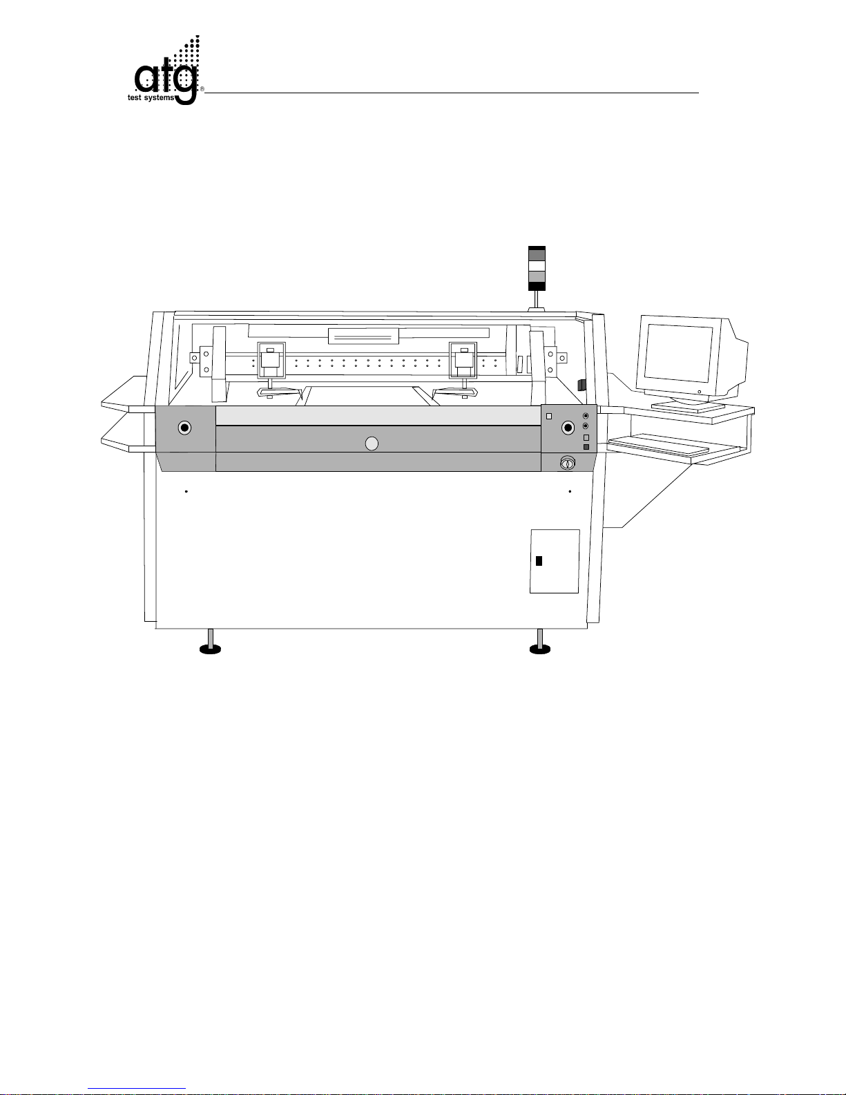
1.2 General View of the Test System
Fig. 1: General view of the A3 test system
1
3
4
5
6
7
8
8
9
10
12
2
11
2
2
Page 13

A-13
Test System A 3 V3.7
Position Description/Function
1 Main Power Switch (gray rotary switch)
Machine On/Off
2 Emergency Off
Machine Stop
3 Release of shuttle clamp (yellow button)
Release fine adjust for turning knob no. 10
4 Illumination controller top camera
5 Illumination controller bottom camera (option)
6 Control on (green button)
Machine control on
7 Control off (red button)
Machine control off
8 Flying probes with test needles
9 Shuttle
Ejectable board holding device
10 Signal Light
Indicates the machine status
11 Control Computer
The control PC is located behind this flap.
Page 14
A-14
Test system A 3 V3.7
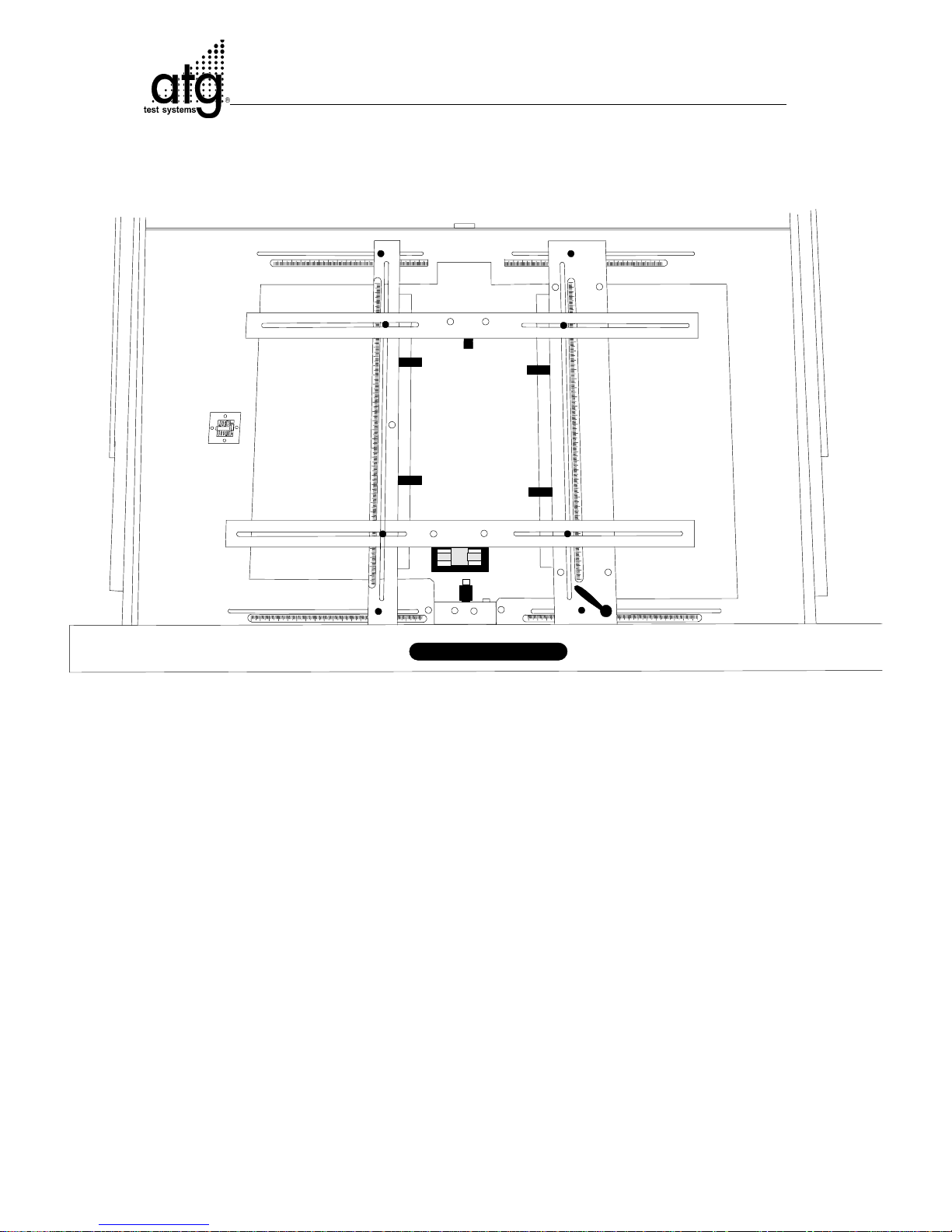
1.3 General View of the Shuttle
Fig. 2: General view of the A 3 shuttle
2
2
4
4
5
3
77
99
8
8
8
8
8
10
6
1
Page 15

A-15
Test System A 3 V3.7
Position Description/Function
1 Handle for shuttle
2 Fixing screws for left holder
3 Limit stop of shuttle
4 Fixing screws right Holder
5 Tension lever for lateral pressure
6 Spring loaded tense for head on pressure
7 Fixing screws for front holder
8 Clamp pieces
9 Fixing screws for rear holder
10 C-Adjust-Board
Page 16
A-16
Test system A 3 V3.7
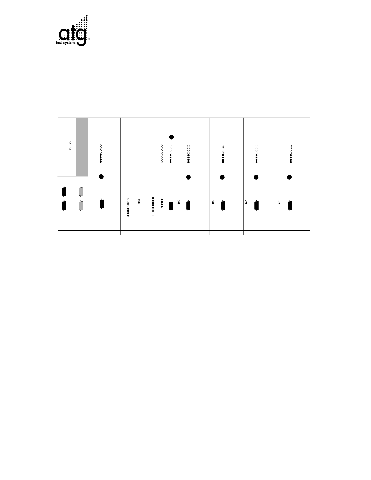
1.4 Assembly Rack
Fig. 3: Assembly racks
1 3 4 5 6 7 8 9a 9b 9c 9d
2
Page 17

A-17
Test System A 3 V3.7
Position Description/Function
1 Netcard for measure power supply ±15 V / 5 V
2 Extender-I/O-card
3 Head Controller / Motor Driver, Camera(s)
4 Measurement Controller
5 A_MUX (analog-multiplexer)
6 High voltage measuring card (HV 500), option
7 I/O-Controller (control card)
8 Crate Controller (main control card)
9a Head Unit / Motor Driver, Rail 0 (top, front)
9b Head Unit / Motor Driver, Rail 1 (top, rear)
9c Head Unit / Motor Driver, Rail 2 (bottom, front)
9d Head Unit / Motor Driver, Rail 3 (bottom, rear)
Page 18
A-18
Test system A 3 V3.7
1.5 Test Requirement for Repaired Boards
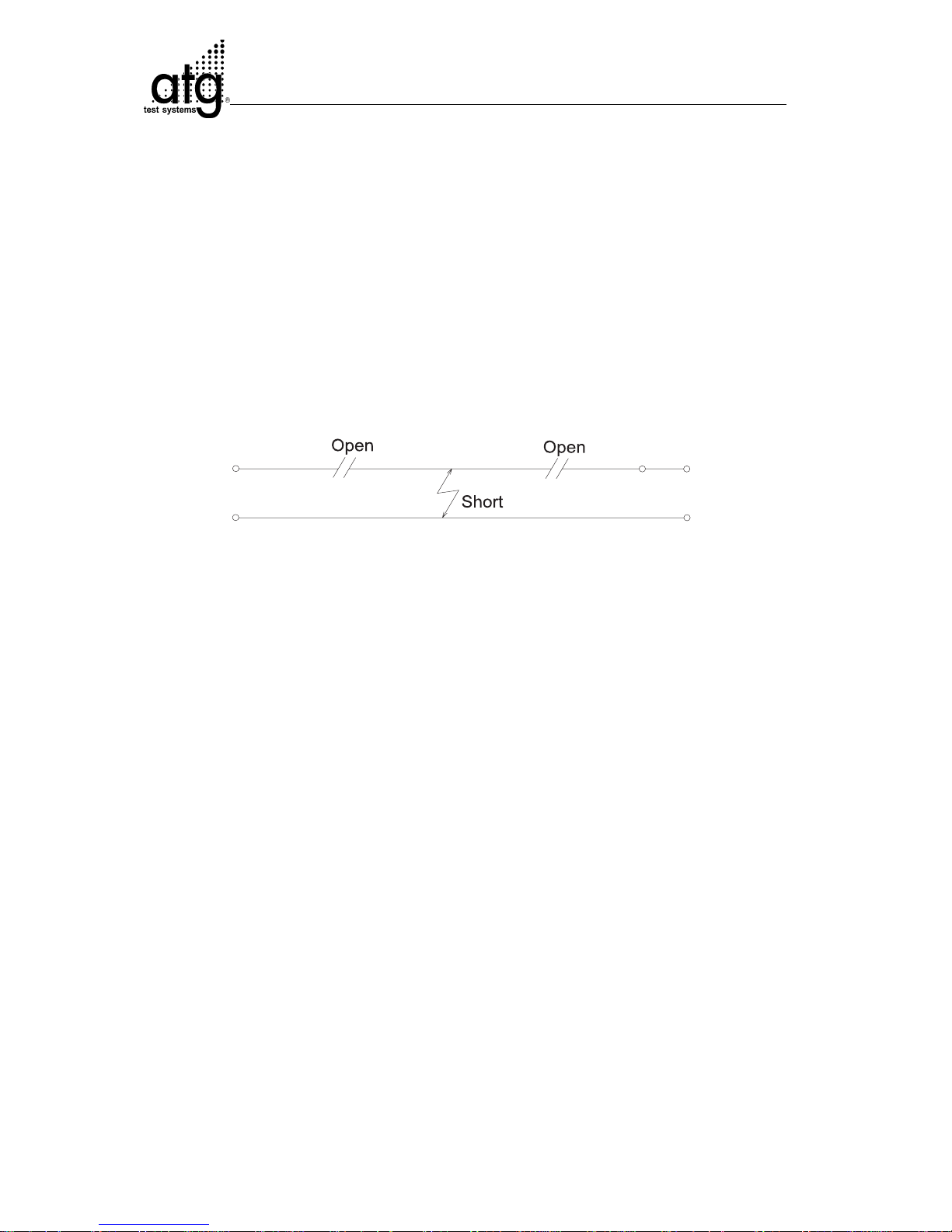
Boards tested faulty are often repaired and reused. Repaired boards must be retested
in a complete test.
Only a complete new test can give a correct good-result because there can be certain
fault constellations which can prevent the finding of all other faults (see figure).
Besides this, not all faults can be fixed with the repair or new faults may have
developed.
This does not depend on the applied test system or test method.
Page 19

A-19
Test System A 3 V3.7
1.6 The Operating Modes of the A3 Test
System
The Test Player, the control software of the test system, offers two different operating
modes:
1. The User Mode
is active directly after starting the Test Player. The user mode provides all basic test
functions, most parameters, however, cannot be modified in the user-mode.
The test runs are normally carried out in the user mode. During this, the possibilities
of the user are reduced so far that the test software may be learned quickly and applied
without having to experience great difficulties. The test parameters do not have to be
changed for the user mode, provided that the test parameters were appropriately
preset in the supervisor mode.
2. The Supervisor Mode
can be activated from the user mode by entering a password. In the supervisor mode,
you can adjust the basic settings, interrupt the test in progress or carry out controls.
Specially trained personnel must only activate the supervisor mode.
In this handbook, the user-mode and the supervisor-mode are extensively explained
and described.
Page 20
A-20
Test system A 3 V3.7
2. Turning on the Test System
1. Turn the Main Power Switch (Fig.1, No.1) to the On-position
The Control Off lamp (red key) is illuminated
The control PC boots
The fan of the control unit starts to run
2. Push the Control On-Key (green key)
The Control starts
The signal light shines red
The test probes carry out a short movement
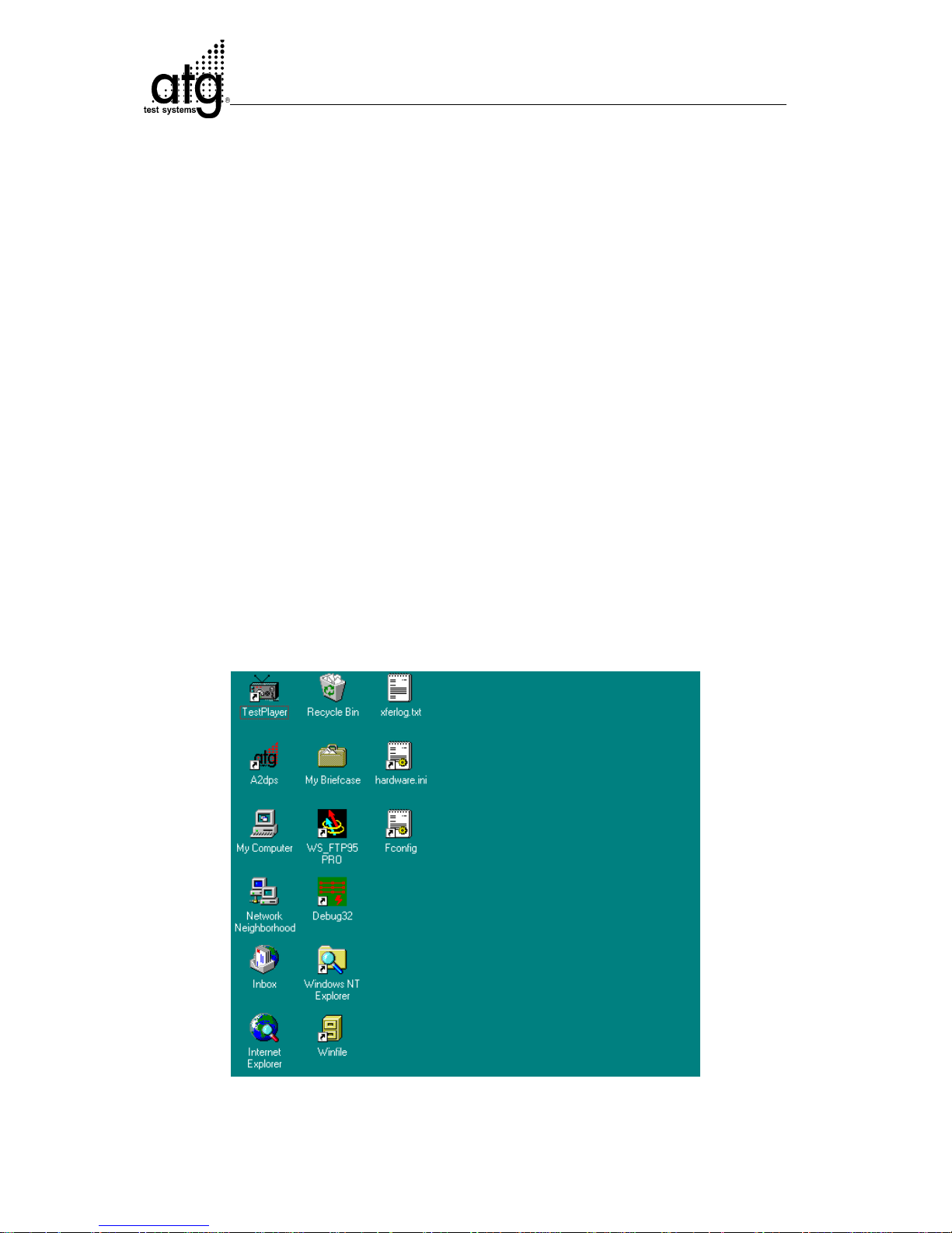
3. Start the
TestPlayer-
program
On the desktop, start the TestPlayer program by double-clicking its icon.
The operator program TestPlayer starts.
The icons on the desktop of the control PC
Page 21
A-21
Test System A 3 V3.7
The test system now loads different files and scans the hardware settings in a selfdiagnosis.
The signal light shines red.
The test system is initialized.
The test probes carry out a short movement.
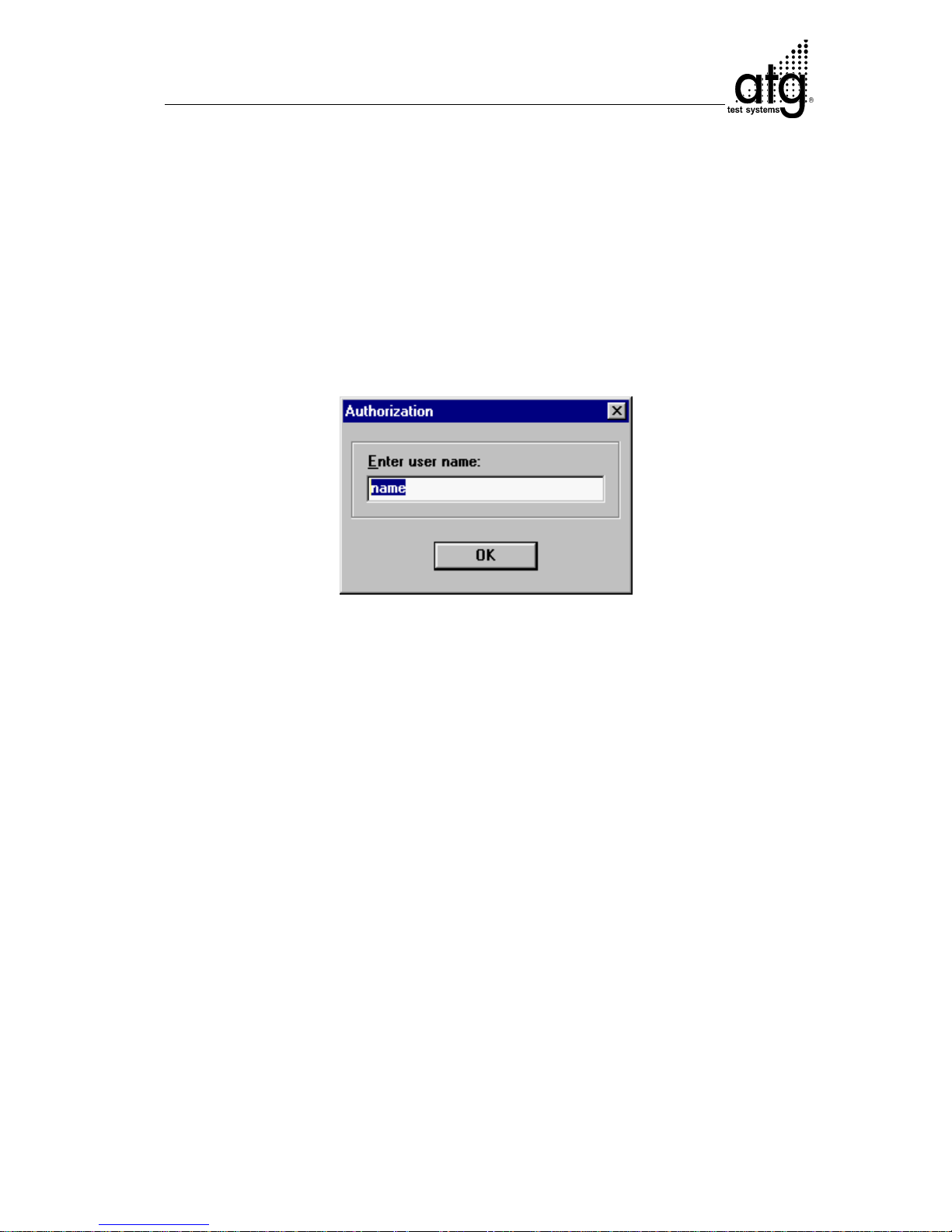
After having started the TestPlayer-software the input window Authorization
appears. Enter your name here. Your name is put out with the output of the test
results.
Entry of the user name
By pressing the OK-button after having entered at least one character you to enter
the main operating window of the user-mode.
Page 22
B-1
User Mode A 3 V3.7
3. The User Mode
3.1 The User Interface of the User Mode
Hint: Screen displays in this handbook may not be equivalent to the displays on your
monitor due to different software versions in use. However, this has no influence on the
descriptions of the functions.
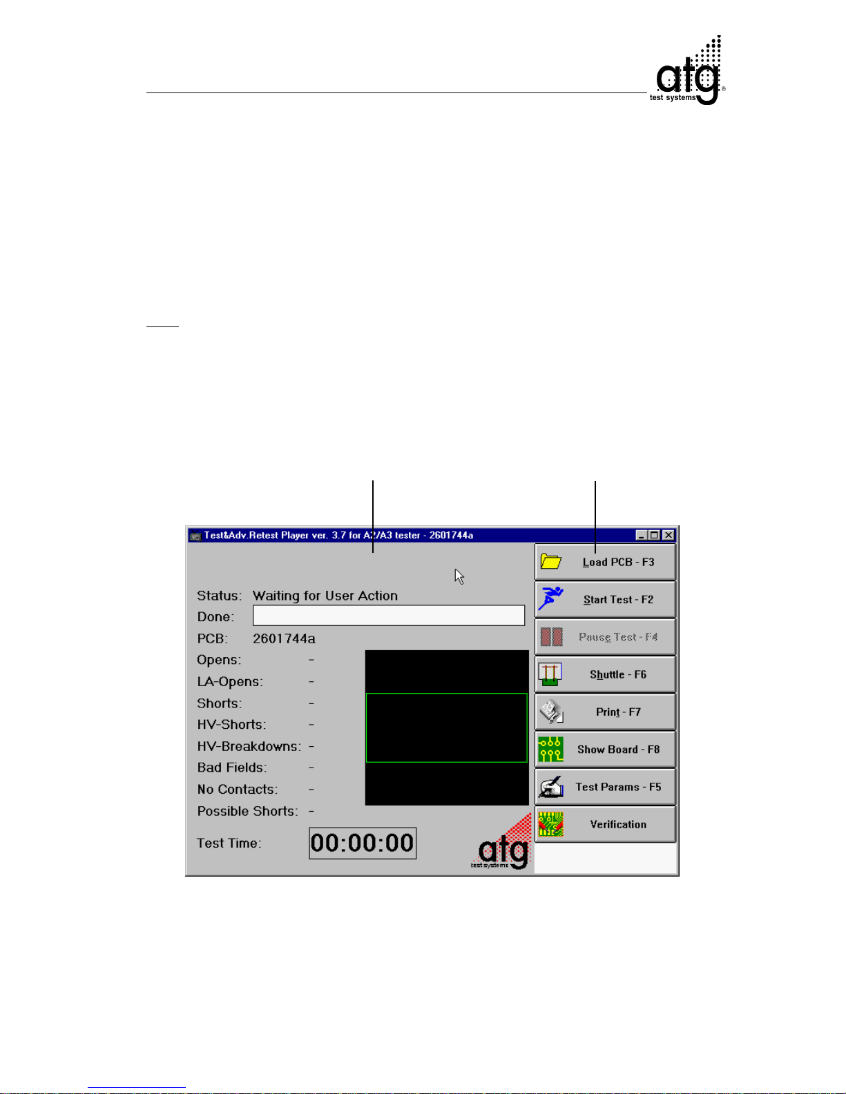
The user interface of the TestPlayer consists of two sections, the status field and the
buttons.
Status Field Buttons
The User Interface of the TestPlayer in the User-mode
Page 23

B-2
User Mode A 3 V3.7
3.1.1 Status Field
The left section of the TestPlayer-window shows the current test status.
The individual information lines in detail:
Status: Display of the currently executed function.
Done: Time bar indicating the test progress.
PCB: Name of the tested board.
Opens: Number of detected opens.
LA Opens: Number of detected LA-errors
(only with additional hardware)
Shorts: Number of detected shorts
HV-Shorts: Number of detected shorts in the high voltage test.
Only with additional hardware and with special data
preparation.
HV-Breakdowns: Number of detected breakdowns in the high voltage test.
Only with additional hardware and with special data
preparation.
Bad Fields: Unstable signals in the field measurement.
No Contacts: Test points not correctly contacted in the field measurement.
Possible Shorts: Number of detected possible shorts during the test run.
T est Time: Test time indication.
System messages are displayed in the status window left bottom side. Pay attention to this messages. They give exact informations about the state of the test
system.
Page 24

B-3
User Mode A 3 V3.7
3.1.2 Buttons
The buttons are located in the window’s right section.
A button can be activated either by clicking it with the mouse or by pressing the
appropriate function key (e.g. F3 for Load Board) indicated on the button.
Depending on the current test status of the T estPlayer , only certain commands are
available. An indistinct light gray font color indicates a currently unavailable command.
The functions of the individual buttons:
Button Function key Function
Load PCB F3 Load a new job
Start/Stop T est F2 Start/End the test
Pause T est F4 Pause the test
Shuttle F6 Lock/unlock the shuttle
Print F7 Print the test results
Test Params F5 Set test parameters
Find Pad F8 Move with camera or needle towards test pad
Step by Step F8 Execute testing in individual steps
Verification F9 Option. Only with dongle. Start of additional
programm "Verification" to verify faults found
in e-test..
Page 25
B-4
User Mode A 3 V3.7
3.2 Load job
In order to a test a new PCB you need to load its job (work data). Therefore, either click
the Load PCB-button or simply press the F3-key.
Hint: In order to execute a proper test run various prerequisites must be met described
in the Chapter Supervisor Mode (e.g. calibration, C-Adjust, etc.)
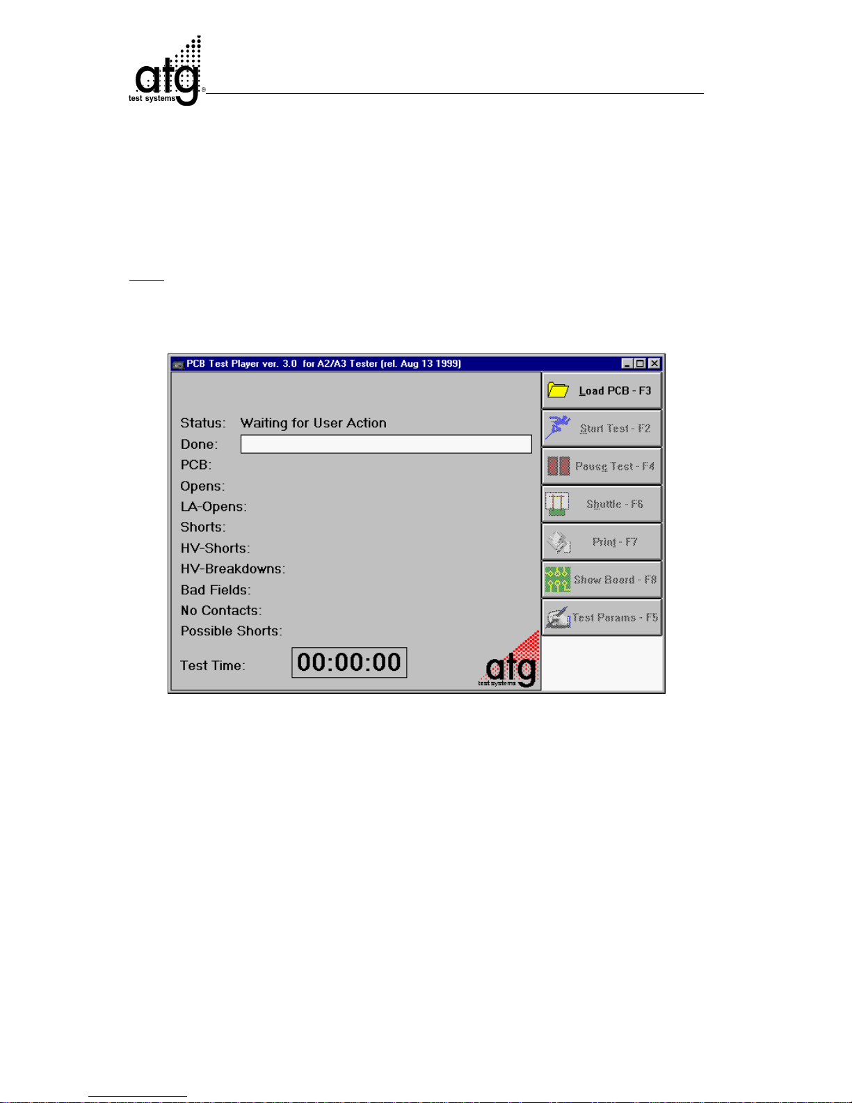
PCB test player
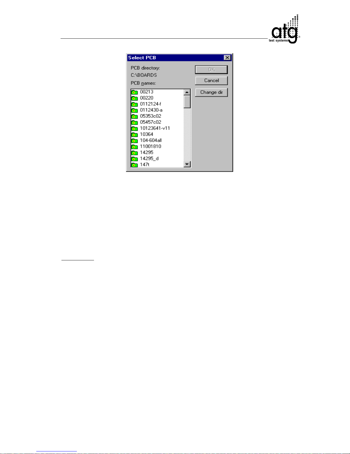
The window Select PCB appears.
Page 26
B-5
User Mode A 3 V3.7
Selection-window Select PCB
From the given list load the desired job. In order to select a job you can either use the
scrollbar on the right side of the window and click on the desired one or you can jump
to the job’s first letter by using the keyboard (e.g. Enter ”e” for EL323 or enter ”3” for
34abc). The selected job appears highlighted.
With the button Change dir you load test data from a different folder, hard drive or from
a connected network. Therefore, a second path must be entered into the configuration
file fconfig.ini of the TestPlayer.
Annotation: Each job has its own folder containing the test-required files. For a
successful test, the job folder must contain the 4 following files:
*.ant antenna-file e.g. name.ant
This file contains information on the antennas.
*.les net list-file e.g. name.les
This file contains the board’s net list.
*.tsk task-file e.g. name.tsk
This file contains the commands for the individual test probes.
*.vw view-file e.g. name.vw
This file contains the info on the board’s position in the test system as well as
information about the scanmarks.
A job including these four files is displayed as a green folder. A brown folder
indicates an unloadable job. (Reason: a file is missing, the name conventions are
not met or the DPS did not completely process the job.)
The file *.adj (e.g. name.adj) is also included in the job if with the DPS-software
created an adjacency-file.
The board’s test data are loaded. Now you can set up the test system for the board.
Page 27
B-6
User Mode A 3 V3.7
4. Adjusting to a New Board
4.1 Ejecting the Shuttle
Now set the board into the shuttle. Therefore, open the shuttle locking-mechanism by
clicking on the Shuttle-button (F6). You will hear a clicking. Manually pull out the
Shuttle out of the machine until the locking-mechanism automatically engages in the
outer position. You will once more hear a clicking.
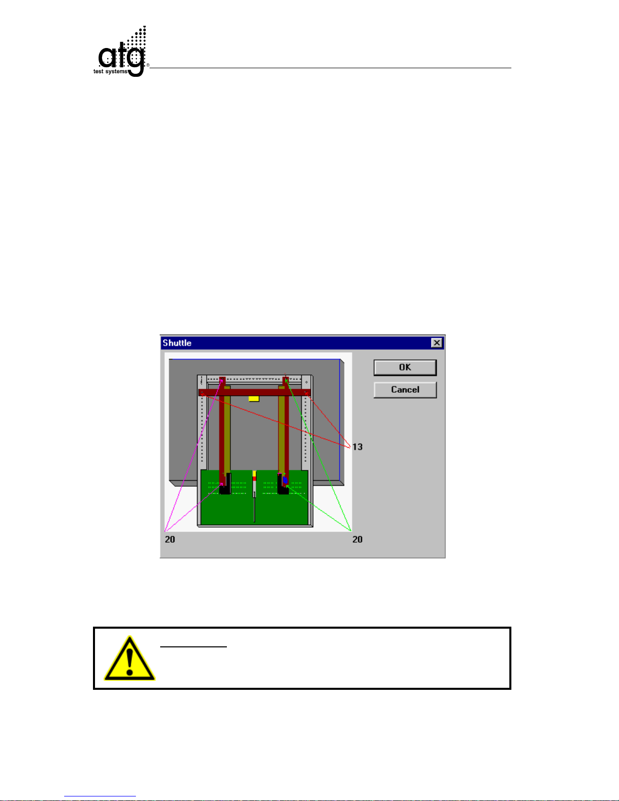
The window Shuttle appears. It shows the pre-defined placing of the product holders,
which fasten the board.
Window Shuttle displaying the placement data for each holder
Attention: The shuttle must not be mechanically
stressed in the open position, i.e. it is forbidden to lean
on or place any other objects on it!
Page 28
B-7
User Mode A 3 V3.7
Annotation: The shuttle can be unlocked in two different ways:
1. If the TestPlayer’s main-window is open, unlock the Shuttle by clicking the Shuttle-
button (F6).
2. If the Shuttle-window is open, unlock the Shuttle by clicking OK. The Shuttle will
not be unlocked if the Cancel-buttons clicked. Only the Shuttle-window is closed
that way.
4.2 Adjusting the Product Holders
4.2.1 Selecting the proper Terminal Bar Sizes
Place at least two terminal pieces on each the left and the right product holder, and
one terminal bar each on the front and rear product holder (Fig. 2, No. 8). The
connecting surface must point downwards and the terminal bars must clamp in.
The following applies to the terminal bar selection: As small as possible, however
not smaller than the board thickness.
All holders must be set in a right angle.
If you would like to see how the board is to be set into the shuttle you can view its
required position in the shuttle with the button Show Board (F8).
Observe that the contact pads located on the
board’s edge are not covered by the terminal bars
(especially on the solder side) and that the terminal
bars are not to close to them, since otherwise
faulty measurements or damages to the test heads
might result! In such a case, replace the terminal
bars.
Page 29
B-8
User Mode A 3 V3.7
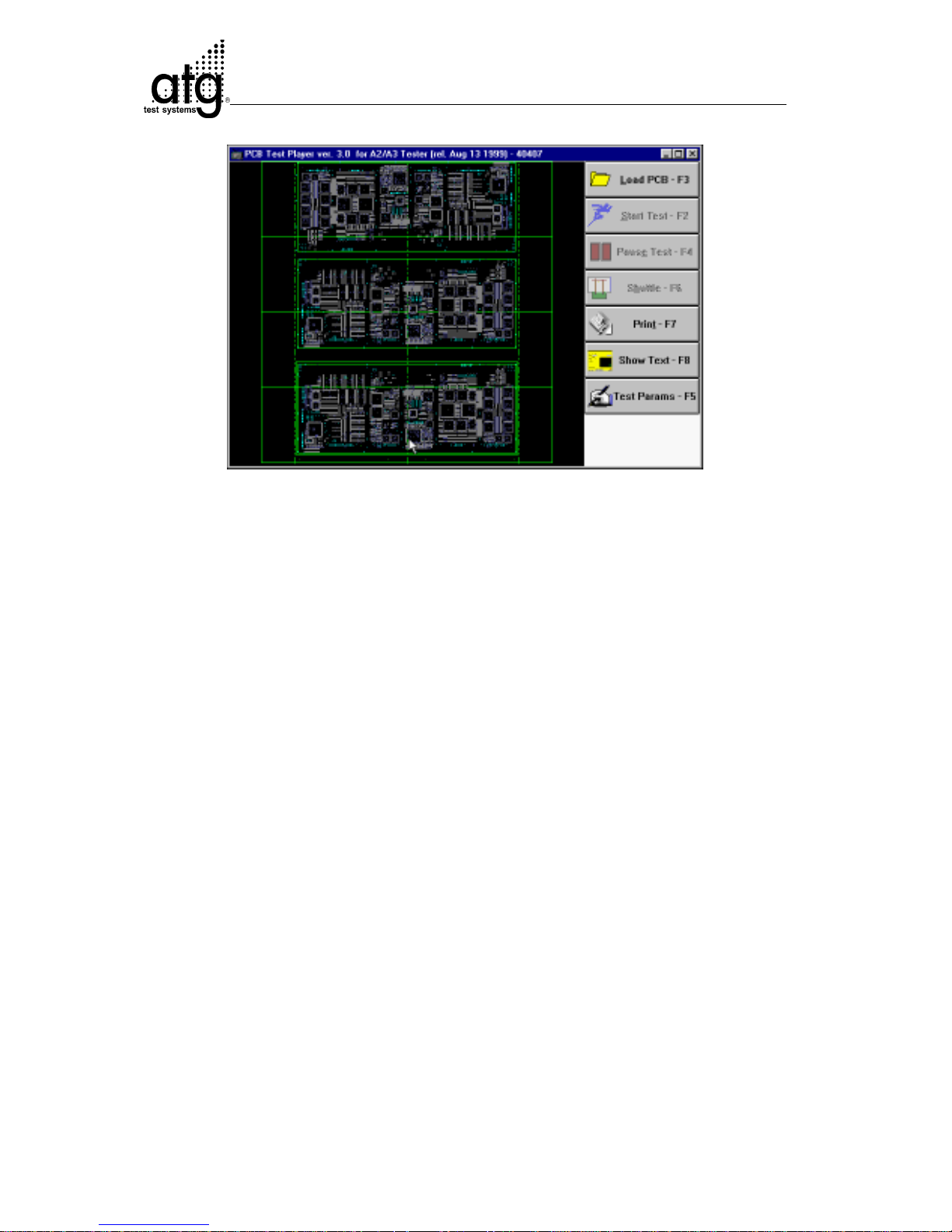
Display of the board position in the shuttle with the button Show Board (F8)
Re-clicking the Show Text (F8)-button returns you to the working window.
In the window Shuttle (F6) the loaded board file displays the required positions of
the product holders.
The example figure page B-6 indicates that the left product holder must be set to the
scale position 29 and the rear holder to position 19.
Small arrows indicate the scale position.
4.2.1.1 Adjusting the left product holder
Open both clamp screws (Fig. 2 No. 2) of the left holder and adjust the product holder
to the required position on the positioning scale. Re-tighten both clamp screws.
4.2.1.2 Adjusting the rear product holder
Open both clamp screws (Fig. 2 No. 9) of the rear holder and adjust the product holder
to the required position on the positioning scale. Control the position of the rear
terminal bar by holding the board against the adjusted position.
Re-tighten both clamp screws.
4.2.1.3 Adjusting the right product holder
Open both clamp screws (Fig. 2 No. 4) of the right holder and set the clamping lever
(Fig. 2 No. 4) all the way to the right.
Page 30

B-9
User Mode A 3 V3.7
Lay the board on the surfaces of the terminal bars of the left and rear holder and push
the right holder against the board until it is safely fixed. Pay attention towards proper
board positioning!
Re-tighten both clamp screws of the right holder.
4.2.1.4 Adjusting the front product holder
Tighten the clamping device (Fig. 2 No. 6). Open both clamp screws (Fig. 2 No. 7) of
the front product holder. Push the front product holder towards the board leaving
approx. 1 mm distance between the clamping device and the board.
Re-tighten both clamp screws of the front holder.
Loosen the clamping device.
Pay attention towards a proper fit between all terminal bars and the board.
Loosely clamp the board laterally with the clamping lever (Fig. 2 No. 5).
4.2.1.5 Inserting the Shuttle
After the board is properly fastened the shuttle can be driven into the test system.
Release the locking mechanism by clicking on the OK-button in the Shuttle-window
or by pressing the Return-key.
The Shuttle-window closes and the locking mechanism is released (you will hear a
clicking). Click the Cancel-button if you do not want to release the shuttle locking
mechanism. This way only the Shuttle-window is closed.
If the Shuttle-window is not open, push the F6-key or click on the Shuttle-button.
Push the Shuttle into the system until the locking mechanism engages again (you will
hear a clicking).
Page 31
B-10
User Mode A 3 V3.7
5. Starting a Test in User Mode
You can begin testing after the board adjustment is complete and the shuttle is in the
system.
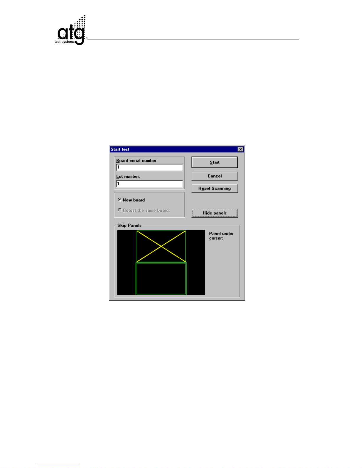
With the mouse, click the Start Test-button (F2). The input window Start test appears.
Input window Start test
Enter the serial number of the board into the Board serial number-field. In the field Lot
number the individual lots are automatically numbered. Confirm your entry with the
Start-button.
With the button Show panels you can - for multi panels exclude - exclude individual
panels from the test. The small graphic in the window schematically illustrates all
panels. If the cursor is above a panel its number is displayed underneath the text line
Panel under cursor. Click on the panels to be excluded. The excluded panels are
displayed crossed out.
You can exclude a larger number of panels at once from testing by dragging the mouse
with the left mouse-button being simultaneously pressed over the entire panels to be
excluded. A white filed extends over these panels. All panels touched and covered by
this white field are excluded from testing or reincluded for the test.
Page 32

B-11
User Mode A 3 V3.7
Annotation:
For testing a new lot its automatically pre-assigned lot number should not be changed.
If you wish to assign a lot a specific number enter the desired number into the lot
number-field.
The button Retest the same board is only activated if a board had already been
tested. Use this button for testing the same product once more. The run-number will
not change.
Page 33
B-12
User Mode A 3 V3.7
5.1 Button Test Params (F5) in the User
Mode
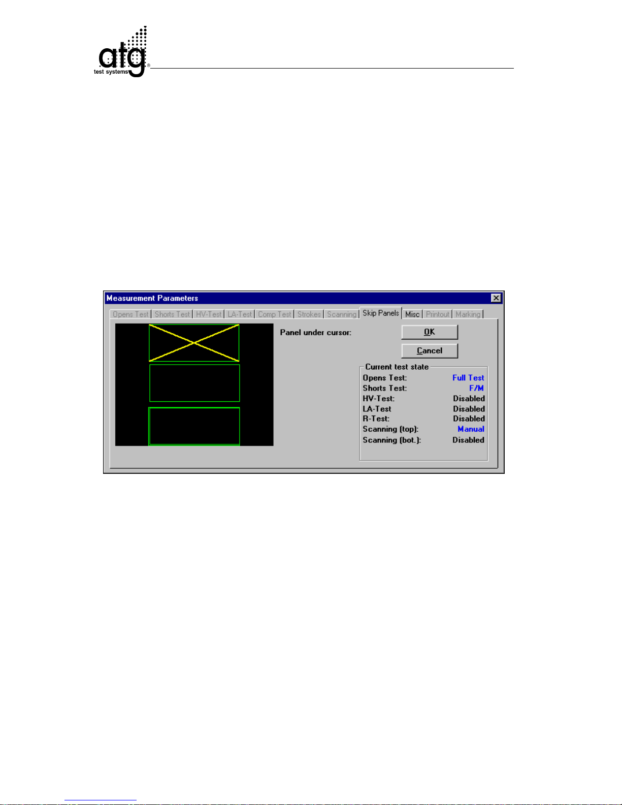
In the User mode there are under button T est Params (F5) two tab-boxes available:
Skip Panel and Misc.
5.1.1 Tab-box: Skip panels
Panel selection window
For multi-panel testing, you can exclude individual panels from testing with the Test
Params (F5)-button. For this purpose use the Skip panels-menu.
The small graphic in the window schematically illustrates all panels. If the cursor is
above a panel its number is displayed underneath the text line Panel under cursor.
Click on the panels to be excluded. The excluded panels are displayed crossed out.
You can exclude a larger number of panels at once from testing by dragging the mouse
with the left mouse-button being simultaneously pressed over the entire panels to be
excluded. A white filed extends over these panels. All panels touched and covered by
this white field are excluded from testing or reincluded for the test.
Page 34
B-13
User Mode A 3 V3.7
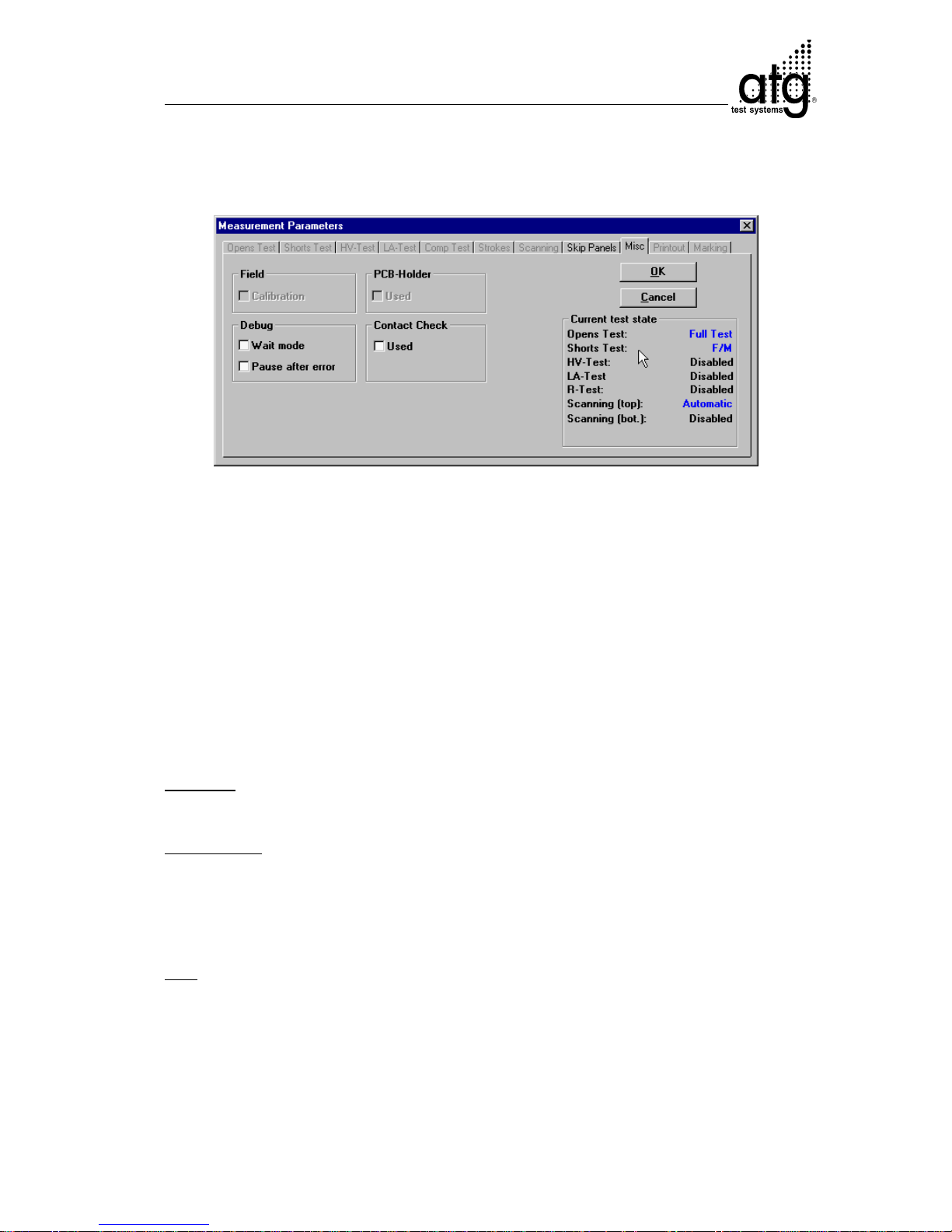
5.1.2 Tab-Box: Misc
Tab box: Misc
Field
Not functional with test system A3.
Debug / Wait mode
Perform testing step by step. Motions and measurements of the task file are sequentially executed. Consequently , the test speed is reduced facilitating the analysis of the detected faults.
The reduced test speed enables the reading the status window, giving information
about the test run.
Example:
Resistance 2 <-> 3 [5 <-> 385 / 3]
Explanation:
A resistance measurement was executed with the probes 2 and 3 between the
point Ids 5 and 385 of panel 3.
Wait mode is enabled if it is checked off in the pull down menu.
Hint:
Wait mode can be turned off during the test leading to its continuation at regular
speed.
Page 35

B-14
User Mode A 3 V3.7
Debug / Pause after error
Interrupt testing (identical to Pause T est (F4)). Pause after error, only discontinu-
es testing if a fault (open or short) is detected. The button Pause T est (F4) switches
to Resume Test (F4).
The message ”Test Paused” appears. Resume Test (F4) continues testing.
At normal test speed, the application of this function is senseless since the test
system must first process its command buffer (up to 200 commands) before it can
respond to the Pause command.
Hint:
In Wait mode (main menu Debug / menu item Wait mode), you can pause the test
exactly at the desired position. Apply the combination of Wait mode and Pause
after error for debugging. Pause after error is enabled if it is checked off in the pull
down menu.
PCB-Holder / Used
Applies the maximum Z-axis stroke value. (The maximum value is specified in the
tab box Stroke, function Z-up.)
The minimum Z-axis value, pre-set by the test system (see tab box Strokes: min
up value), amounts to 1/3 of the defined Z-axis stroke. For increasing the test
speed, the Z-axis stroke is reduced to the min up value if the board topography
allows this. This option is disabled by checking off PCB-Holder / Used.
For multi-samples, the parameter PCB-Holder / Used should always be set to
Used since the boards can be pushed to the bottom or top due to the holder
pressure, possibly damaging the test probes or the board might result. Furthermore, select Used if specially built holding systems for flexible boards are applied.
This excludes contacts between test probes and the holding system.
Page 36
B-15
User Mode A 3 V3.7
5.2 Scanning (Determining the board
position with the camera)
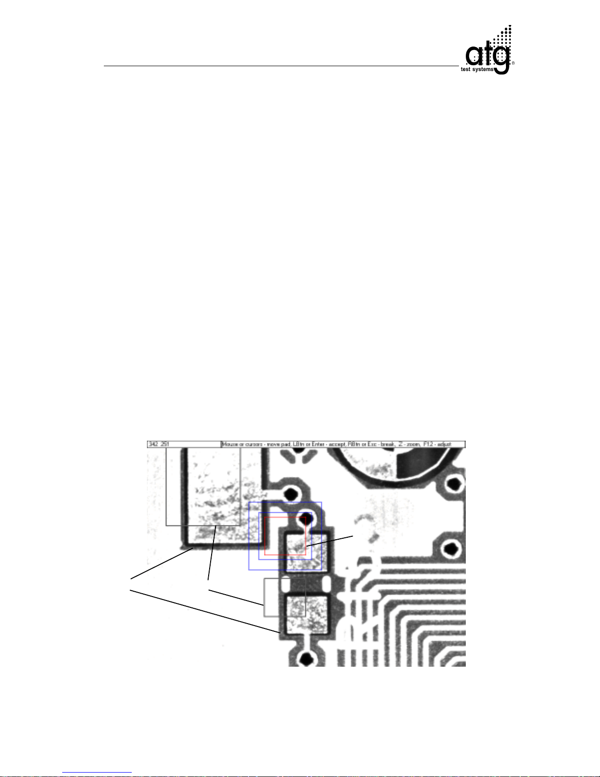
The first step in the test procedure is the scanning. Due to the mechanical tolerances, the individual boards always show a slight difference between their actual
position in the shuttle and their required position defined by the test data. This
offset between actual and required board position must be determined through a
measurement in order to be corrected by the test system.
For determining this offset, the board is scanned by one or two cameras. During
this procedure, the camera scanmarks from the test data are brought to congruence with a section of the board.
If the camera picture is not exactly positioned on the scanmarks, they must be
properly positioned to the correct camera picture with the mouse or with the cursor
keys. Confirm this position with a left mouse-button click.
The red scanmark is decisive for the placement. The yellow scanmarks serve as
an orientation. Compare the entire scanmark structure to find out whether the
correct position was achieved.
The learned scanmark position is automatically considered and scanned for the
following automatic test.
Example for incorrect placement of scanmarks:
red scanmark and black camera marks have not the position on the pads
Red scan mark
Camera marks
Board marks
Page 37
B-16
User Mode A 3 V3.7
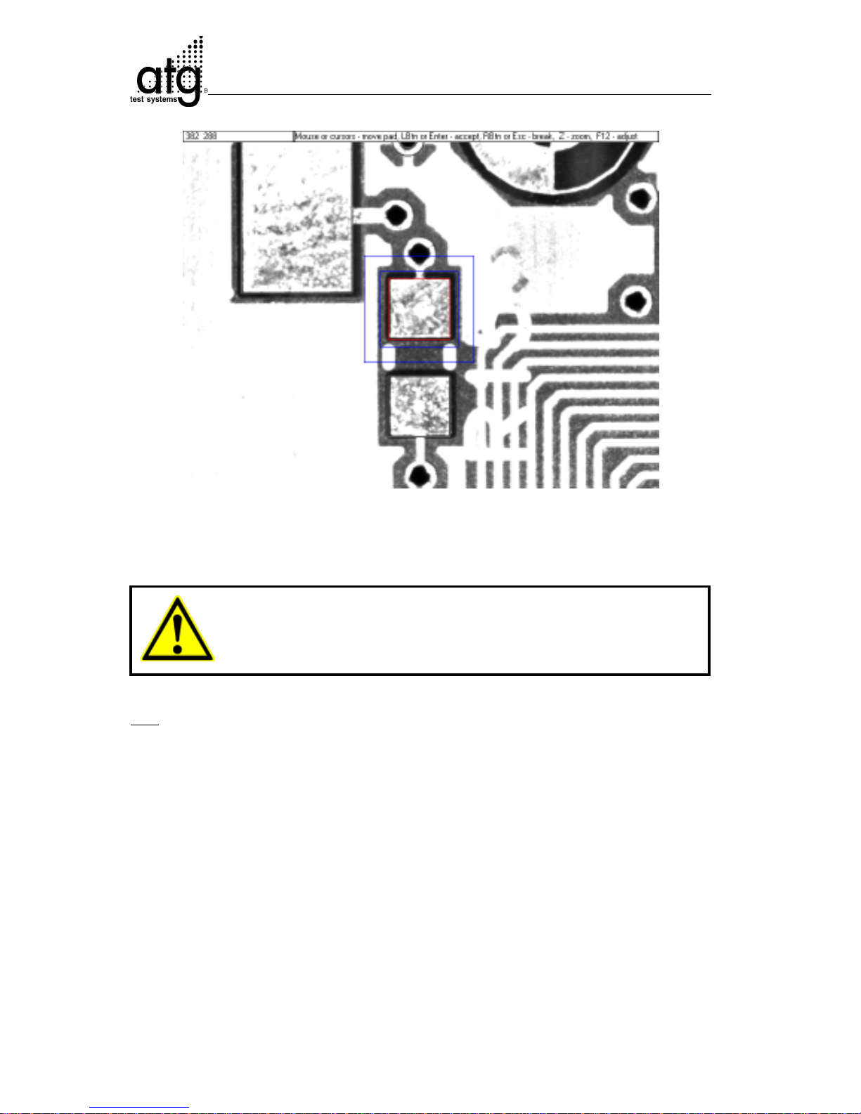
Example for correct placement of scanmarks:
red scanmark and black camera marks have their position exactly on the pads
Hint:
possible causes of board and camera scanmark incongruence:
- board improperly fixed
- wrong board fixed
- net list contains no or false board contours
The scanning procedure can be canceled with the right mouse-button or the Esc-key.
A board without fine structures requires the scanning of only one side. A great offset
between the top and bottom layer (frequently for multi-layered boards) requires the
scanning of both sides.
Attention: Position the red scanmark exactly on the
corresponding pad of the camera picture!
Page 38
B-17
User Mode A 3 V3.7
5.2.1 Manual scanning
Every scanmark must be placed manually if manual scanning was set in the supervisor
mode.
Every time you move a scanmark with the mouse in order to place it, the scanmark is
automatically moved to the screen center after the mouse click. A second mouse click
confirms its new position.
The camera automatically moves on to the next scanmark if the scanmark position is
not changed. Otherwise, the scanmark needs to be re-placed again.
Hint: A test is canceled after the scanning procedure, if the scanmark position
expected by the test system differs more than 5 mm in x-direction or 3.5 mm in ydirection from the actual position. The following message appears:
The following errors might exist:
- Board improperly fastened
- Wrong board inserted
- Net list contains no or false board contours
After a successful scanning testing is started automatically.
For multi-panel testing, it may occur that one section of the multi-panel is located within
the shift tolerance while the other one is not. In this case, the panels located outside
of the shift tolerance are automatically excluded from the test. The window Scanning
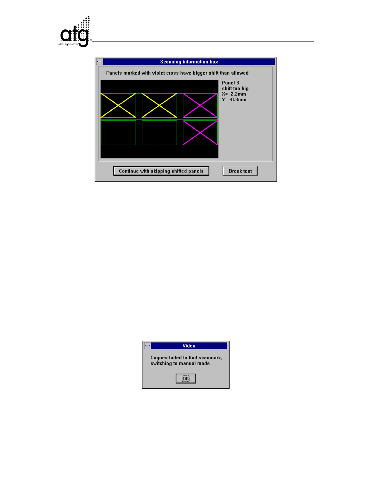
information box appears:
Attention: The decisive red scanmark of the camera
must be exactly positioned on the concerned pad of
the board.
Page 39
B-18
User Mode A 3 V3.7
The skipped panels are crossed-out. Panels marked with a violet cross show a bigger
shift than allowed. The purple crossed-out panels show a too large offset. The shift of
an individual panel is shown in the right if the mouse positioned on it.
Inspect the possible reasons for a big shift.
You can continue testing the remaining panels (with the button Continue with
skipping shifted panels) or cancel the test (Break test-button).
5.2.2 Automatic scanning
For automatic scanning enabled in the supervisor mode, only the scanmark of the first
board of a series must be placed with the mouse. The test system learns this position
and automatically sets this scanmark position on the following boards of this series.
Testing is started automatically after the scanning process was successfully completed.
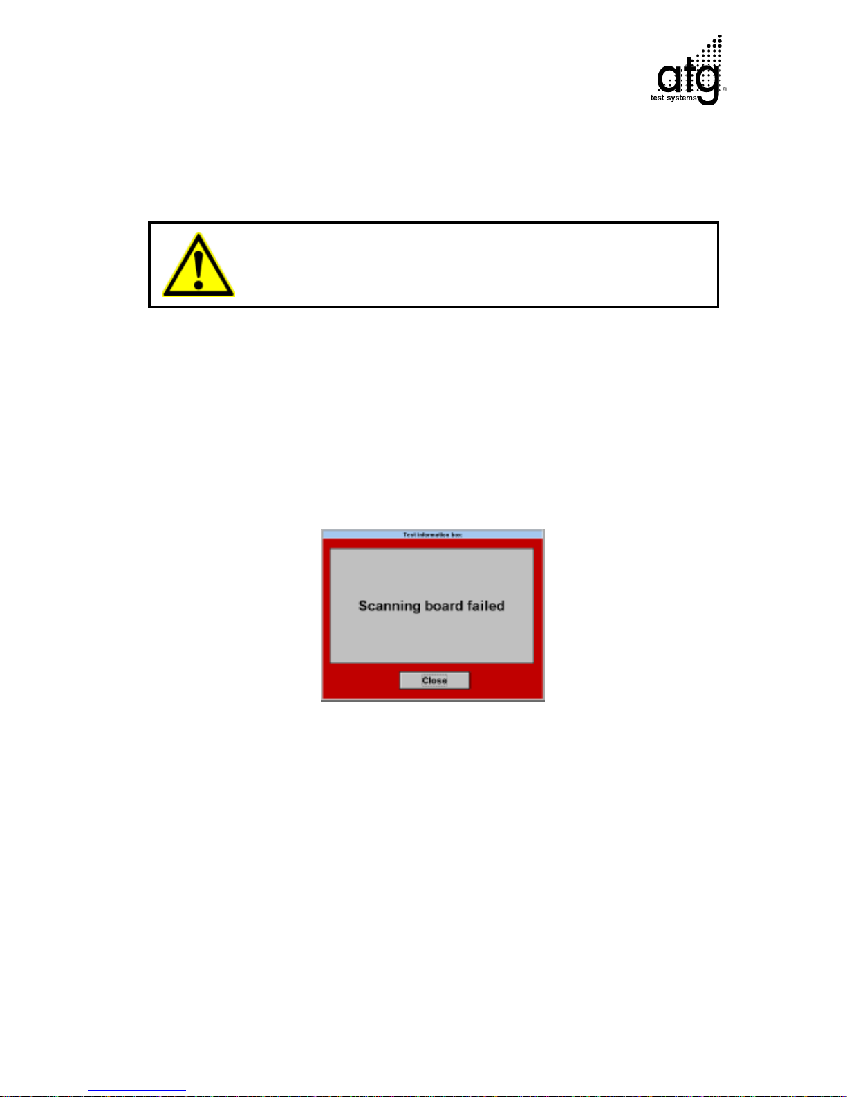
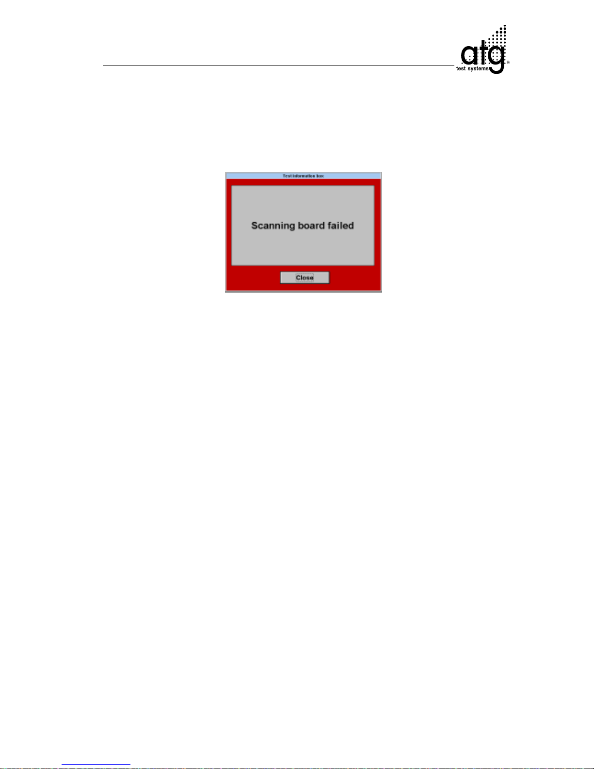
The following window is displayed, if the automatic scanning happens to fail:
Close this window with the right mouse-button. The scanning procedure must then be
continued manually. The scanning is only automatically continued if the test system
recognizes the position of the next scanmark.
Every time the board data is newly input, the scanmarks must be relearned.
Page 40
B-19
User Mode A 3 V3.7
5.2.3 Wrong Board Position
The scanning procedure is canceled if the test system detects a too big offset between
the actual scanmark position and the one given in the test data. The following warning
is displayed:
In this case, check the following:
- Product holders properly adjusted?
- Board properly inserted?
- Step&Repeat incorrectly applied? (first panel scanned correctly, the following
faulty)
- Wrong pad considered as scanmark?
- Do the test data differ from the original board?
Restart the test after these corrective measures.
5.2.4 Canceling the scanning process
Scanning can be canceled at any time by clicking the right mouse-button or by
pressing the Esc-key . In this case, the board is not tested.
Page 41
B-20
User Mode A 3 V3.7
5.2.5 The Beginning of the Test
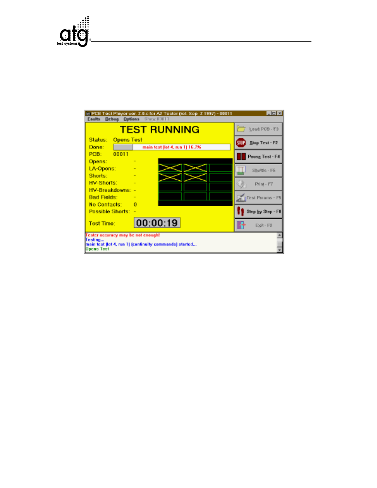
The test system automatically starts the test run after the scanning. The line TEST
RUNNING flashes and the board faults and the test time are displayed.
Test running
5.2.6 Pausing and Resuming a Test
Click the Pause-button (F4) to pause testing. The test system comes to a stop in
approx. 3 seconds after the command buffer is fully processed.
Testing is continued from the point where it was halted by clicking the Resume testbutton (F4).
5.2.7 Canceling the test
Click the button Stop (F2) to cancel testing. In this case, no test results are recorded.
Page 42
B-21
User Mode A 3 V3.7
5.3 Test Result Output
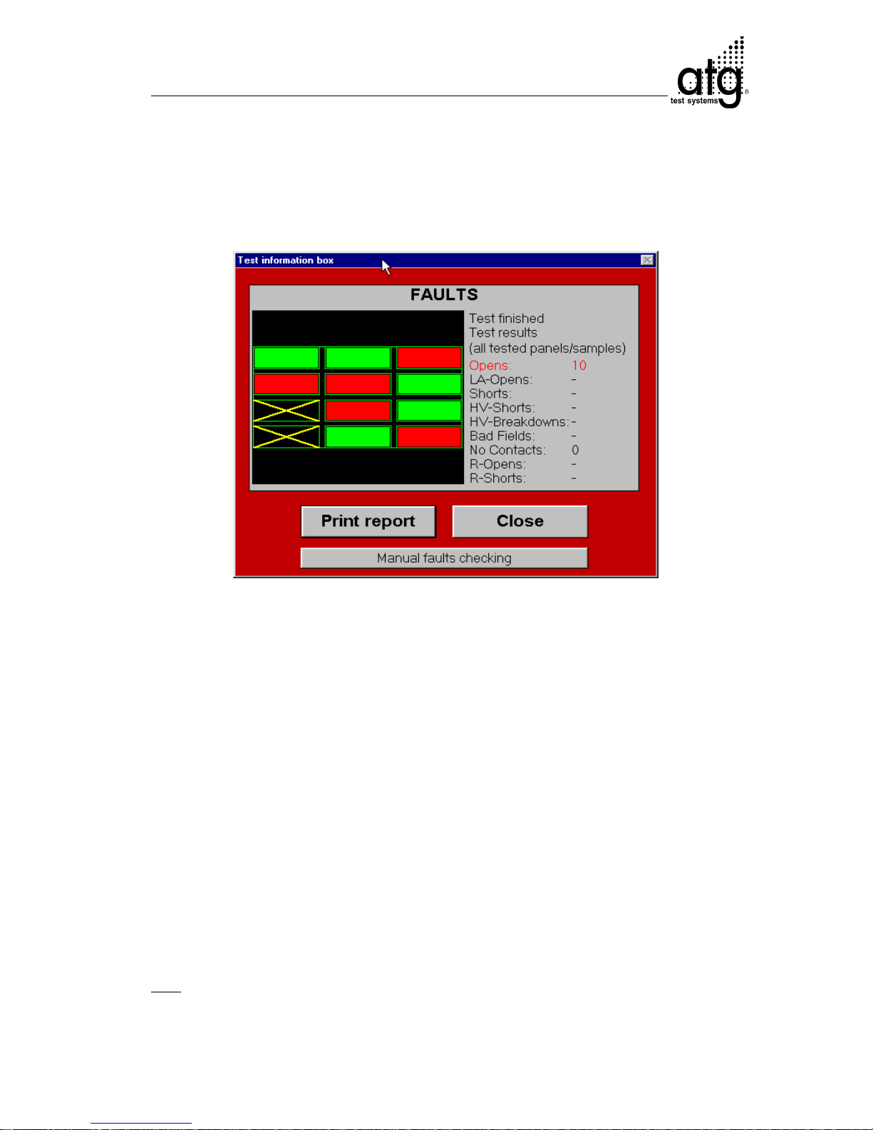
After a test run is completed, the test results are put out in the Test information box.
Test results
In the shown board view, faultless panels are displayed green and faulty panels
red. Panels excluded from testing are crossed out yellow.
Panels automatically excluded after scanning by the test system are displayed
violet. This for example occurs if the Step&Repeat-command is incorrect or if the
board presents a too great offset.
In the fault list, all faults are listed in red.
Placing the cursor on a tested panel displays only its individual faults in the faults
list.
Push the button Print report to activate the output option selected in the supervisor
mode with the button T est Params (F5). The button Close exits the Test informa-
tion box.
The test results can be printed at any time by pressing the button Print (F7).
However, if the test data was modified, a test result output with the button Print (F7)
is no longer possible (Error message: Wrong Timestamp)
Depending on which output option was selected in the supervisor mode, the test
results are put out on screen, printed or saved as a file.
Hint: The printer driver is installed under Windows.
Page 43
B-22
User Mode A 3 V3.7
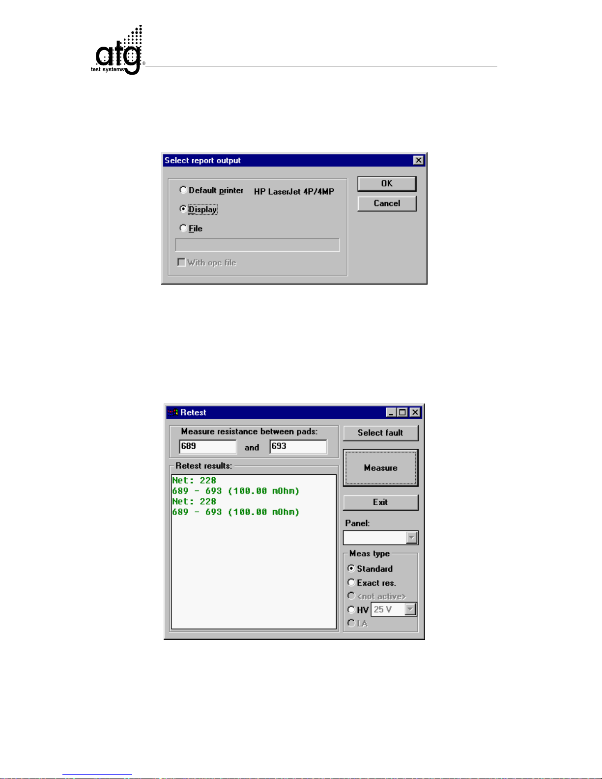
The setting Ask before printing of the supervisor mode allows the user to select the
kind of output. Therefore, the window Select report output is displayed. Here, the test
results can also be put out in several variants after each other.
Output selection via ”Ask before printing”
The button Manual faults checking offers the option of selectively retesting individual
faults. The window Retest is opened after this button is activated. This function only
supports sequential single measurements. With it, you can carry out a retest of the
ohmic resistance between faulty test pads.
Select retest pads
Page 44
B-23
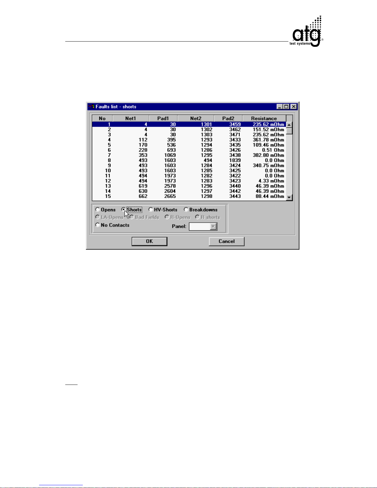
User Mode A 3 V3.7
With the button Select fault of the Retest window, you can select and retest both
pads of a single fault from the loaded faults list. The Faults list window is opened
for selecting a fault retesting with a double-click.
In the bottom section of the window, select the type of faults to be retested (Opens,
Shorts etc.).
The contacting of both faulty pads is carried out in a „stand-by mode“, i.e. the test
heads slowly approach the pads, contact them for 5 seconds and then remain
above the contacted pads. This enables an exact analysis of the individual measurements via the contact position.
Unconfirmed retested faults are displayed green in both the Faults list and the
Retest windows. Confirmed faults are again displayed red.
In the fields Measure resistance between pads, it is also possible to enter the IDpads between which the resistance value is to be determined. The Measure button
initiates the desired test. The measurement value is displayed in the Retest
results-window.
Hint:
The option Exact has no function.
Page 45

B-24
User Mode A 3 V3.7
6. Removing the tested Board
and inserting a new One
After a board was tested and its results were put out a new one can be inserted. For
this purpose the shuttle can remain in its inserted position.
Open the shuttle locking and pull out the shuttle. Relax the board by opening the
tighting lever (fig. 2, no. 59) and unlock the spring loaded tighting element (fig. 2, no
6). Now you can take out the board.
Put in a new board and close the shuttle by pressing the button Shuttle (F6). Now you
can test the new board.
6.1 Turning off the Test System
Hint:
To guarantee a flawless test, the test system should never be switched off. If you don't
use the test system for a longer time, the monitor can be switched off.
The test system is cooling down after turning off and the accuracy is reduced until the
working temperature is restored.
1. Press button Control off (p. A-12 no. 7, red Button)
After 4 seconds all control rack LEDs switch off.
2. Turn main switch to off (p. A-12 no. 1).
Page 46
C-1
Supervisor Mode A 3 V3.7
7. The Supervisor Mode
7.1 Introduction
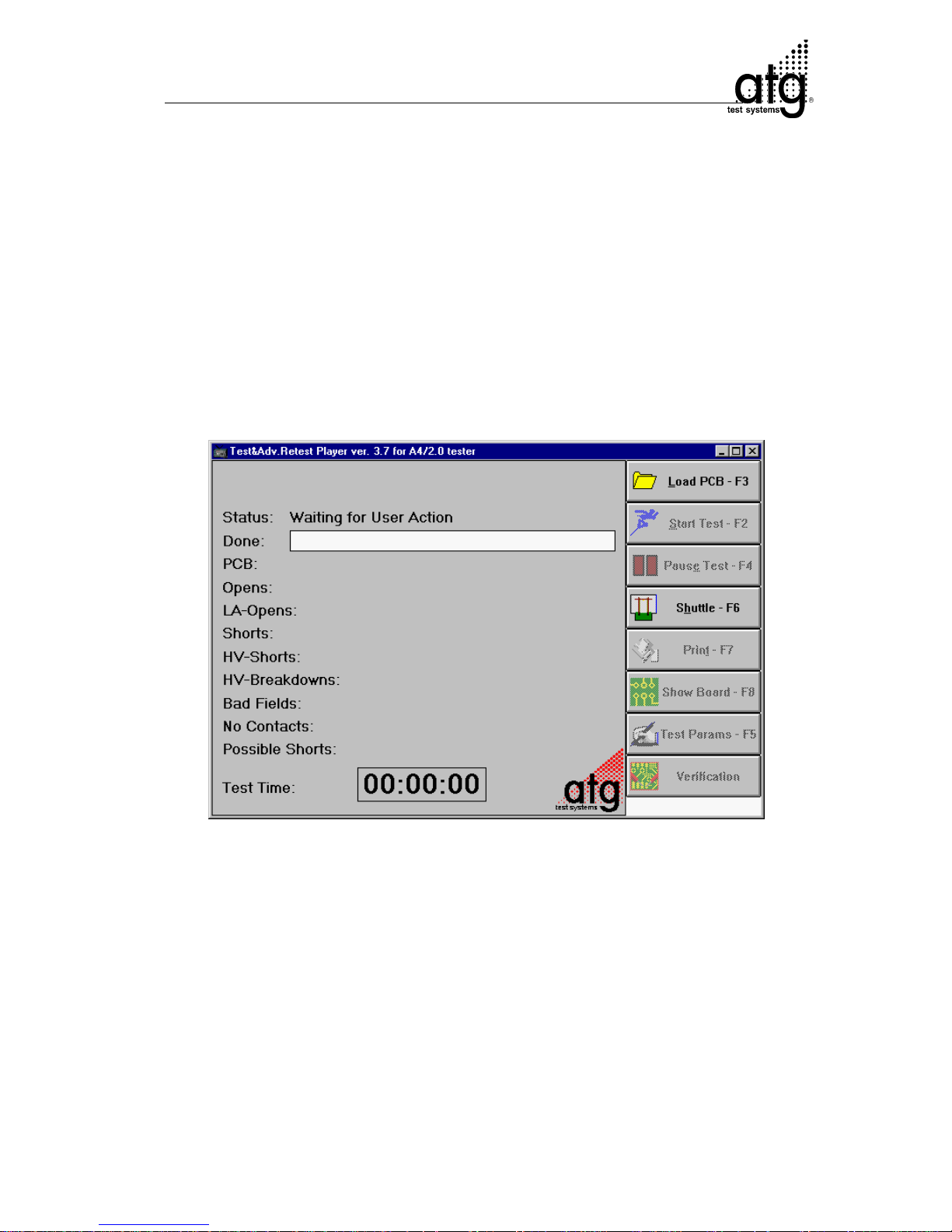
After starting the Test Player-program you are in the user mode. The user mode
provides you with all necessary basic functions for the circuit board test.
The Test Player in the user mode
From the user mode, you can activate the Supervisor-mode through a password. The
supervisor mode provides additional functions enabling the adjustment of basic
settings, test interference or the execution of inspections.
Appropriately trained operators must only activate the supervisor mode.
Page 47
C-2
Supervisor Mode A 3 V3.7
7.2 Switching to the Supervisor Mode
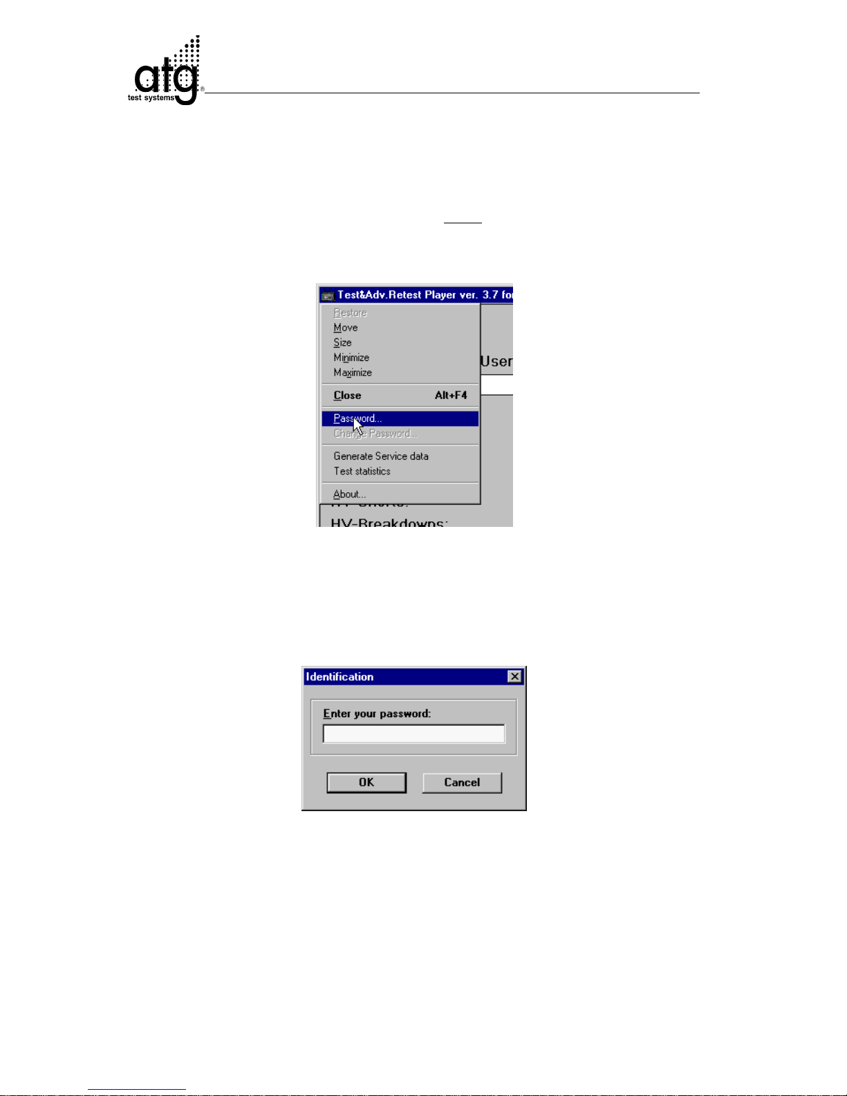
In the task window of the window Test Player once click on the control-menu-box in
the upper left in order to open the menu for switching to the supervisor mode.
Menu Item Password
The pull down menu for changing the operator mode appears. After clicking on the
menu item Password, the password input window Identification appears.
Password entry
Enter the password and confirm the entry with the OK-button. The test system now
switches to the Supervisor Mode if the appropriate password was entered. The
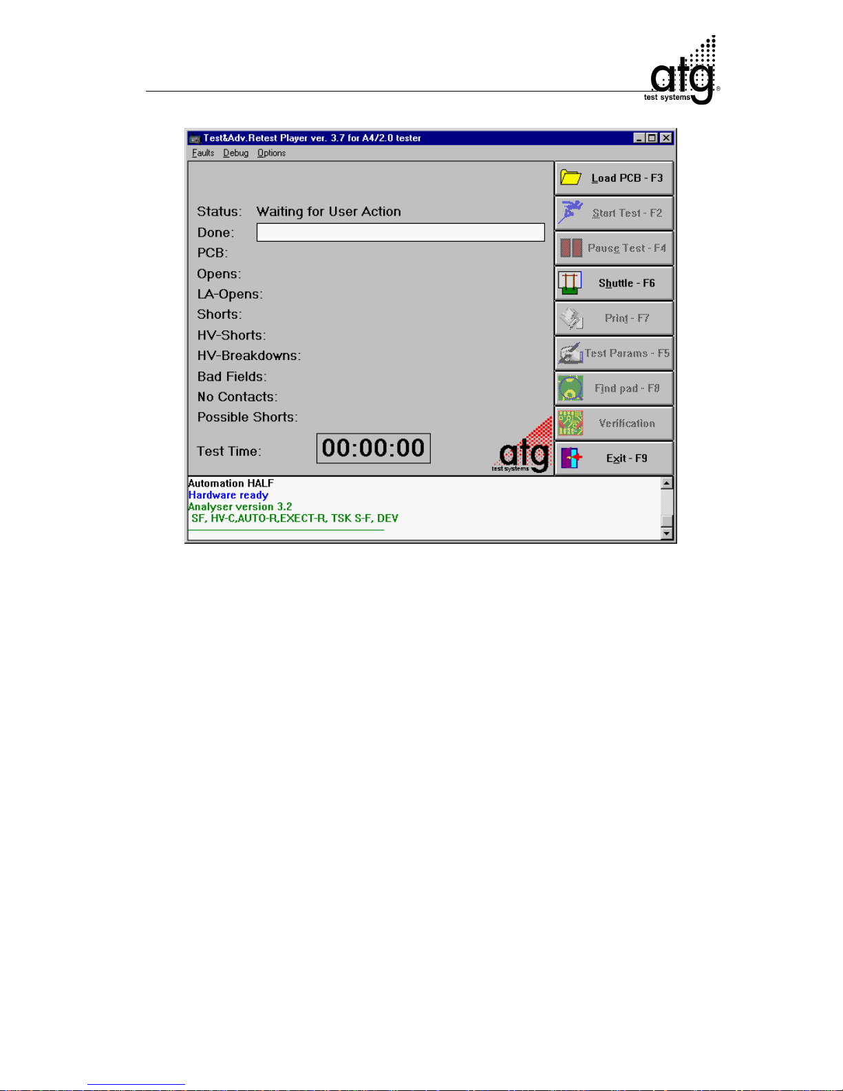
monitor display will change as shown in the following:
Page 48
C-3
Supervisor Mode A 3 V3.7
Opening screen supervisor mode
For returning to the User Mode just enter the password again in the same manner as
described before.
Page 49
C-4
Supervisor Mode A 3 V3.7
7.3 Changing the Password
After the first installation of the A 3-software package no password is set. The
supervisor functions are therefore freely accessible to anyone. The test system can be
password protected and the password can be changed at any time.
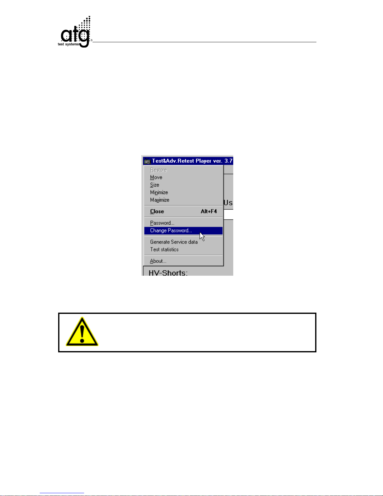
In order to enter a password, switch to the supervisor mode and open the control menu
box in the upper left of the Test Player-window. The menu item Change Password
for entering a new password or changing an existing one is located here. You can only
assign one password. Attention! Do not forget the password!
Menu Item Change Password
Attention! Do not forget the assigned password;
otherwise, it is impossible to enter the supervisor
mode!
Page 50
C-5
Supervisor Mode A 3 V3.7
7.4 Generate Service Data
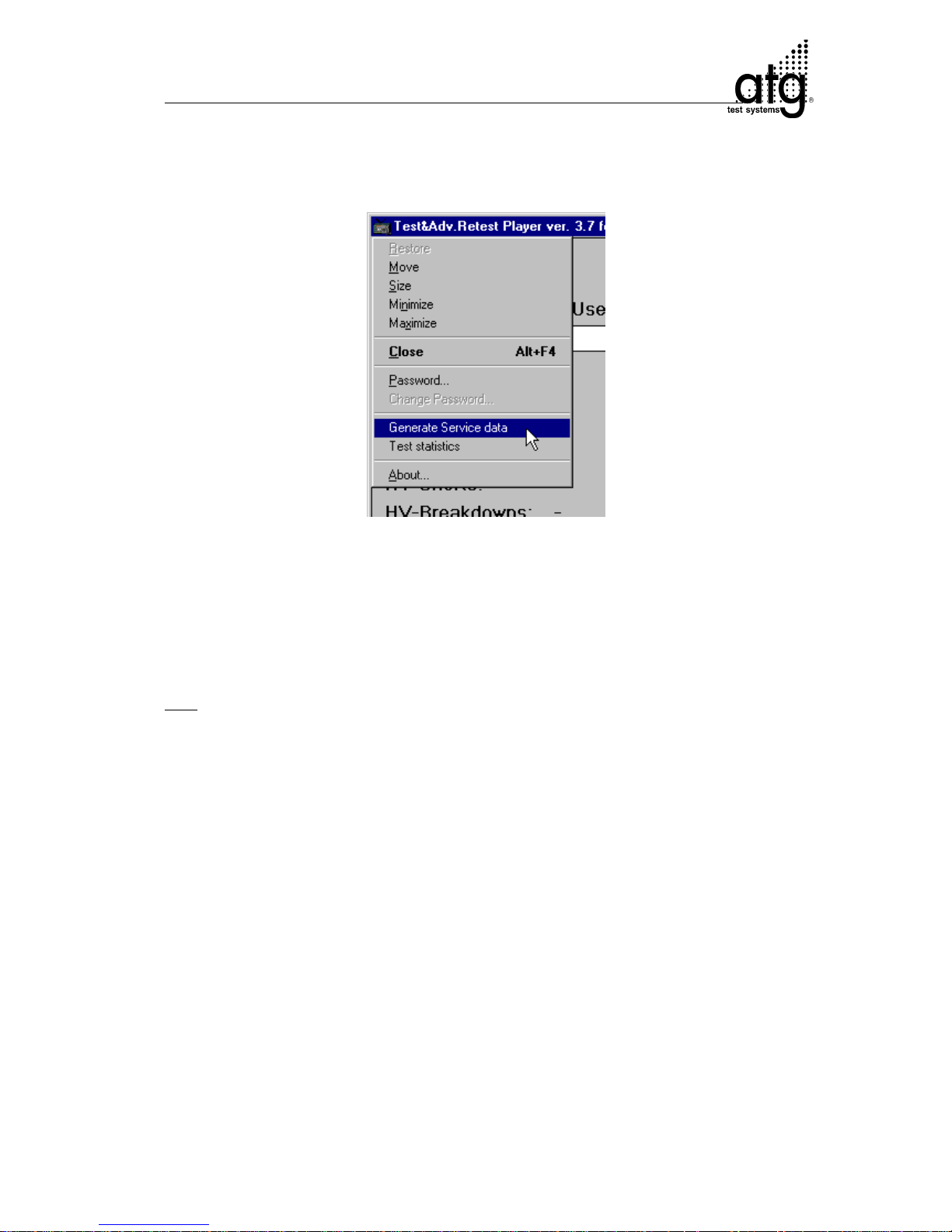
The item Generate service data creates a directory with different files, which will
enable a service department employee of "atg test systems" to recognize the
cause of a test problem. This service-file will be written to directory
C:\programms\atg\dump as a compressed ZIP-file. Send this file to the service
department of atg test systems.
E-mail adress: [email protected]
Hint:
This file is also created with every software crash. Sort the files in order of date to
find the current one.
Page 51
C-6
Supervisor Mode A 3 V3.7
7.5 Test statistics
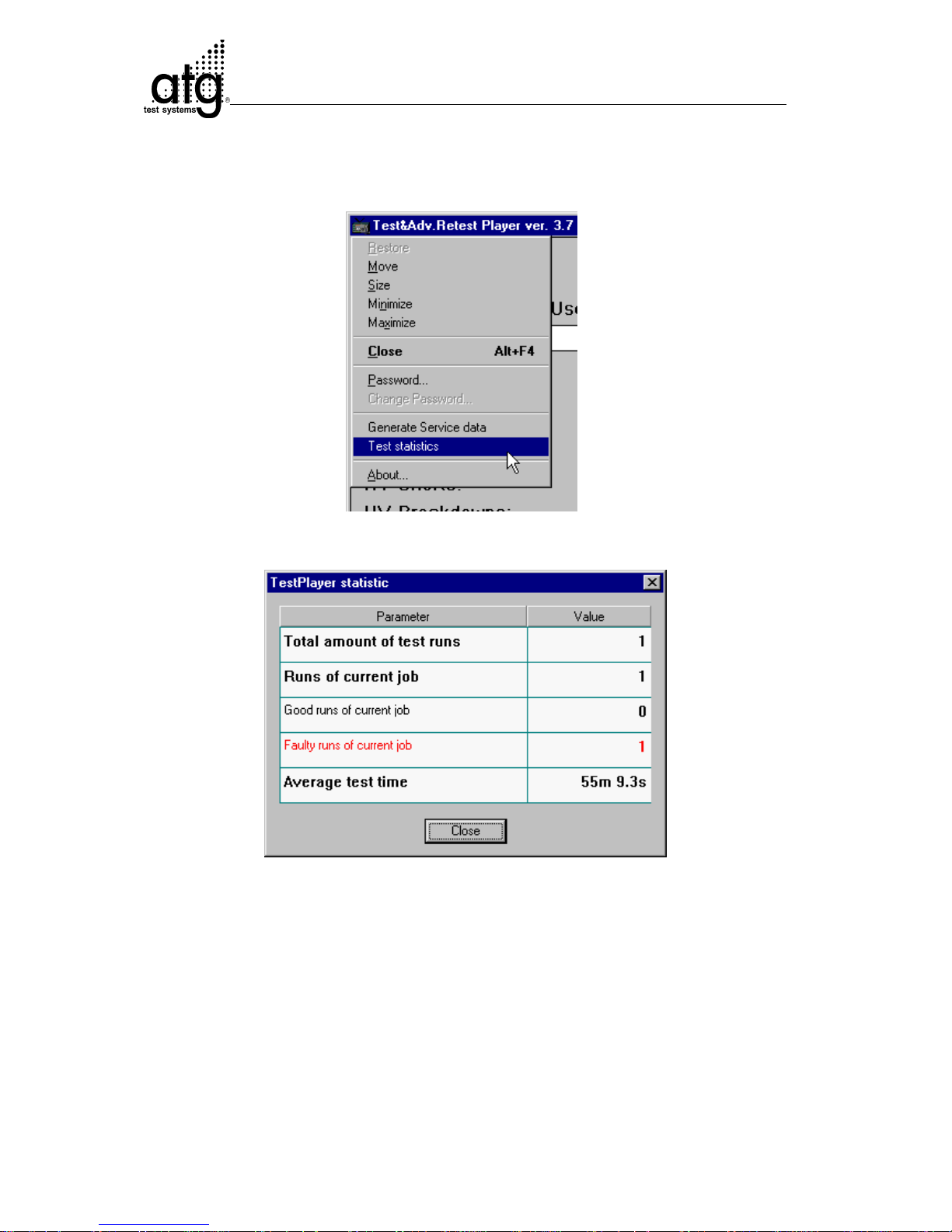
You can always open the wirndow Testplayer statistic. This window shows a
summary of the done jobs sice turning on the test system.
Total amount of test runs
Runs of current job
Good runs of current job
Faulty runs of current job
Average test time
Page 52
C-7
Supervisor Mode A 3 V3.7
7.6 The operating window of the supervisor
mode
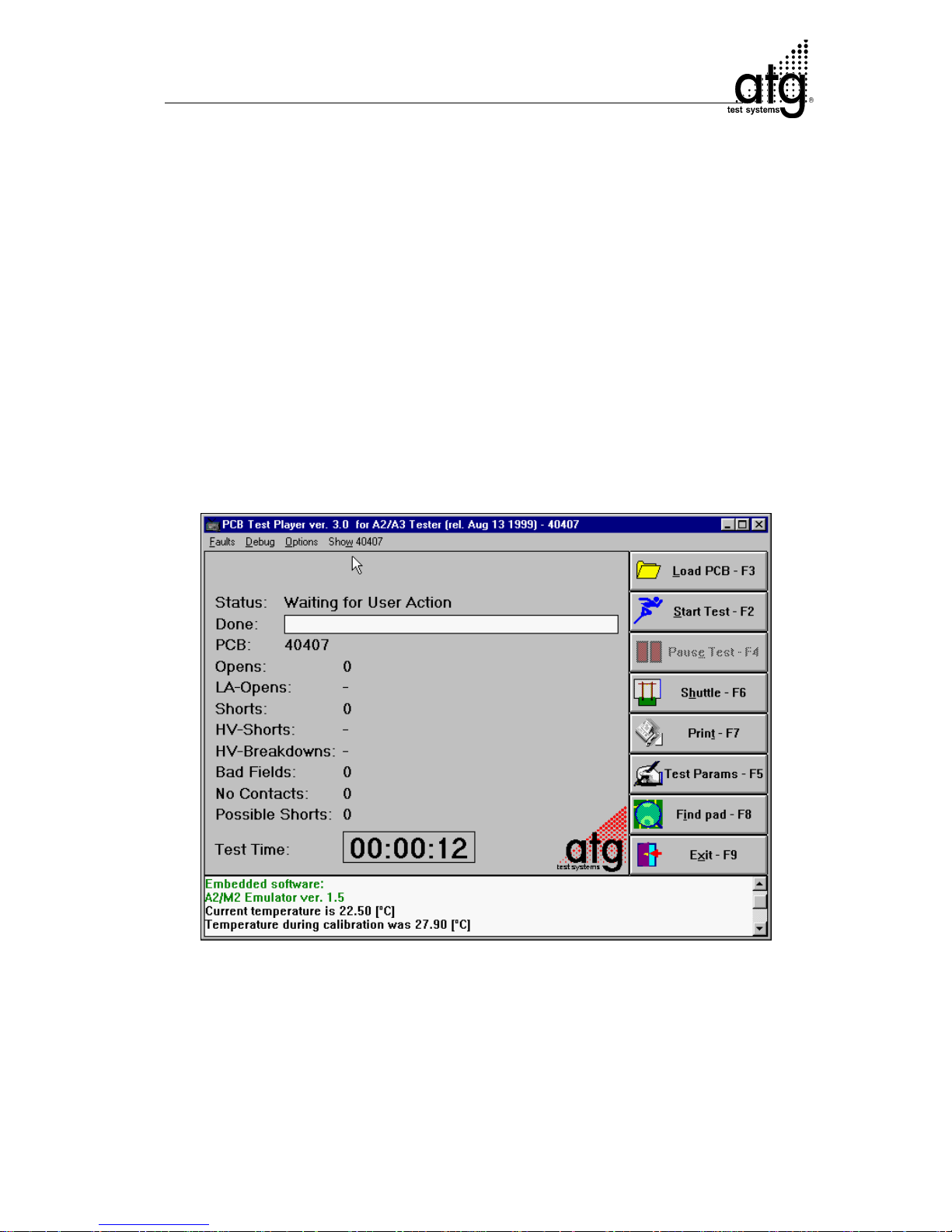
The software buttons of the user mode are also functional in the supervisor mode.
Modified or new are:
– for a job loaded, the function Show <boardname> is available in the top menu
bar of the action window, providing an extensive sub-menu.
– the F8-key is now assigned the function Find pad.
– a new button is provided: Exit F9, for closing the Test Player.
– In the supervisor mode, system messages are displayed in a status window in
the bottom section of the action window. Double-clicking this status window
maximizes it, or vice versa.
– The Test Params button (F5) provides a lot more functions.
Opening screen supervisor mode
Page 53

C-8
Supervisor Mode A 3 V3.7
7.7 The Functions of the new Supervisor
Mode Buttons
In the supervisor mode, the following new buttons are available in the right side of
the window:
Button Find Pad (F8)
With the button Find pad, you can find individual pads on the board with the
camera or contact them with a test probe. The board must have been scanned
before; otherwise, this menu item cannot be started. For the opposite case, the
board is first scanned automatically after the function Find pad is executed.
Button Exit (F9)
The Exit (F9) button closes the TestPlayer.
Page 54
C-9
Supervisor Mode A 3 V3.7
7.8 The Main Menus of the Supervisor
Mode
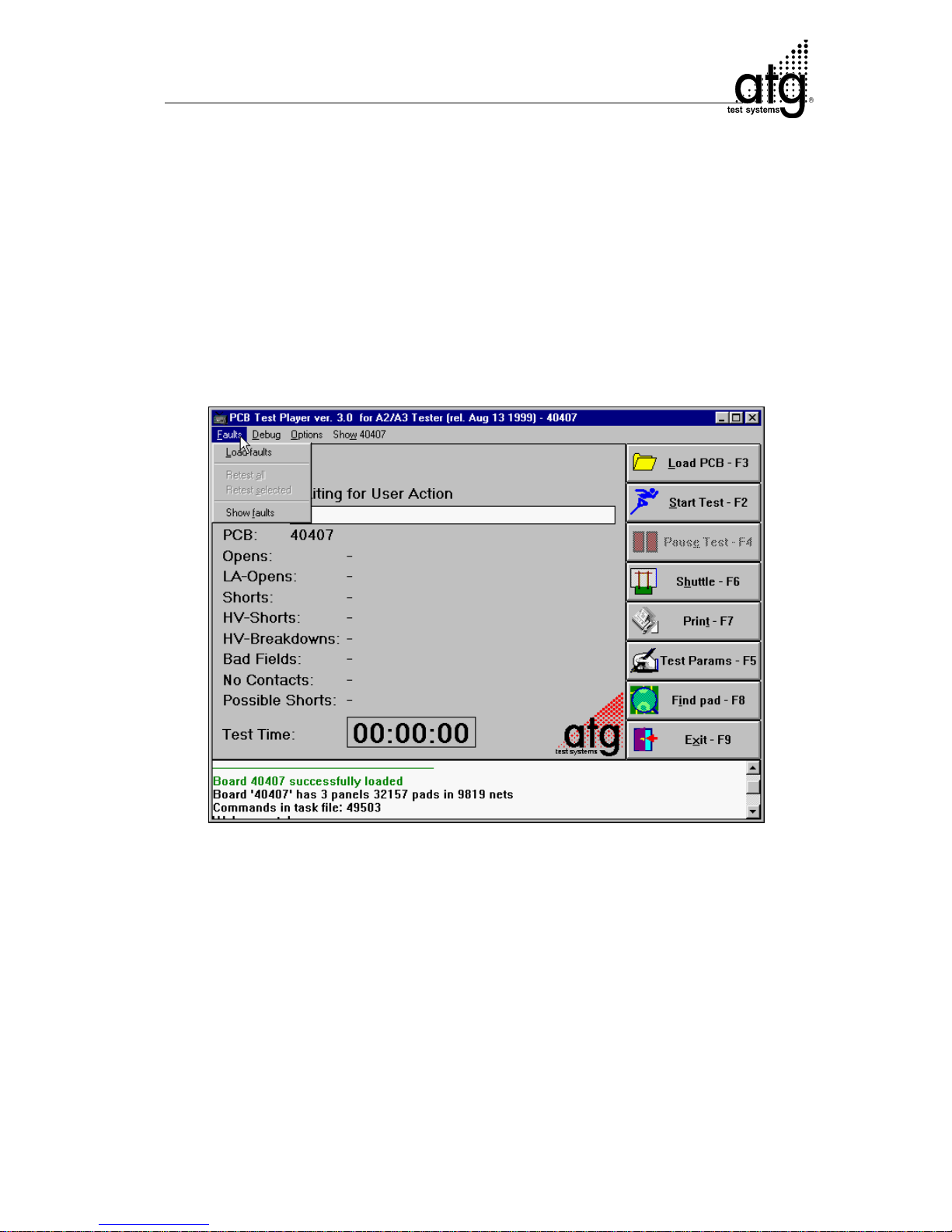
7.8.1 The Main Menu Faults
In the Faults main menu, you can retest the entire or selected parts of the faults data
of a loaded and fastened board and carry out ohmic measurements between two pads
of your choice.
Main Menu Faults
These fault categories can be retested:
- Opens
- Shorts
- Resistor-Opens
and
- Resistor-Shorts
- HV-Shorts
- Breakdowns
The following faults categories cannot be retested:
- Bad Fields
and
- No Contacts
Page 55

C-10
Supervisor Mode A 3 V3.7
The requirements for the application of this retest function are:
- The board must already be scanned.
A board is automatically scanned after starting the functions Show Faults, Retest
All or Retest Selected provided the board had not been scanned before. The
selected function only starts after the scanning is completed. The menu item
Scanning of the test parameters (F5) should be enabled.
- The data set <boardname>.les, <boardname>.vw, <boardname>.ant,
<boardname>.tsk must not have been modified in the fault file to be loaded.
A fault file being loaded is displayed in gray with the addition not valid, if the
current data set of the directory \boards\<boardname> does not correspond to data
set of the fault file at time of creation.
Hint:
An extensive verification mode is offered by atg test systems for all flying probe test
systems. With this verification extension you can retest found faults (also from grid test
systems).
7.8.2 The Menu Items of the Main Menu Faults
7.8.2.1 Load Faults
With menu item Load Faults you can select fault files of earlier tests for retesting.
The fault files <boardname>.flt are listed in lot-directories. These directories are
located in your lot-directory and are named 001, 002... each number representing a lot.
Hint:
Lot = a working cycle of the test system, starts with the loading a new job. The lot
contains all following test results of this board type. The lot is closed when exiting the
Test Player or when loading a new board. The Test Player automatically creates a
new directory if a lot is tested at a later point.
Run = a single test within a lot. The therefore created run-no. is assigned as ID-no. to
the tested board.
Hint:
For the retest of multi-sample jobs it is necessary to fasten the panels in the exact same
position in the shuttle as in the first test.
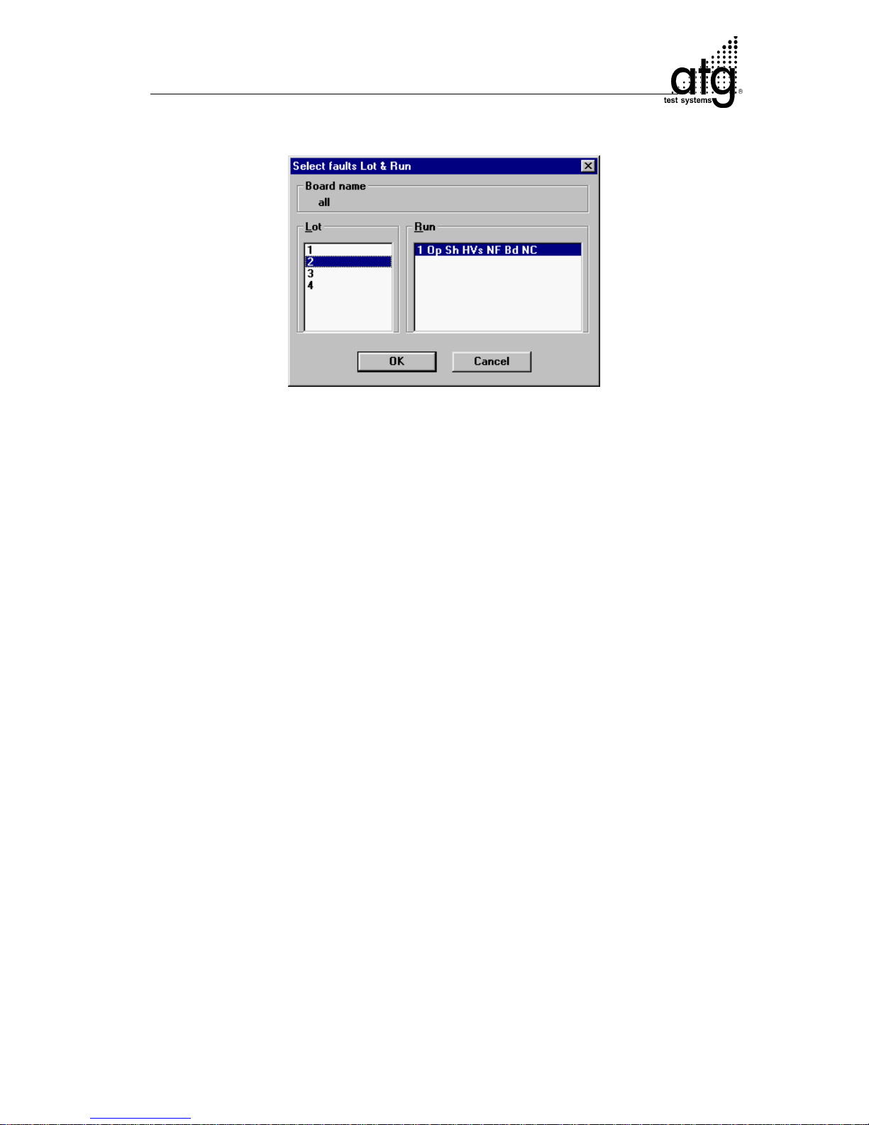
After selecting the menu item Load Faults a divided selection window is displayed.
Select the desired lot and run for retest. This run is now available for the following menu
items Retest All, Retest Selected and Show Faults.
Page 56
C-11
Supervisor Mode A 3 V3.7
Lot- and Run Selection
Following the run number, the faults it includes are shown in abbreviations. For the
case that the selected run contains no fault data the program will display: No Faults
in selected lot or run
7.8.2.2 Retest all
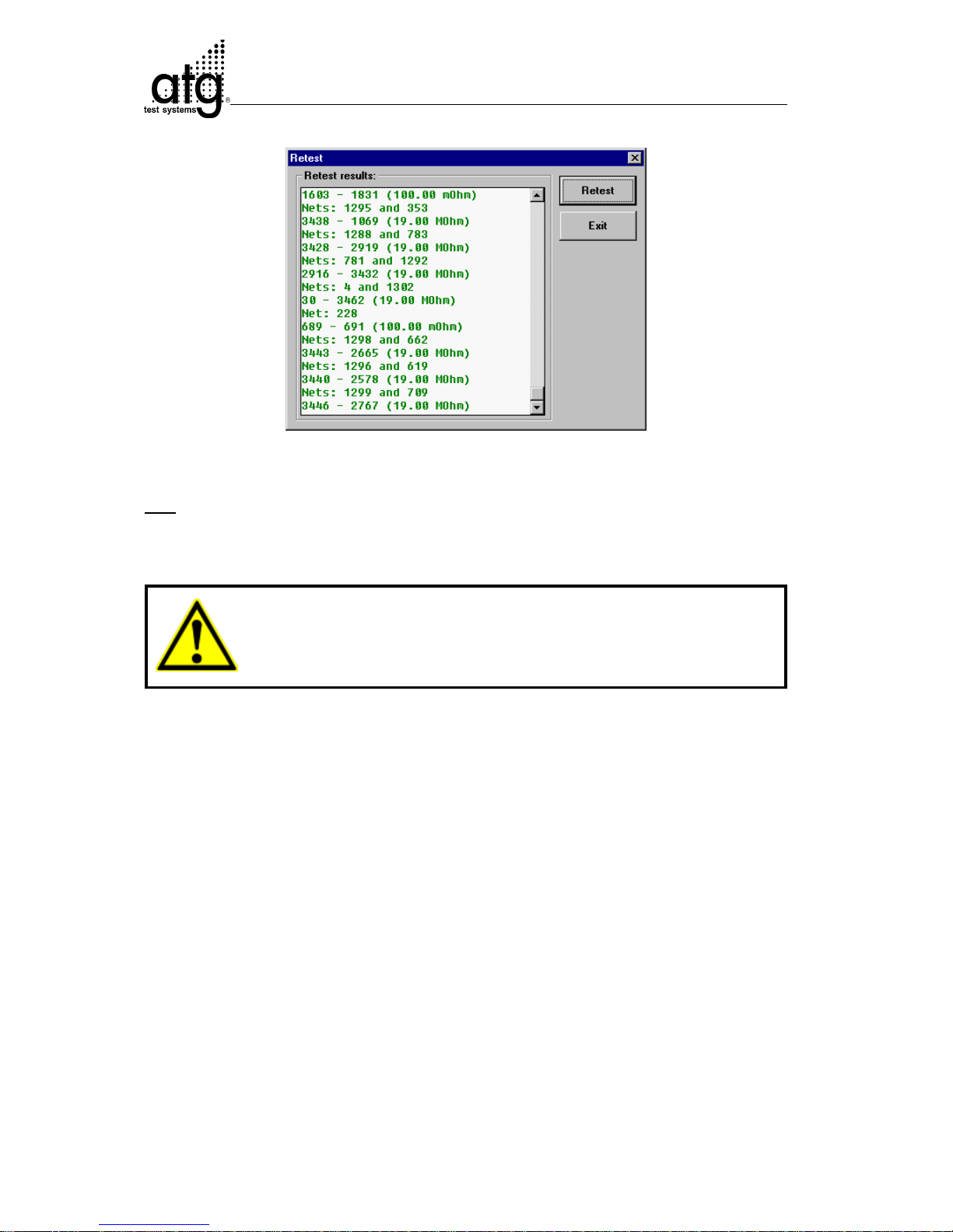
The menu item Retest all can only be activated after you have loaded a fault file with
at least one fault with the menu item Load Faults. All testable faults of the loaded fault
file are retested and listed, if the Retest-button in the Retest-window is pressed.
If more faults than can be listed in the window are confirmed, you can view them by
using the scrollbar on the right side of the window. The retested faults are displayed
in green if they do not confirm as faults. Faults displayed in red were reconfirmed as
faults in the retest.
Page 57
C-12
Supervisor Mode A 3 V3.7
Retest all
Hint:
In the menu item Retest all you cannot refresh your fault file. Furthermore, it is
impossible to printout the contents of this window.
7.8.2.3 Retest Selected
The menu item Retest selected enables the retest of any desired parts of your fault
file. As mentioned for the menu item Retest all, the menu item Retest Selected can
only be activated after a fault file was loaded with Load Faults.
The handling is identical to the menu item Retest All.
You can apply the menu item
Retest all
for the inspection
of repaired boards. However , this additional inspection
cannot replace an entire retest of the board!
Page 58
C-13
Supervisor Mode A 3 V3.7
Retest Selected
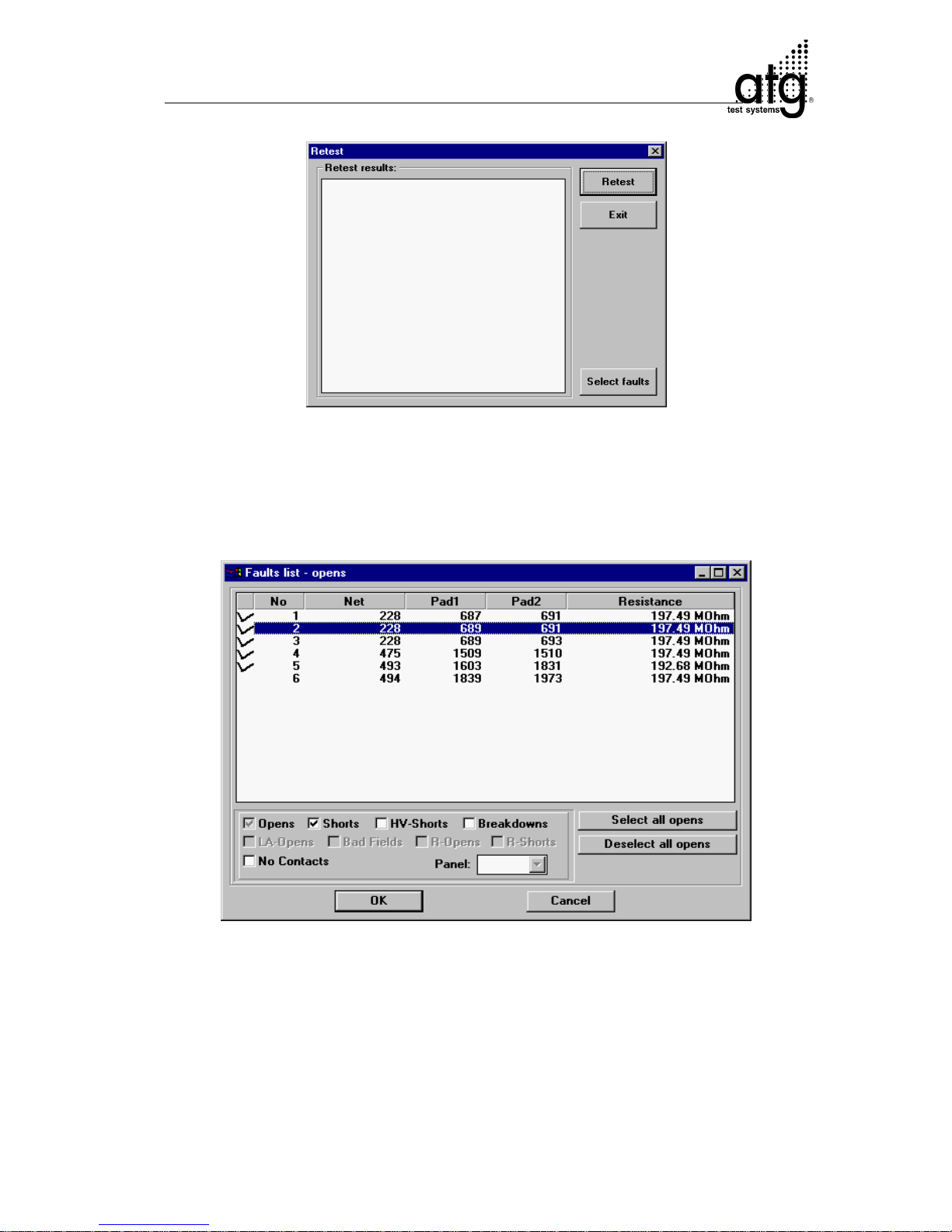
The menu item Retest Selected additionally contains the button Select faults, which
opens the selection window Faults list in which you can make a selection of the faults
to be retested.
Fault Selection List
The bottom of the Faults list-window all possible fault types of the loaded run are
listed. A fault type is displayed in gray if it is not included in the fault file. The selection
box Panel lets you choose which panel you would like to retest or if you would like to
retest all panels.
Page 59

C-14
Supervisor Mode A 3 V3.7
In the top of the selection window the individual faults of the activated fault type are
displayed. Faults marked for retest are checked off. For (de) activating a fault, remove
or add its marker with a mouse click or by pressing the space bar.
With the buttons Select all <Fault type> or Deselect all <Fault type > you can activate
or deactivate all faults of the list.
In order to start the retest, confirm your selection with the OK-button. The Faults listwindow is closed and the Retest-window is active again. Start testing with the Retestbutton. All verified faults are shown in the scroll-list during the retest. The retested
faults are displayed in green if they do not confirm as faults. Faults displayed in red
were reconfirmed as faults in the retest.
As mentioned for the menu item Retest all there is no possibility of printing out the
contents of the scroll-list or of actualizing the fault file.
7.8.2.4 Show Faults
The menu item Show Faults serves the purpose of specifically inspecting individual
faults. This menu item supports only sequential single measurements. The pads for
measurement can be selected from the loaded fault file (see Load Faults) or directly
entered.
During this the ohmic resistance between the test pads is measured. The contacting
of the pads is carried out in a ”stand bye”-mode, i.e. the test heads are slowly directed
to the pads, contact them for approximately 5 seconds and then remain above the
contacted pads. This enables a closer analysis of the individual measurements in
regards of the contacted pads.
Page 60
C-15
Supervisor Mode A 3 V3.7
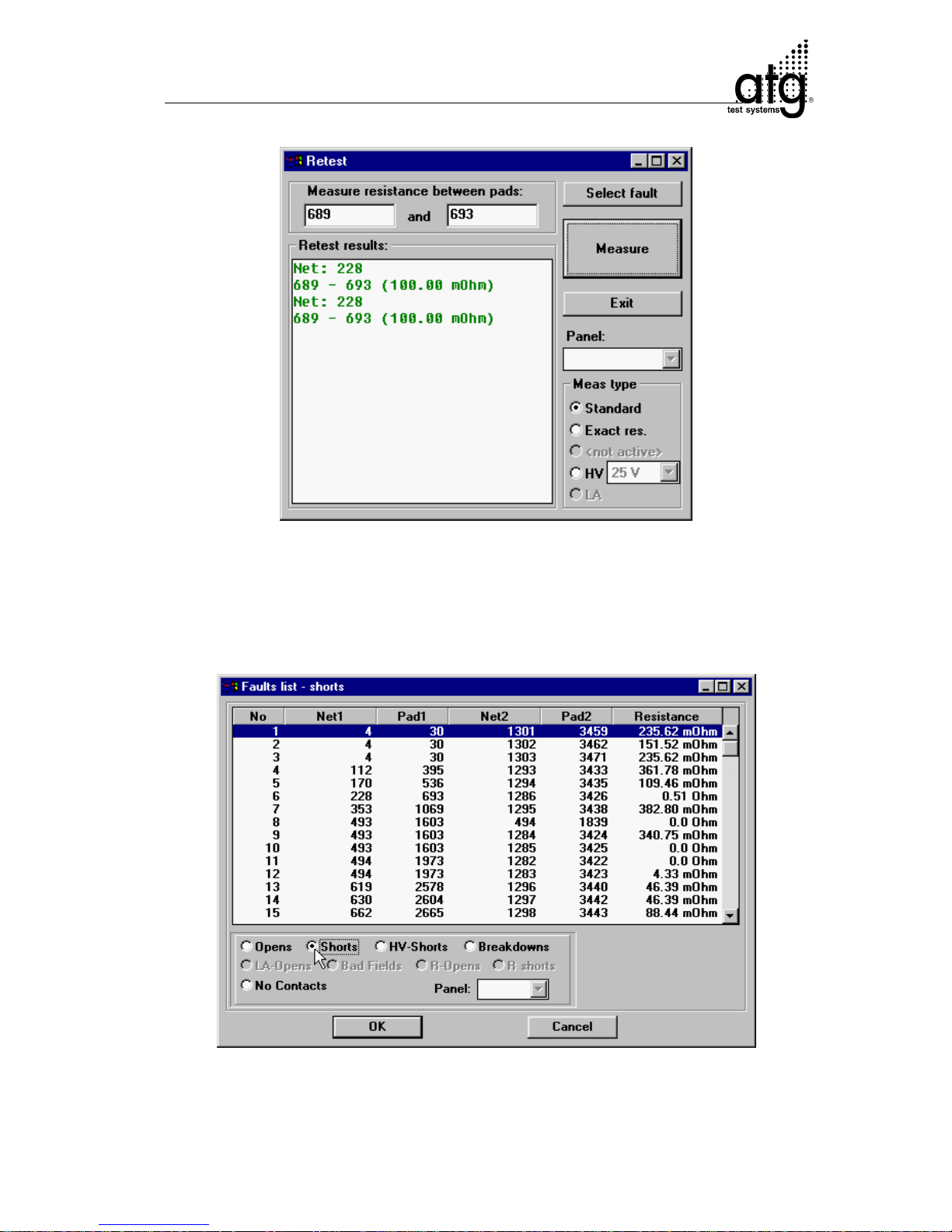
Select Pads for Retest
With the Select fault-button you can select the pads of an individual fault from the
loaded faults list. The Faults list-window is opened from which a fault can be selected.
Select Faults for Retest
Page 61

C-16
Supervisor Mode A 3 V3.7
The functions of the Fault list window are described in the menu item Retest
Selected (p. C-10).
Start the individual test with a double-click on the desired fault of the faults list. During
this the faulty pads are transferred to the Retest-window and the test results are
displayed. For a confirmed fault the measuring value is displayed in red and vice versa
in green.
Hint:
Upon opening the Fault list-window entirely covers the display of the retest outputwindow. In order to prevent this from happening move the Retest-window for example
upward ahead of opening the Fault list-window.
In order to carry out a measurement between to random pads enter the both pad ID’s
in the input window underneath Measure resistance between pads. In the selection
window Panel you can select an individual panel.
The Meas type options enable the following settings for the measurement:
- Standard: Measurement at normal accuracy
- Exact res.: Measurement at increased accuracy. This measurement takes longer
since an average value of several longer lasting measurements is determined.
- HV: Set the voltage for the measurement
- LA: Enables a LA-measurement if the required hardware exists.
Page 62
C-17
Supervisor Mode A 3 V3.7
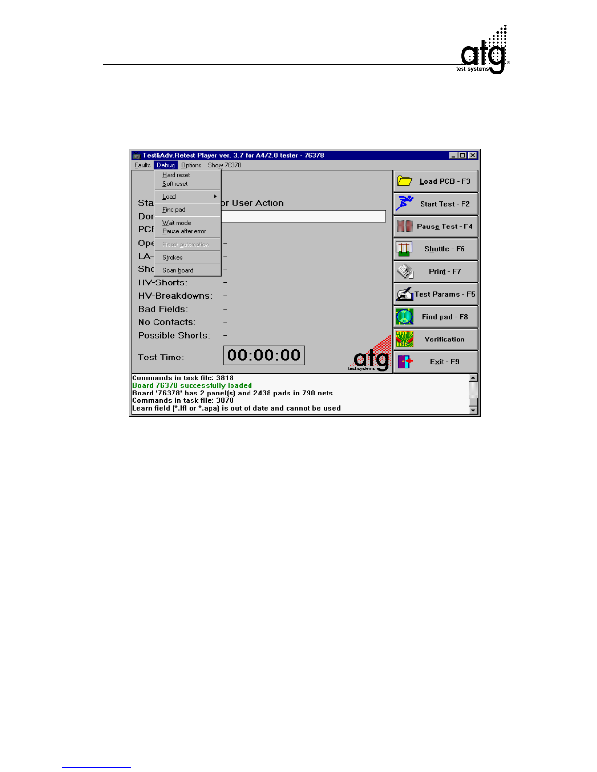
7.8.3 Main Menu Debug
Main Menu Debug
7.8.3.1 Hard Reset
The menu item Hard Reset sets back all controller cards. During this, the power
supply of the test system is not interrupted; however, all internal program activities are
deactivated.
This function is comparable to the application of an emergency off switch. In order to
put the test system back into operation you must reload all control programs (menu
item Load the entire main menu Debug / Load), or exit the Test Player and restart.
7.8.3.2 Soft Reset
With the menu item Soft Reset you can set the entire test system back to the ”zero
position”. The test probes and the cameras are directed to their start position which
they approach after the system is loaded. All incomplete command sequences are
terminated and a short system check is carried out.
Page 63

C-18
Supervisor Mode A 3 V3.7
This command does not have a negative effect on the test system; it only produces a
defined condition. Only execute a Soft Reset when the test system is inactive.
7.8.3.3 Load
With the sub-menus of the menu item Load you can reload necessary system
programs and data required for the initialization of the test system, either individually
or entirely (e.g. after a Hard-Reset).
All
Loads and starts the entire system programs in the following order:
1. Crate-program (control program) of the test system.
This program is saved as c_prog.bin in the \hardware-directory.
2. Tester-layout (a hardware specific initialization file).
This file is saved as f_layout.bin in the \hardware-directory.
3. Probe-program (control program for the test probes).
This program is saved as f_prog.bin in the \hardware-directory
4. Correction-tables (for aligning the probes and camera on the test system matrix).
These tables are arranged corresponding to the numbering of the individual probes
(e.g. rail0l.cor for probe 0, left). The individual programs are saved as rail??.cor in the
\hardware-directory
The function Load all is nearly identical to the automatic loading procedure when
starting the Test Player. Only the loading of the image capture software for the
cameras is not implemented here.
Load & Run Crate
Loads and starts the Crate-control program (c_prog.bin).
Load Layout
Loads the test system-layout (f_layout.bin).
Load & Run Fingers
Loads and starts the probe-program for the individual probe controllers (f_prog.bin).
Load Correction Tables
Loads the correction tables (rail??.cor).
Page 64
C-19
Supervisor Mode A 3 V3.7
7.8.3.4 Find Pad
With the menu item Find Pad you can find individual pads on the board with the
camera or contact them with a test probe. The board must have been scanned before;
otherwise this menu item cannot be started. Is the opposite the case, the board is first
scanned automatically after the function Find Pad was executed.
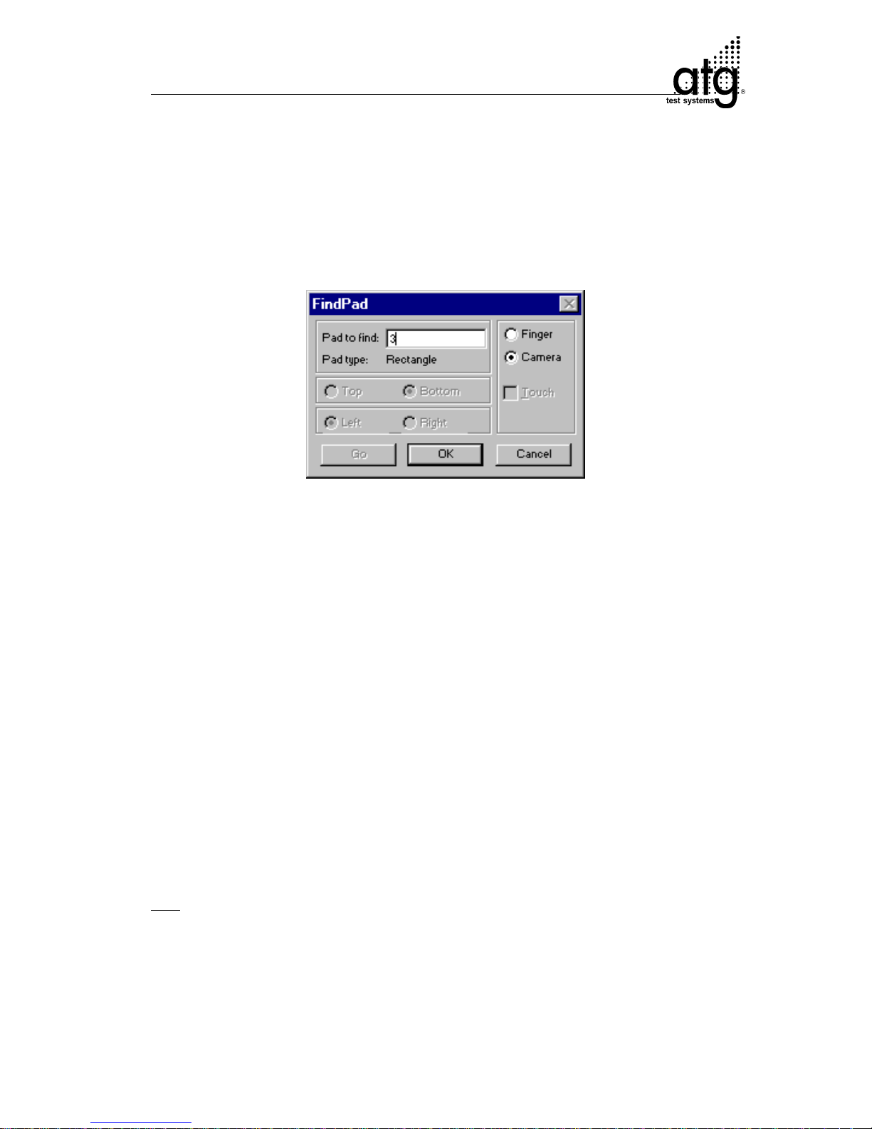
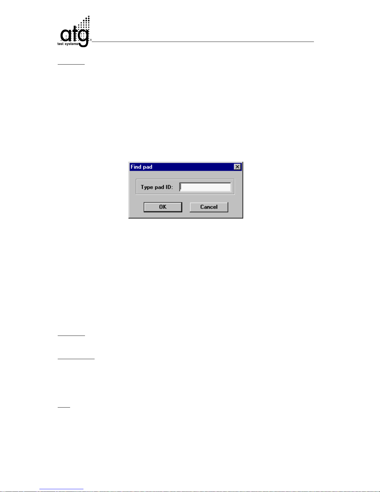
Find Pad
In the input box Pad to find of the Find Pad-window enter the pad-ID of the pad you
wish to inspect. If the searched pad is not located on panel 1, the panel can be entered
separated by a slash. Choose which device you would like to apply for finding the pad,
either Camera or Finger, and click the OK-button.
A short information on the pad is displayed underneath Pad type. Press the Go-button
to find the pad.
In the boxes Top/Bottom and Left/Right you can exactly specify the pad. If the camera
was activated, the selected pad will be displayed in red in the screen’s center. The
Find Pad-window will be available again after clicking the left mouse-button. The right
mouse-button closes the Find Pad-window.
If you activated Finger, one test head will move to the desired pad and remain there
without making contact. Enable Touch for contacting the pad.
You can switch between Finger and Camera. In case of camera and test probe
interference the software will direct either the test head or the camera back to its
original position.
Close the action-window with the Cancel. This automatically executes a Soft-Reset
of the test system.
Hint:
You cannot activate Find Pad if the optical scanning is disabled in the Test Params
(F5)-menu.
Page 65

C-20
Supervisor Mode A 3 V3.7
7.8.3.5 Wait Mode
With the menu item Wait Mode you can run the test procedure step by step.
Movements and measurements of the task file are executed sequentially. During this,
the test speed is reduced and the analysis of the detected faults is therefore facilitated.
Due to the reduced test speed it is now possible to online display information about the
test procedure in the status window.
For that purpose an example line:
Resistance 2 <-> 3 [5 <-> 385 / 3]
Explanation:
A resistance measurement was carried out with the probes 2 and 3 between the padID’s 5 and 385 of panel 3.
The Wait-mode is selected, if it is checked-off in the pull-down-menu.
Hint:
During testing, the Wait-mode can be turned off/on. Afterwards, testing is executed in
normal speed.
7.8.3.6 Pause after error
With the menu item Pause after error you can, similar to Pause Test (F4), interrupt
a test run. A Pause after error is only then carried out after a fault was detected (short,
open). The button Pause Test (F4) changes to Resume Test (F4). The message
Test
Paused
is displayed. With the Resume Test (F4)-button you can continue testing.
However, in normal test speed this function becomes useless since the test system
first processes the command buffer (up to 200 commands), before the Pausecommand comes into effect.
In the Wait-mode (main menu Debug / menu item Wait mode), however, you can
pause the test every time a fault is detected. Only apply the combination of Wait mode
and Pause after error for debugging.
Pause after Error is selected, if it is checked off in the pull-down-menu.
7.8.3.7 Reset automation
The test system A 3 is also available as fully automatic system A 3-a. This feature does
not work with A 3.
Page 66
C-21
Supervisor Mode A 3 V3.7
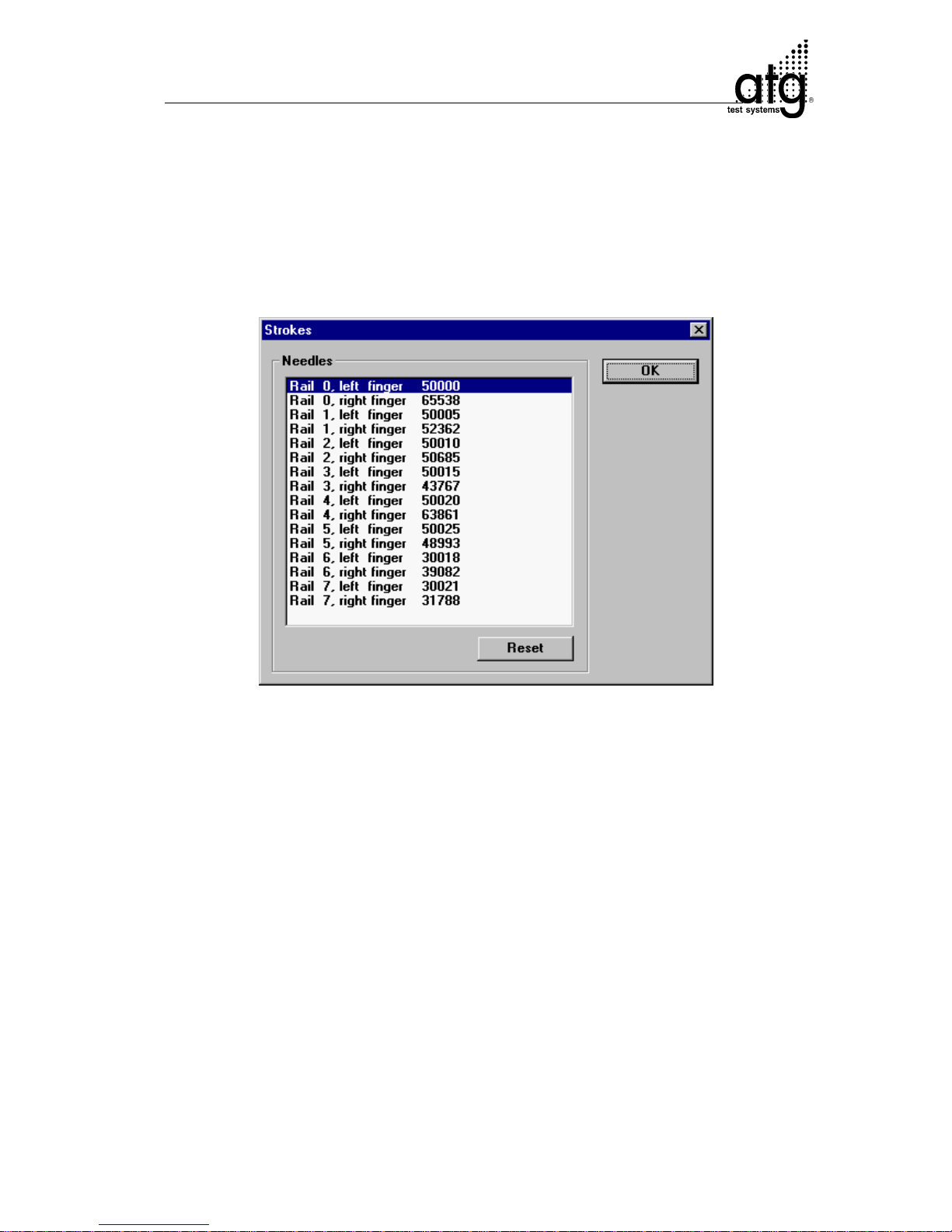
7.8.3.9 Strokes
The menu item Strokes tells you how often test probes have made contact during their
operating life. This way you can keep track of their operating life. The statistics file
strokes.cnt of the \hardware-directory is listed for this purpose. This file is actualized
with each Soft-Reset.
Test Probe Contacts
After a test probe tip exchange you should reset this counter function. In order to do so,
click on the line of the exchanged probe and press the Reset-button.
7.8.3.10 Scan Board
With menu item Scan Board you can start the scanning and this way determine the
exact board position.
The scan result is displayed in the following format.
Example:
X = 0,999457x – 0,000014y – 44
Y = 0,000014x + 9,999457y + 1950
Of these lines only the X- and Y-offset of the board are of interest:
The X-offset is - 44 µm and the Y-offset + 1950 µm.
Page 67

C-22
Supervisor Mode A 3 V3.7
The remaining coefficients represent internal calculations results and are of no
interest to the user.
Hint:
It is impossible to activate the menu item Scan Board, if scanning was disabled in the
Test Params (F5).
The Advanced-button opens the Advanced Video Setup-window.
Attention! The settings in this window must not under any circumstances be changed.
Page 68
C-23
Supervisor Mode A 3 V3.7
7.8.4 Main Menu Options
Main Menu Options
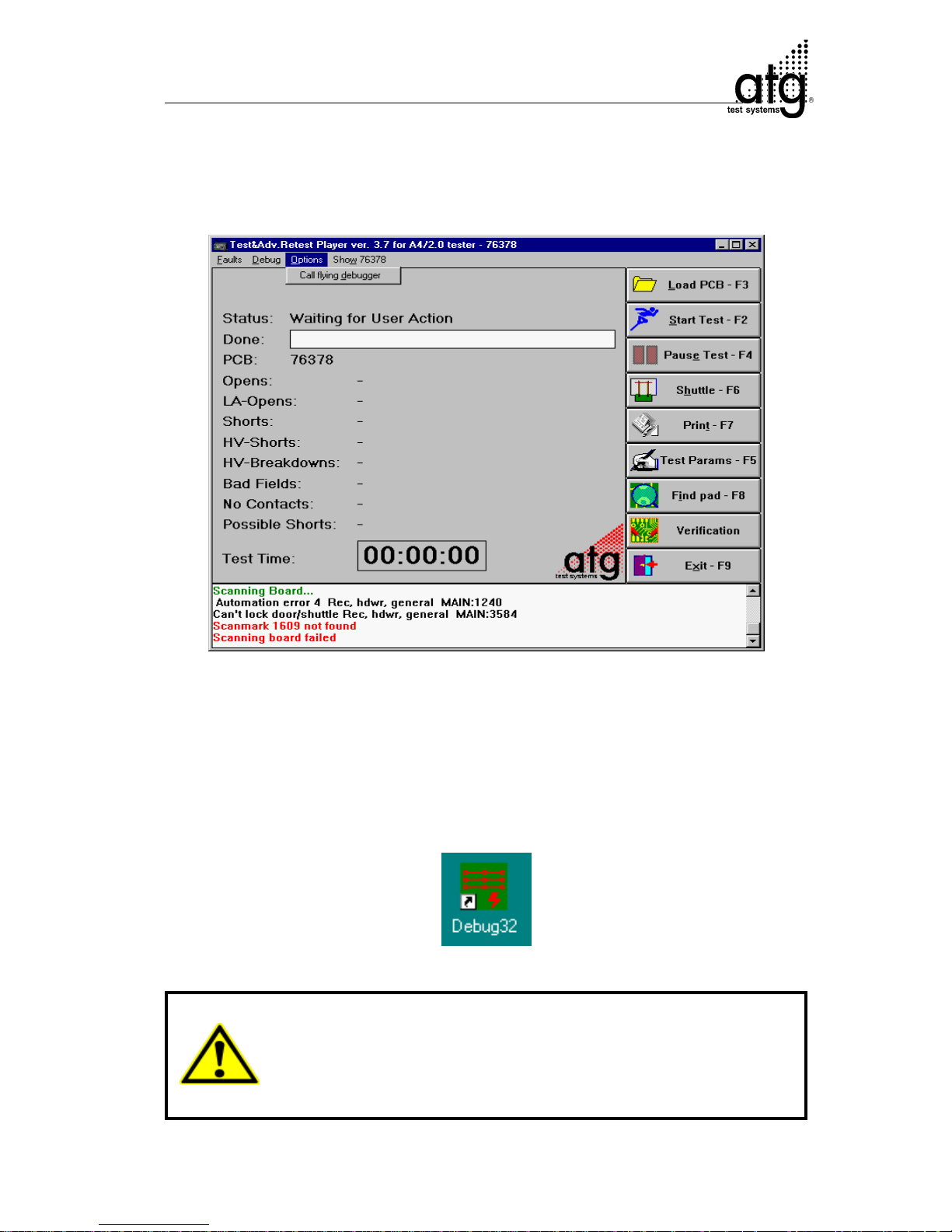
7.8.4.1 Call flying debugger
Do not use the menu item Call flying debugger for executing a C-Adjust or for
calibrating the test system. Use the separate program icon Debug32 on the Windows NT desktop. This menu item is only used for the atg service support.
Start Debugger
Attention! Only use the program module flying debugger if you are familiar with it!
Improper use may considerably alter the settings of
the test system and may cause hardware damages!
Page 69
C-24
Supervisor Mode A 3 V3.7
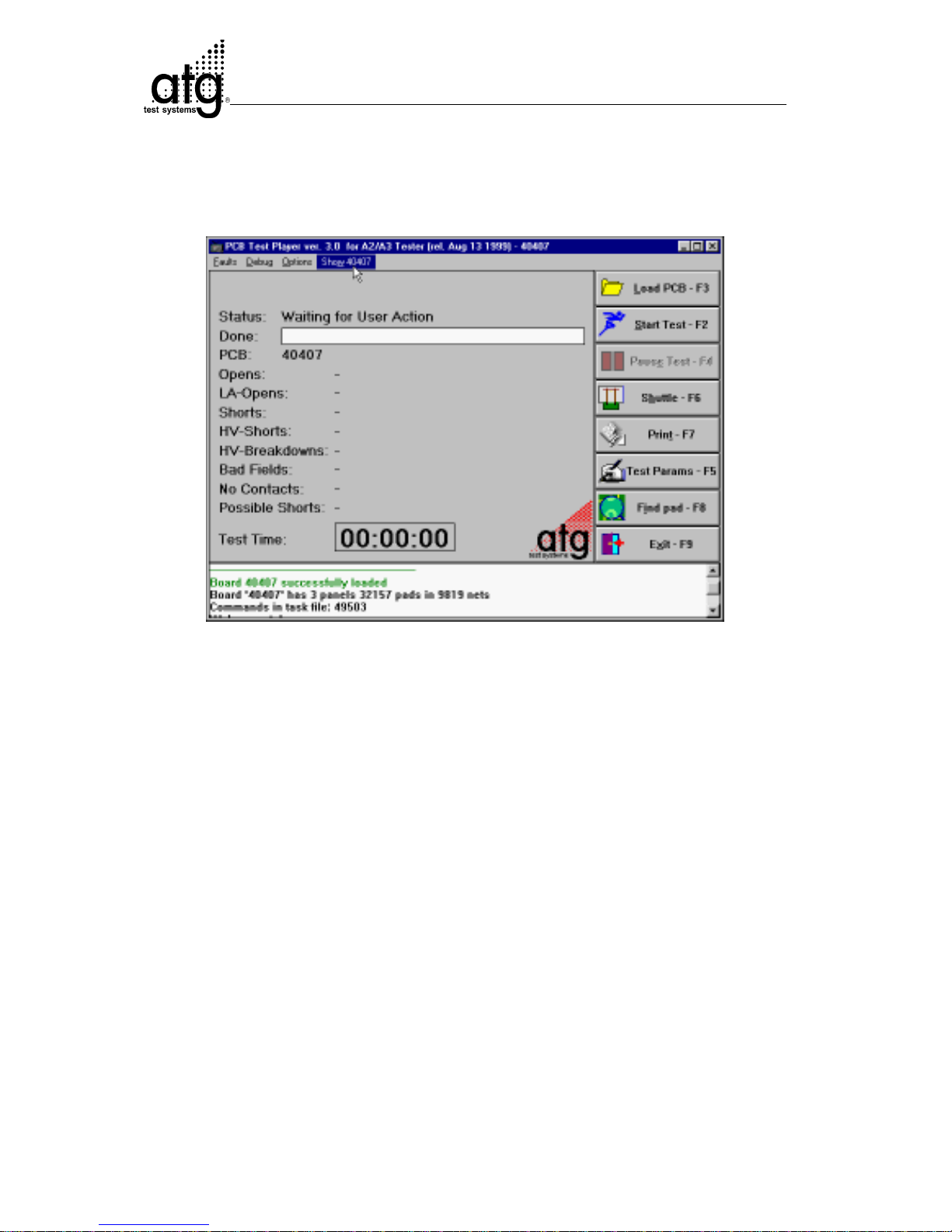
7.8.5 Main Menu Item Show <boardname>
Starting the sub-program Show <boardname>
After having loaded a job, the main menu item Show <boardname> is available, via
which you enter an extensive, graphically oriented sub-program. In this sub-program
you can read back all relevant information on the tested board.
The sub-program Show <boardname> is not available during a test run.
Page 70
C-25
Supervisor Mode A 3 V3.7
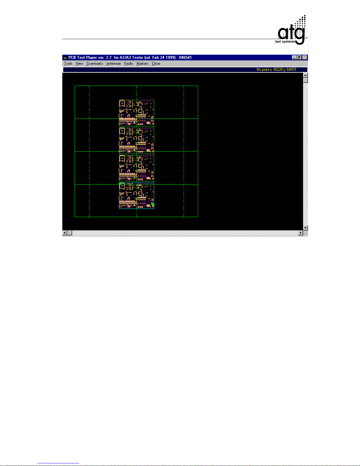
Sub-program Show <boardname>
The main menu item Show <boardname> displays the board in a green line graphics
representing the operating areas of the individual rails. Additionally, three vertical
striped lines are shown. The outer lines represent the margins of the camera operating
range in X-direction while the middle line shows the test field center and serves as
orientation.
The sub-program Show <boardname> does not provide the edit functions known
from the DPS.
In the information bar above the graphic window information about the current position
and the cursor status is displayed in yellow. Here, the pad ID with pad coordinates is
shown if the cursor is directly positioned on a test pad. The text No Point, followed by
the cursor coordinates is shown if the cursor is not located on a test pad.
In the left of the info bar additional information is displayed in blue provided that the
corresponding functions of the menus were selected.
Positions are stated in 1/100 mm units and correspond to the coordinates of the test
field (shuttle coordinates).
For more comfort, the most important action and query commands are available in a
pop up menu via a right mouse-button click.
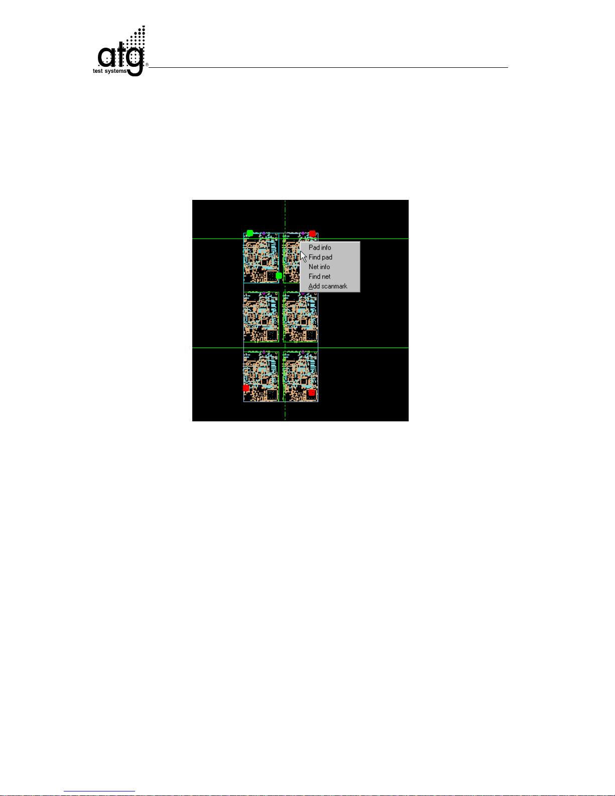
The following functions are available if the cursor is located on a test pad (recognizable
in the info bar) when the right mouse-button is pressed:
Page 71
C-26
Supervisor Mode A 3 V3.7
- Pad info
- Find pad
- Net info
- Find Net
- Add Scanmark
(only available if not all scanmarks are placed
)
- Delete Scanmark
(only available if a scanmark is placed on the test pad)
Pop up menu: Commands for pads and nets
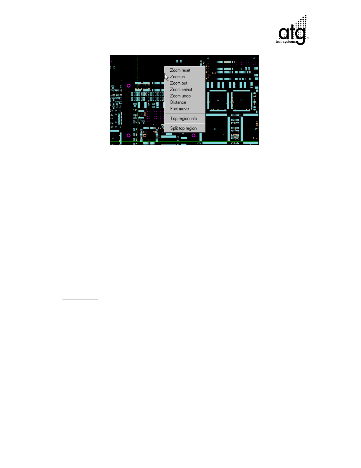
The following functions are available if the cursor is not located on a test pad
(recognizable in the info bar) when the right mouse-button is pressed:
- Zoom reset
- Zoom in
- Zoom out
- Zoom select
- Zoom undo
- Distance
- Fast Move
The following functions are available vi the cursor is not located on a test pad but
located on sample 1:
–
Divide top region
–
Divide bottom region
and if the cursor is located on a region divide line:
–
Connect top/bottom regions
Page 72
C-27
Supervisor Mode A 3 V3.7
Pop up menu for graphic commands
7.8.5.1 The Functions of the pop up menu on a Test Pad
Pad Info
With this function you can call up information on a test pad. When this function is active
the cursor has the shape of an arrow with a question mark. Place the arrow’s tip on a
test pad (whether or not you are located on a test pad is indicated in the info bar) and
click the left mouse-button. The selected pad is marked with a big reticule. The pad info
is displayed in the left of the info bar.
Example:
Pad 1488 (x=4416,y=4678 <-> x=35175,y=17293), net 3040: side:comp, tool 27,
panel 6
Explanation:
Pad-ID 1488
Pad Coordinates in the ATF-net list x 14416, y 4678
Coordinates of the test pad in correspondence to the zero-position of the test area x
35175, y 17293
Pad is located on net 3040
Pad is located on component side
(comp = component side; sold = solder side; both = double-sided)
Pad is defined as number 27 in the ATF-header
Pad is located on panel 6
For a pad not located on panel 1, the stated pad-ID is not present in the ATF-file. This
is caused by the application of the function Step&Repeat for multi-panels with which
the pad information of panel 1 is multiplied.
Page 73
C-28
Supervisor Mode A 3 V3.7
Example for Pad-IDs on multi-panels:
A net list consists of 10 nets (net number 1-10) and 50 pads. With one Step&Repeatline you have created a double-panel.
Consequently, in the first panel you will only receive pad-IDs between 1 and 50 and
net numbers between 1 and 10.
In the second panel the pad-Ids are numbered consecutively so that pad-IDs between
51 and 100 result. Pad-ID 51 is therefore the first pad of the net list of the second panel.
The XY-coordinates and tool sizes of pad-ID 51 and pad-ID 1 differ by the step width
of the Step&Repeat-shift.
Find Pad
Input Window Find Pad
For finding a pad on the board enter the wanted pad-ID in the displayed input window.
A big reticule indicates the found pad. The pad information is displayed in the info bar.
Net Info
For calling up net information about a certain pad. After activating this function, the
cursor adopts the shape of an arrow with a question mark. The net is illustrated
symbolically, if the pad is located in a net with more than one pad. The net information
is displayed in the info bar in the following format.
Example:
Net 2142 (pads 12, first pad 1229): panel 1
Explanation:
The pad is located in net 2142.
Net consists of 12 test pads.
The first pad in the net has the pad-ID 1229.
The net is located on panel 1.
Hint:
Pads are connected with lines for nets consisting of several pads. However, these
lines do not represent the real net course, they only serve as an orientation.
Page 74
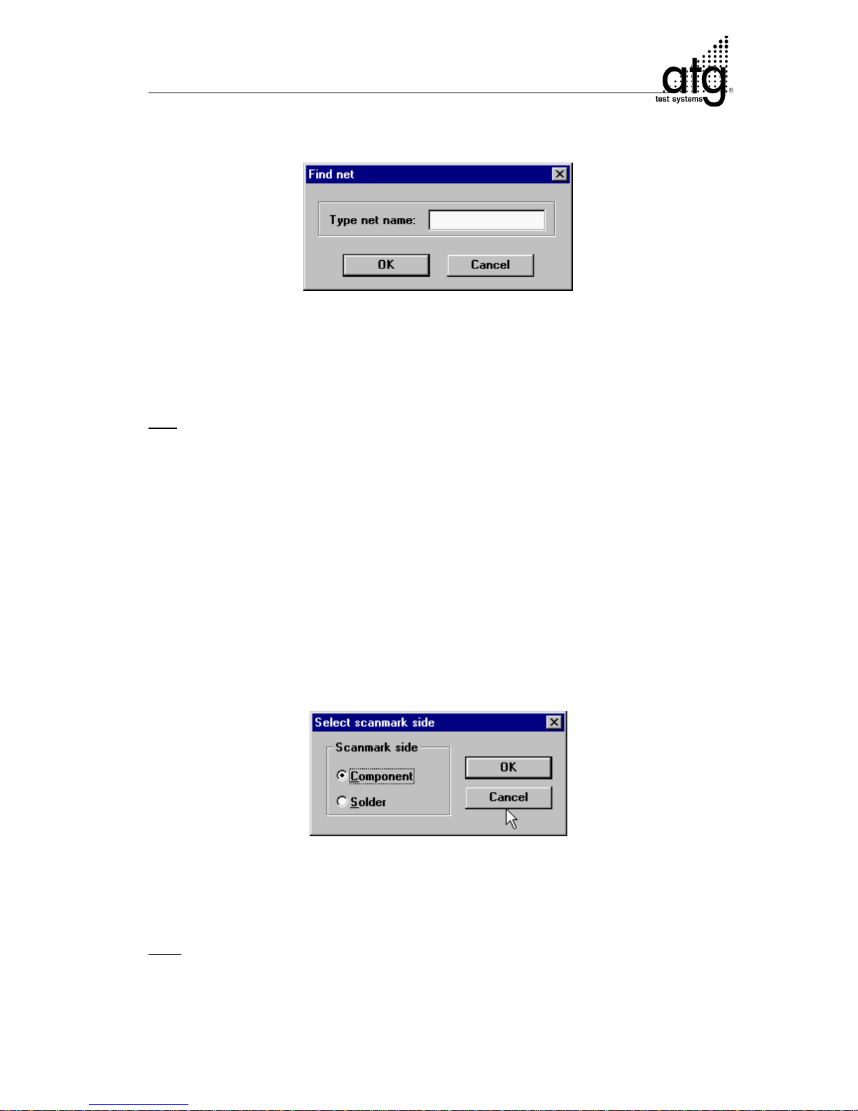
C-29
Supervisor Mode A 3 V3.7
Find Net
Input window Find Net
For finding a certain net on the board. In the displayed input window enter the wanted
net number. In the graphic, auxiliary lines connect all pads of the net and the net
information appears in the info bar.
Hint:
In the fault printout of a multi-panel the net numbers of panel 2 fol. are given with their
ATF-net number. These nets are displayed in the first panel, if you would like to display
them. You can then select the desired panel via the pad-ID of the fault printout.
Add Scanmark
For placing scanmarks. This function is only visible if not all scanmarks are set.
Position the cursor on the test pad, which you would like to define as a scanmark.
Press the left mouse-button and select Add Scanmark.
For through hole pads the window Select scanmark side appears if a scanmark can
be placed on either side:
Select scanmark type
Select the board side and confirm with OK. The scanmark appears as colored symbol
on the test pad.
Hint:
When placing scanmarks observe that they are positioned within the camera range,
otherwise the scanning process is not started.
Page 75

C-30
Supervisor Mode A 3 V3.7
Delete Scanmarks
With the menu item Delete Scanmarks you can erase set marks. Position the cursor
on the scanmark to be erased, click the left mouse-button and select Delete Scanmark.
The scanmark symbol on the test pad is deleted.
7.8.5.2 The Functions of the Pop up menu outside of Test
Pads
Zoom Reset
Image filling view of the test area; the test area is centered.
Zoom In
Magnifies the current view by the factor 2. The center remains center of the current
window.
Zoom Out
Reduces the view by the factor 2.
Zoom Select
Enables a user defined image section. After selecting this function the cursor appears
as a reticule. With the left mouse-button place this reticule at a random position and
keep the mouse-button pressed. Pull a frame around the section to be enlarged.
Zoom Undo
Undoes the last zoom action.
Distance
Distance enables the measurement certain stretches.
The cursor adopts the shape of an arrow-symbol. Place the tip of the arrow on the origin
of your measurement. Click and keep the left mouse-button pressed and move the
cursor to the second measuring point. The measurement value is continuously
displayed online, in the right of the info bar.
The measurement is displayed in 1/100 mm units. The measuring result displays the
distance between the original and the final position in XY-coordinates.
Example:
dx: 114 dy: 465
Page 76
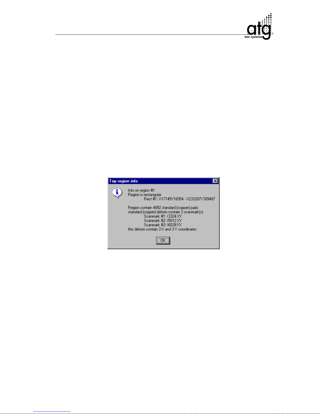
C-31
Supervisor Mode A 3 V3.7
The measured pads show a distance of 1.14 mm in X-direction and 4.65 mm in Ydirection between each other.
The next mouse click deletes the measuring result in the info bar.
Fast Move
Fast Move (or the M-key) enables you to move the zoomed section without changing
the zoom-factor (helpful for placing/deleting scanmarks).
For this purpose, a view of the entire test area is displayed. The zoomed section is
surrounded by a white rectangle and can be moved across the entire display. Click the
left mouse-button when the desired section is reached.
Top (bottom) region info
Opens the window T op region info or Bottom region info with informations about the
choosen region.
Info on region #1: Informations refer to region1
Region is rectangular Rect #1 X17145Y16954
•
X122187Y309487:
Corner coordinates of region
Region contains 4892 standard pads: Region has 4892 pads
Standard deform contain 3 scanmarks: Region has 3 scan marks
Scanmark #1: I3324XY: Scan mark pad 1
Scanmark #2: I5012XY: Scan mark pad 2
Scanmark #3: I6039XY: Scan mark pad 3
This deform contains 3 X and 3 Y coordinates: Number of used coordinates
Divide top region
For placing more than 4 scanmarks on a board’s component side. This function works
only if the cursor is located on panel 1.
The sections in which the scanmarks are to be placed can be randomly defined. After
calling up the function Divide top region the window Divide Region appears:
Page 77
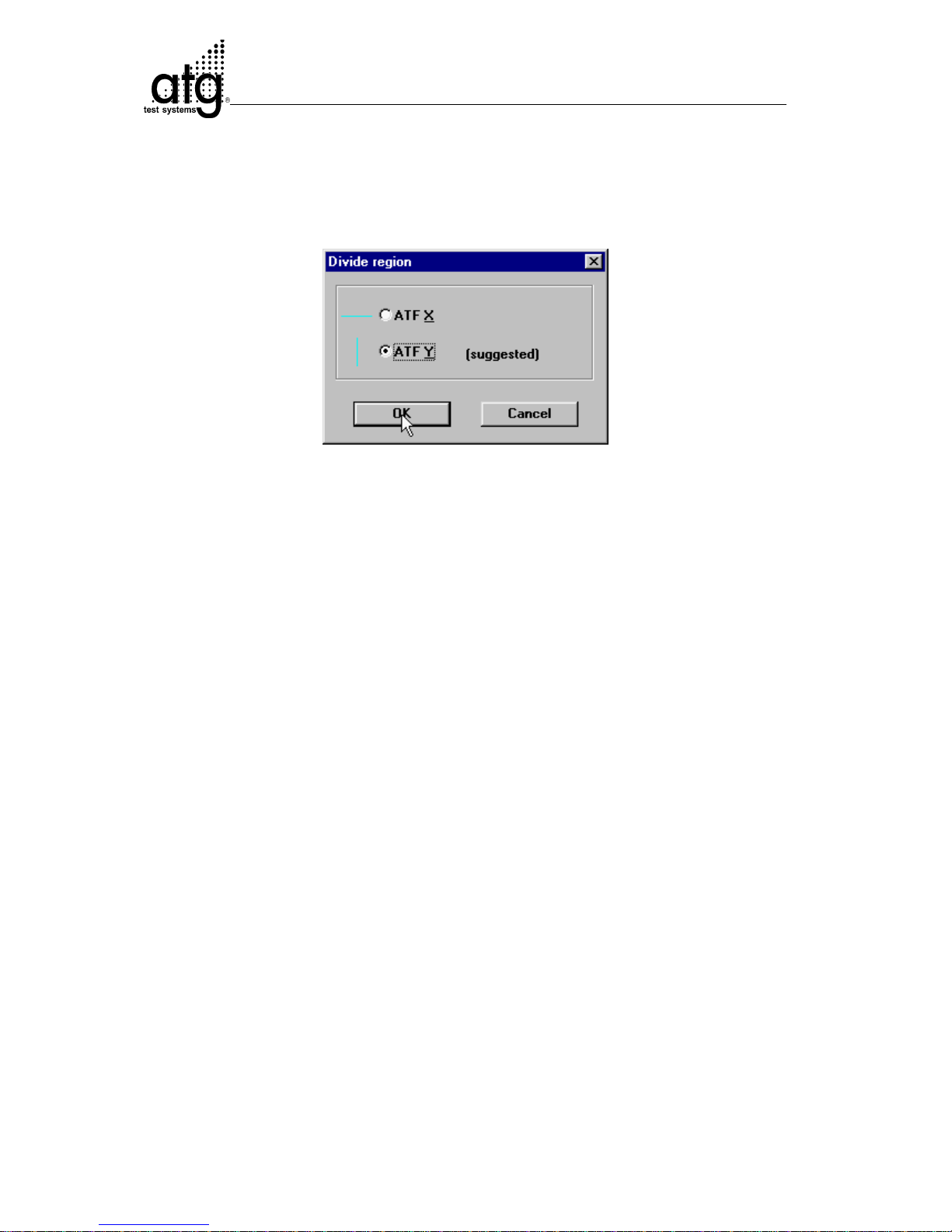
C-32
Supervisor Mode A 3 V3.7
This function is especially helpful if several boards are fastened in the shuttle and
scanmarks are to be placed individually on each board, or for the separate scanning
of high pitch areas, or also for trapezoid distortions on multi-samples.
Set dividing line
Here, you must select whether the scanmark area is to be divided vertically or
horizontally. The test system suggests dividing the longer side. Consequently, 2-4
scanmarks must be placed in the defined regions.
Divide bottom region
For placing more than 4 scanmarks on a board’s solder side.
The function operates similar to the above-described function Divide top region.
Connect (top/bottom) Region
The regional division can be undone by clicking on one region dividing line with the
right mouse-button. The function Connect (top/bottom) Region appears with which
the dividing line is removed. Placed surplus scanmarks are automatically removed.
Page 78
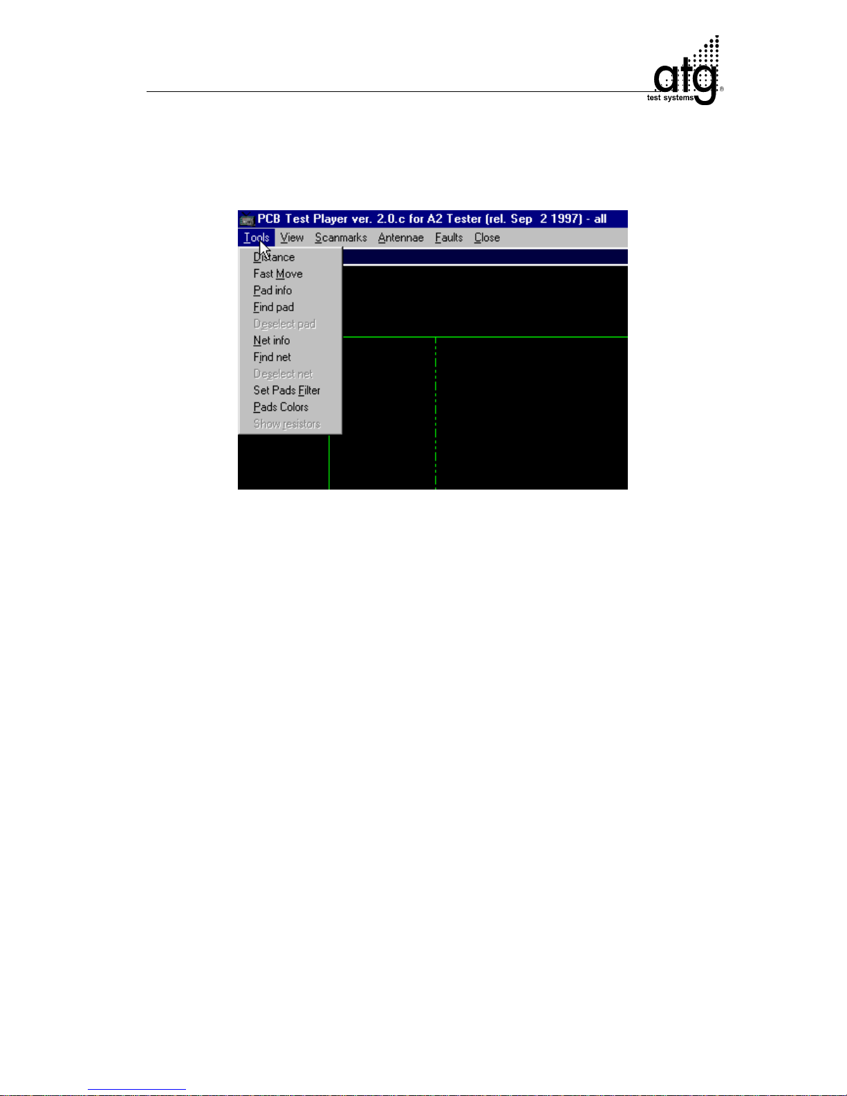
C-33
Supervisor Mode A 3 V3.7
7.8.6 The Main Menu Tools
Main menu tools of the sub-program Show <boardname>
The following functions are available in the main menu Tools
- Distance (also included in the pop up menu of the right mouse button)
- Fast Move (also included in the pop up menu of the right mouse button)
- Pad Info (also included in the pop up menu of the right mouse button)
- Find Pad (also included in the pop up menu of the right mouse button)
- Deselect Pad
- Net Info (also included in the pop up menu of the right mouse button)
- Find Net (also included in the pop up menu of the right mouse button)
- Deselect Net
- Set Pads Filter
- Pad Colors and
- Show Resistors
Most functions are also available via the pop up menu of the right mouse-button. Zoom
functions are only available via the right mouse-button. They are described in the
previous chapter The Functions of the Pop up Menu.
Page 79
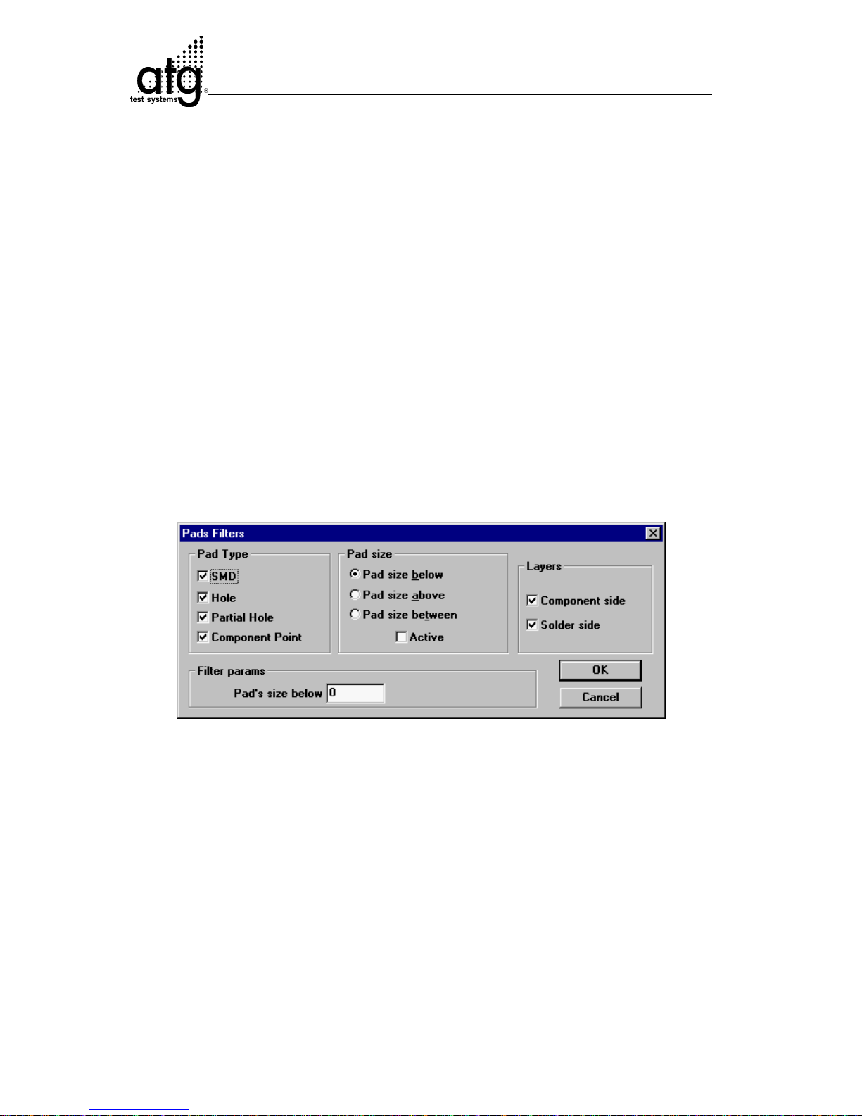
C-34
Supervisor Mode A 3 V3.7
Additional functions of the main menu DPS are:
7.8.6.1 Deselect Pad
The menu item Deselect Pad is only active if a test pad was selected with Find Pad.
With it you can remove the reticule from the selected pad.
7.8.6.2 Deselect Net
The menu item Deselect Net is only active if a test pad was selected with Net Info. You
can now delete the symbolic net connection from the graphic.
7.8.6.3 Set Pads Filter
The settings of the menu item Set Pads Filter enable you to define the displayed pads.
Pad Selection with Pad Filters
The Pads Filter-window provides the following functions:
Pad Type
With the filter function Pad Type you can display the following pad types in the graphic:
- SMD Show or hide SMD-pads
- Hole Show or hide through holes
- Partial Hole Show or hide partial through holes
- Component Point Show or hide component points
Page 80

C-35
Supervisor Mode A 3 V3.7
Pad Size
Filter function for selecting pad types of a certain size (Unit: 1/100mm).
This function uses the value of the input line Filter Params (Pad size below) as
reference value, displayed in the bottom of this window. The following filters are
available:
- Pad size below Show all pads that are smaller than the entered value.
- Pad size above Show all pads that are greater than the entered value.
- Pad size between Show all pads which located in-between the entered values. A
second input box is displayed for entering the filter parameters.
Hint:
The set Pad size-functions only come into effect after option Active is checked-off.
Layers
Filter for showing and hiding entire layers in the graphic.
- Component side Show or Hide the component side.
- Solder side Show or Hide the solder side.
Hint:
You can also use this filter when placing the scanmarks. This filter may also be useful
in connection with the functions Pad Info and Net Info.
For selecting a pad of the solder side, which is covered, by a component side pad, only
the pad of the component side is displayed. In this case, hide the component side.
7.8.6.4 Pad Color
The menu item Pad Colors lets you assign colors for the display of the different pad
types.
Page 81
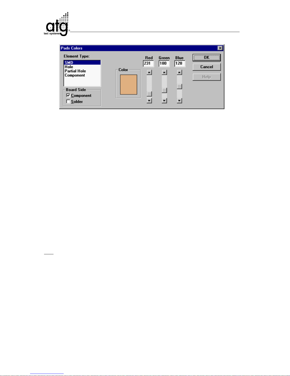
C-36
Supervisor Mode A 3 V3.7
Pad Color Assignments
In the function Element Type select the pad type to which you would like to assign a
different color and then select the board side for the color assignment (component- or
solder side).
For adjusting the color, three sliding controllers are available. Every color has 255
brightness levels, which may be combined with each other as desired. The color box
displays the currently adjusted color combination.
The individual adjustment options of the Pad Colors-window:
Element Type:
- SMD Color selection for the display of SMDs
- Hole Color selection for the display of through holes
- Partial Hole Color selection for the display of partial through holes
- Component Pad Color selection for the display of component pads
Board Side:
- Component Color setting for the selected pad type for the component side
- Solder Color setting for the selected pad type for the solder side
Hint:
For Hole-pads select the same color for component and solder side, since you are
dealing with one and the same pad. For this purpose, activate both layers (Component
and Solder) during the color assignment.
7.8.6.5 Show Resistors
Resistors defined between individual nets in the net list are displayed as red connection
lines between the origins of the corresponding net. With the menu item Show
Resistors you can either show or hide the resistor display.
Page 82
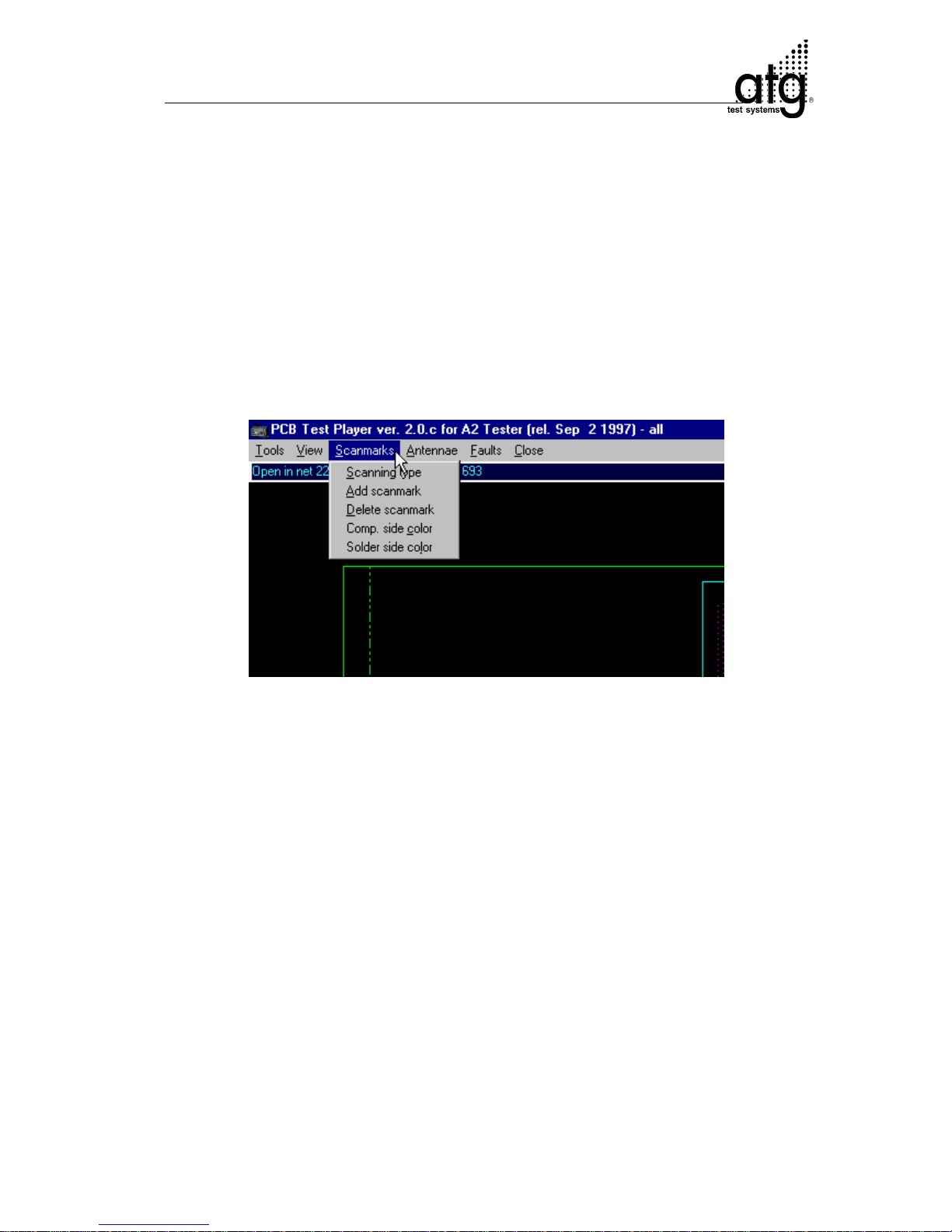
C-37
Supervisor Mode A 3 V3.7
7.8.7 Main Menu View
In the main menu View you can either show or hide the display of the outer layers. The
menu item Both sides shows both layers. The menu item Top only shows only the
component side and the menu item Bottom only exclusively the solder side.
7.8.8 Main Menu Scanmarks
Main Menu Scanmarks
In the Scanmarks-main menu you can define, delete and edit scanmarks.
7.8.8.1 Scanning Type
With the menu item Scanning Type you can open the selection window Scanning
type. With the available options you define how the board is to be scanned.
Usually, the definition of the scanmarks is already carried out in the DPS-station.
Provided that the board is not available at the DPS, the defined scanmarks may be
unfavorable (e.g. the real pad size does not correspond to the data or the board offset
requires scanmarks in other sections).
A combination of different variants is possible.
The following scanning types are available per test layer:
Page 83
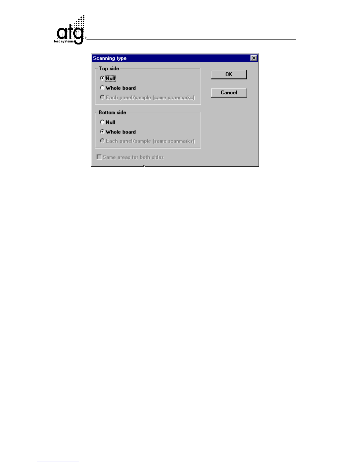
C-38
Supervisor Mode A 3 V3.7
Main Menu Scanmarks
- Null No scanning
- Whole board You can place 2,3 or 4 scanmarks on a single panel or a multi
sample. The number of scanmarks is calculated per section.
(Division in sections see Chapter “Pop up Menu outside of
pads”)
- Each panel/sample For multi samples you can place 2,3 or 4 scanmarks on every
single panel. It is sufficient to place the scanmarks on one
panel. A blue frame surrounds this panel.
The scanmarks must be:
1. as far outside as possible
2. as far apart from each other as possible
3. on small pads
4. on unmistakably pads
Fiducial-pads for pick and place machines are suitable.
7.8.8.2 Add Scanmark
With the menu item Add scanmark, you can set additional scanmarks. The cursor
adopts the shape of the scanmark symbol with a plus sign and the scanmarks can
be placed. T wo to four scanmarks can be placed per region.
Place the scanmark symbol on the test pad to be defined as scanmark. For a
through hole selected, the window Select scanmark type appears for selecting the
side of the scanmark.
Page 84
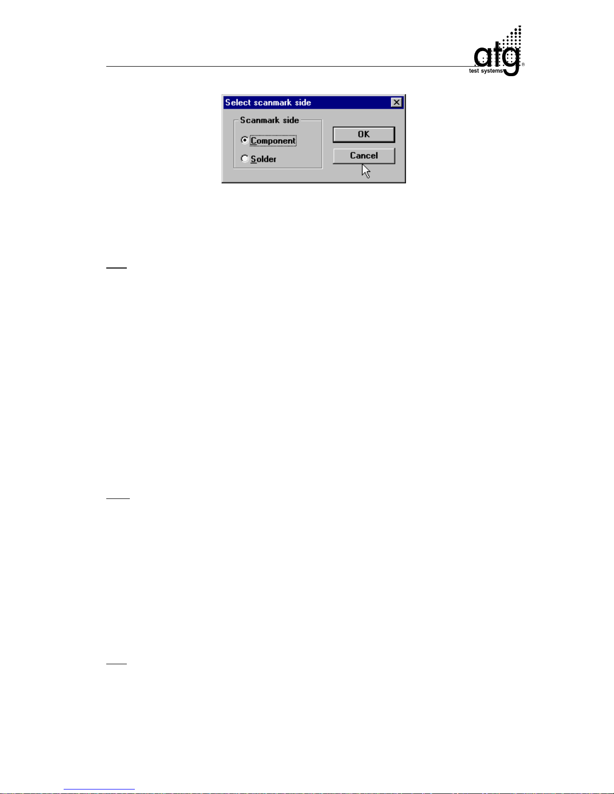
C-39
Supervisor Mode A 3 V3.7
Select scanmark side
The set scanmark appears as colored symbol on the test pad.
Hint:
In the graphic sub-program you at all times have access to the Add Scanmarkcommand via the right mouse-button if the cursor is positioned on a test pad. However,
this is only possible if not all 4 scanmarks (per section) are placed.
One of the 4 following reasons might explain why it is impossible to place a scanmark
on a test pad:
1. Scanning Type for this layer is set to Null
2. All scanmarks for this layer are already placed.
3. The selected test pad is located on the solder side and is covered in the graphic by
a component side test pad.
4. The selected test pad is located on the wrong panel (for Scan each Panel)
The following warning is displayed when leaving the graphic, if less than 2 scanmarks
(per section) are set:
Numbers of scanmarks are invalid!
Hint:
When placing scanmarks observe that the scanmarks are set within the camera range,
otherwise the scanning process is not started.
7.8.8.3 Delete Scanmarks
With the menu item Delete Scanmarks you can erase scanmarks. After the function
is activated, the cursor adopts the shape of a scanmark symbol with a minus sign.
Position the cursor on the scanmark to be deleted and click the left mouse-button. The
scanmark symbol on the test pad is erased.
Hint
:
At all times, you have access to the Delete Scanmarks-command via the right mousebutton, if the cursor is positioned on a scanmark.
Page 85
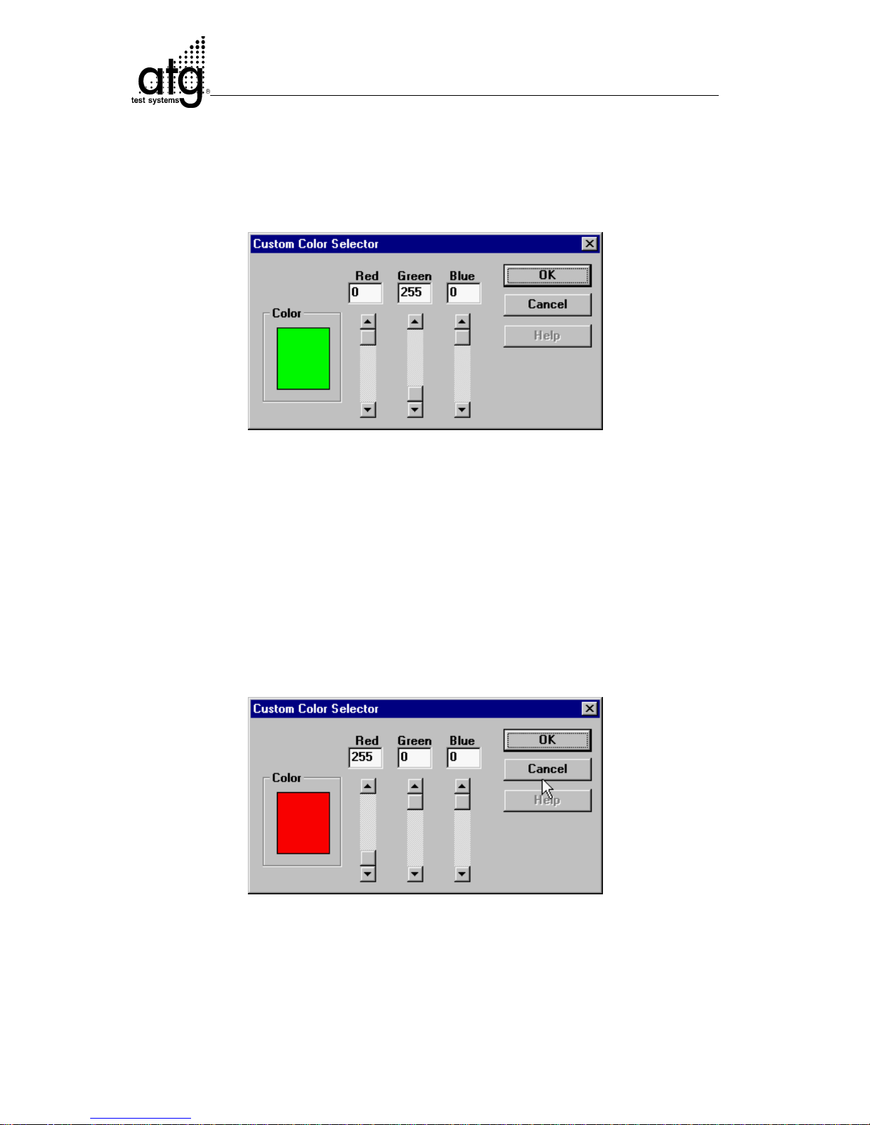
C-40
Supervisor Mode A 3 V3.7
7.8.8.4 Comp. Side Color
With the menu item Comp. Side Color you can define the color in which the
scanmarks of the component side are to be displayed.
Color Selection for component side pads
For adjusting the color three slide controllers are available. Every color has 255
brightness levels, which can be combined with each other as desired. The Color-box
displays the currently adjusted color.
7.8.8.5 Solder Side Color
The menu item Solder Side Color lets you define the color in which the scanmarks
of the solder side are to be displayed in.
Color Selection for solder side pads
For adjusting the color three slide controllers are available. Every color has 255
brightness levels, which can be combined with each other as desired. The Color-box
displays the currently adjusted color.
Page 86
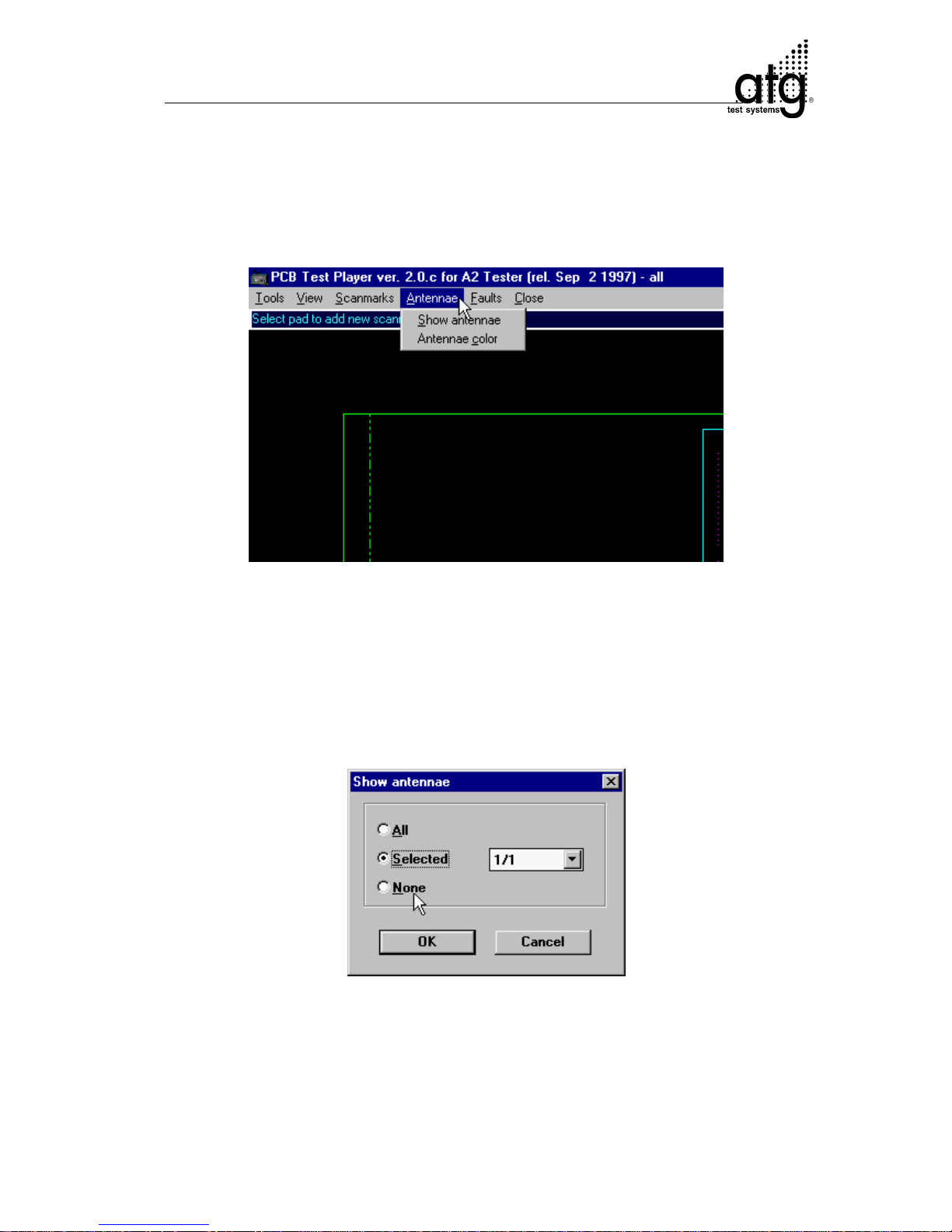
C-41
Supervisor Mode A 3 V3.7
7.8.9 Main Menu Antennae
In the main menu Antennae you can both display antennae and adjust their color.
Main Menu Antennae
7.8.9.1 Show antennae
With the menu item Show antennae you can display the DPS generated antennae
nets.
Show Antennae
With the option All you can show all antennae. With the option Selected you can show
a certain antennae. For this purpose, use the scroll-bar at the right.
Page 87

C-42
Supervisor Mode A 3 V3.7
Example:
2/1 = 2. Antennae net for panel 1
The option None hides the antennae.
7.8.9.2 Antennae Color
With the menu item Antennae Color you can define the color in which the antennae
are to be displayed in.
Color Selection for the Antennae Display
For adjusting the color three slide controllers are available. Every color has 255
brightness levels, which can be combined with each other as desired. The Color-box
displays the currently adjusted color.
Page 88
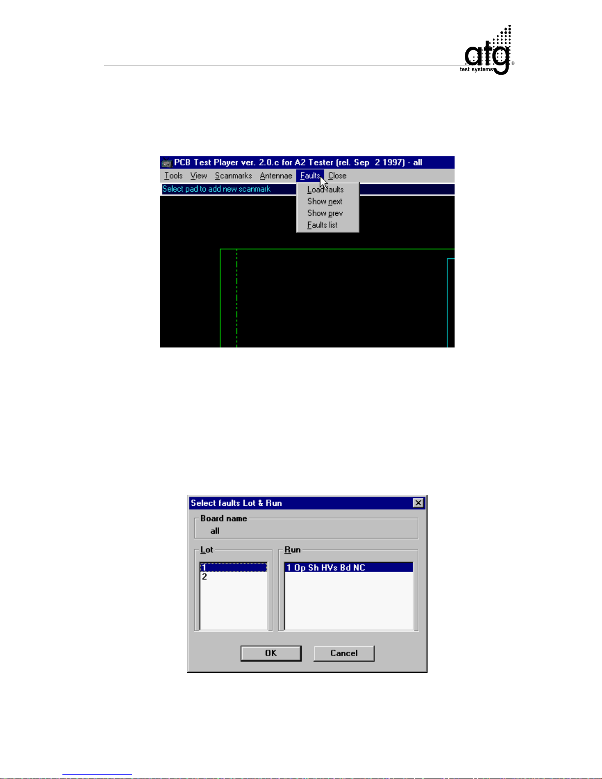
C-43
Supervisor Mode A 3 V3.7
7.8.10 Main Menu Faults
In the main menu Faults you can graphically display faults.
Main Menu Faults of the sub-program Show <boardname>
7.8.10.1Load Faults
With the menu item Load Faults you can load faults for graphically displaying them.
In the appearing selection window Select faults Lot & Run select the test run to be
displayed. The faults included in the faults file are shown abbreviated in the list.
Load Fault File
Page 89

C-44
Supervisor Mode A 3 V3.7
The first fault of the test run is immediately shown in the screen and the corresponding
fault information is displayed in the info line in the left. A yellow line for an existing open
or a short connects both fault pads. The pads are highlighted in green for faults like No
contact or Bad Field.
Hint:
The program displays the following text if no fault could be detected in the file of the
selected test run:
No Faults in selected lot or run
7.8.10.2Show next
With the menu item Show next you can view the next fault of the faults list. The plus
sign (+) serves as hot key for the same purpose.
If the end of the list is reached, the following message appears:
No more faults in fault-file
.
After confirming this message, the program returns to viewing the first fault.
7.8.10.3Show Prev
With the menu item Show prev you can return to viewing the previous fault of the faults
list. The minus sign (–) serves as hot key for the same purpose.
If the end of the list is reached, the following message appears:
No more faults in fault-file
.
After confirming this message the program returns to viewing the last fault.
7.8.10.4Faults List
With the menu item Faults List you can view the faults list loaded with Load Faults
and display individual faults.
In the bottom of the Faults list-window all possible fault types of the loaded run are
displayed. A fault type not present in the fault file is displayed in gray. In the selection
box Panel you can choose for multi samples which panel’s faults you would like to
show.
The upper part of the selection window shows the individual faults of the activated fault
types. By clicking on the appropriate line of the faults list you can display any desired
fault. The fault is immediately shown in the window. Move the Faults list-window to
the side in order to view the board display.
It is impossible to print out the contents of the faults list or to actualize them.
Page 90
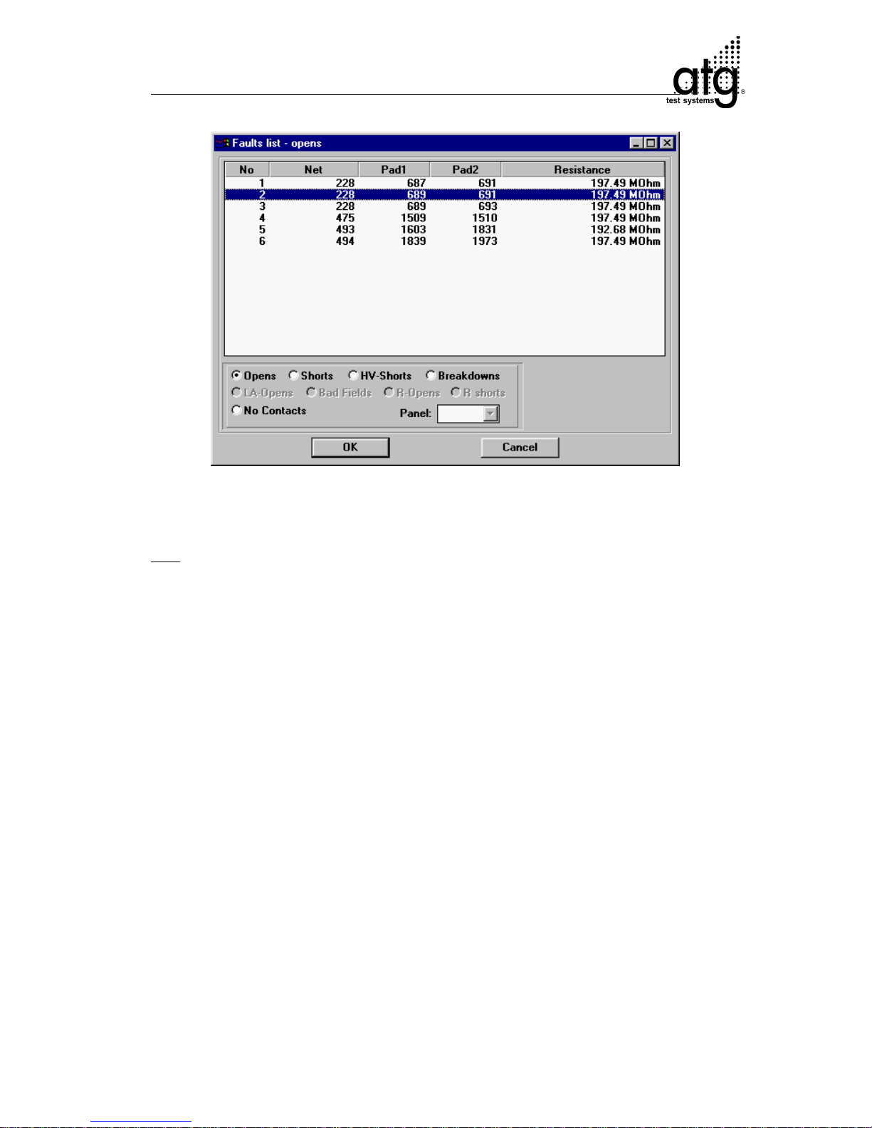
C-45
Supervisor Mode A 3 V3.7
Selects Faults for Display
Hint:
atg test systems offers the option "verification mode". This expansion of the TestPlayer
has extensive possibilities to verify faults from flying probe and grid test systems.
Page 91
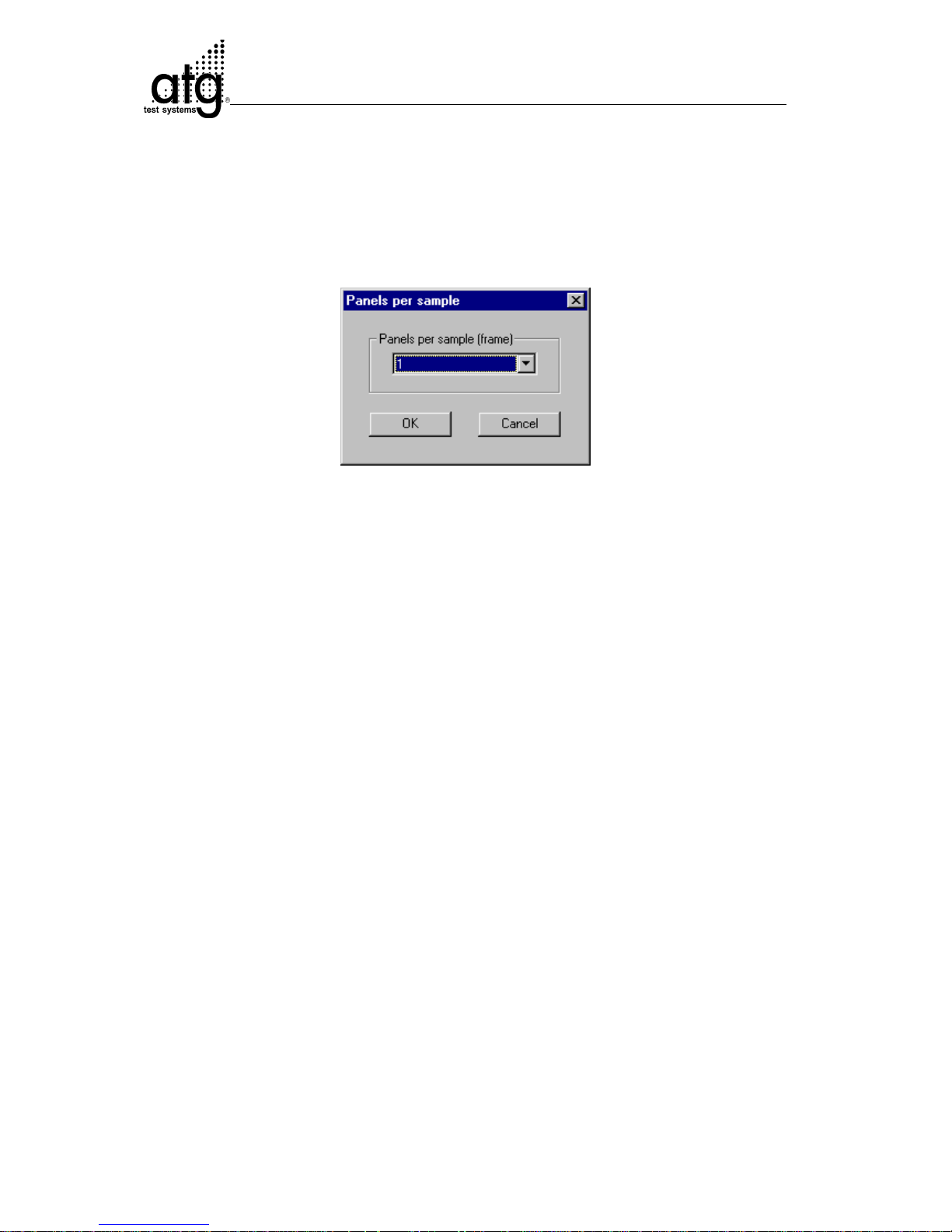
C-46
Supervisor Mode A 3 V3.7
7.8.11 Main menu Markers
With the menu Markers you can define the number of printer marks. Not available for
manual test system.
7.8.11 The Main Menu Item Close
With a mouse click on the menu item Close you switch back to the supervisor mode
work window.
Page 92
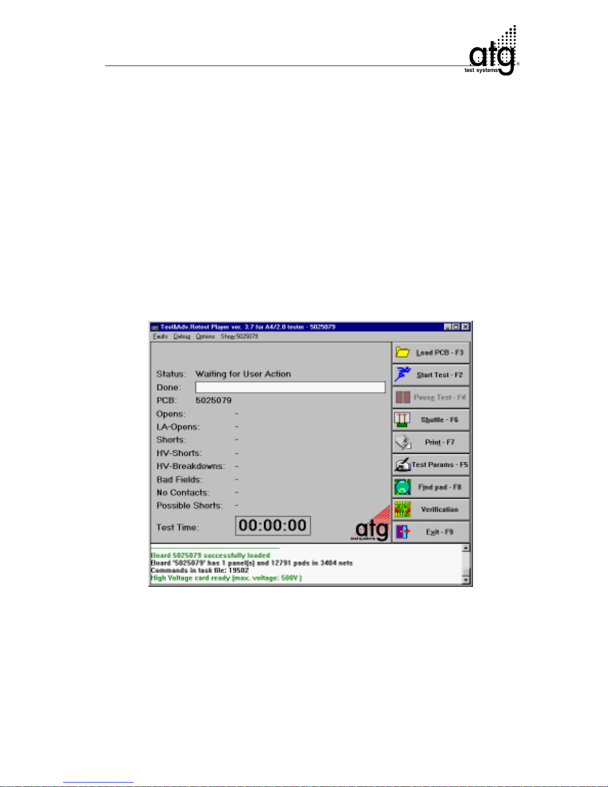
C-47
Supervisor Mode A 3 V3.7
7.9 Action Buttons of the Supervisor Mode
The supervisor mode provides 8 buttons associated with the function keys F2
through F9. The buttons F2 through F7 have the same functions as in the user
mode. Additionally, the buttons Step by Step (F8) and Exit (F9) are available.
The functions of the T est Params (F5) button are greatly expanded in the super-
visor mode. In the user mode, only the tab box Skip Panels is available for multipanels.
In the supervisor mode, you can change the Z-axis parameters during the test run.
For this purpose, first press the button Pause Test (F4). With the button Test
Params (F5), you can then edit the Strokes parameter settings. After the desired
settings were made, press the OK-button to confirm the modifications. Testing is
continued with Resume T est (F4).
Button
Find Pad (F8)
With the button Find pad, you can find individual pads on the board with the
camera or contact them with a test probe. The board must have been scanned
before; otherwise, this menu item cannot be started. For the opposite case, the
board is first scanned automatically after the function Find pad is executed.
Page 93

C-48
Supervisor Mode A 3 V3.7
Exit (F9)
The Exit (F9) button closes the T estPlayer.
Hint:
The option button verification is only availably if the erscheint nur, wenn der dafür
benötigte Dongle aufgesteckt ist.
Page 94
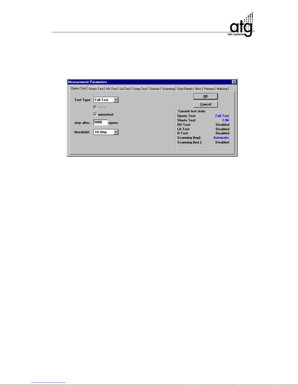
C-49
Supervisor Mode A 3 V3.7
7.9.1 Button Test Params (F5)
The settings of the Test Params-button define the conditions for the test procedure.
Opening window Test Params
The Current test state, a summary of all important parameters in their current status,
is displayed in the bottom right for all menu items of the Measurement Parameters-
window.
Page 95
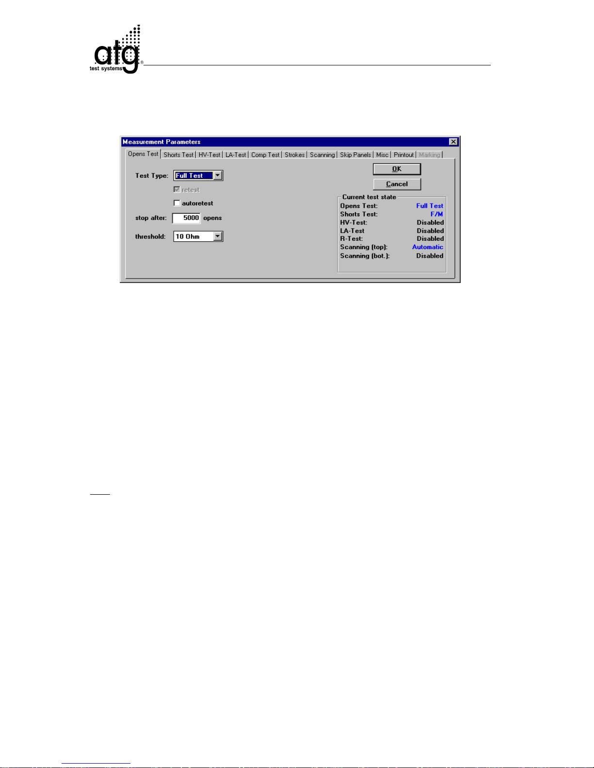
C-50
Supervisor Mode A 3 V3.7
7.9.1.1 The Parameter-Menu Opens Test
Parameter-Menu Opens Test
The tab box Opens T est specifies the settings for the Opens Test.
– Test type
Full test Opens test enabled
Disable Opens test disabled
Auto Retest Opens test, retesting only detected opens. The only require-
ment is an existing faults file of the board including the
opens data.
Combined Enables the combined test method, prepared in DPS. Opti-
on for test system A3. Opens and shortstest in 1 test run.
Approx. 10% faster test.
Hint:
Disabling the opens test simultaneously disables the shorts test. The opens test
must be enabled for being able to select further test types.
Retest Opens detected during the test are retested after test com-
pletion and are minimized if necessary . This function cannot
be turned off.
Auto retest Do not use this feature!
– Stop after....opens T esting is automatically canceled if the here entered value
of opens is obtained. For multi-panel testing, the panel is
automatically excluded from testing while testing continues
with the remaining panels.
– Threshold Here you can define the resistance value (in Ohms) for an
open to be detected. Default value 10 Ohm. (adjustable
range 1 Ohm - 1 kOhm)
Page 96
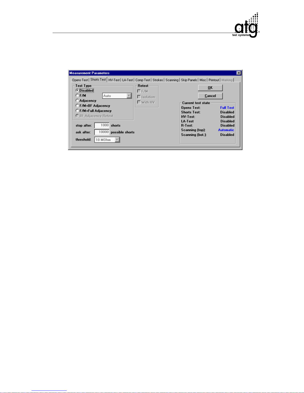
C-51
Supervisor Mode A 3 V3.7
7.9.1.2 The Parameter-Menu Shorts Test
Parameter-Menu Shorts Test
The tab box Shorts Test defines the settings for the shorts test.
Test type
– Disabled Shorts test disabled
– F/M Field Measurement
Shorts are determined via field-measurement. The retest is a resistance test.
- Adjacency Only functional with an existing adjacency-file. Shorts are exclusively
determined with the adjacency method.
- F/M + B/F Adjacency Field Measurement + Bad Field Adjacency
Only functional with an existing adjacency-file. Shorts are determined with the field
measuring method. Determined unclear measuring results of the types “Bad Field”
and “No Contact” are retested with help of the adjacency-file. “Possible Shorts” are
retested with the resistance method.
The retest results of the field measurement and the comparisons with the adjacencyfile are added.
- F/M + Full Adjacency Field Measurement + Full Adjacency
Only functional with an existing adjacency-file. Shorts are determined with the field
measuring method. Determined unclear measuring results of the types “Bad Field”
and “No Contact”, as well as “Possible Shorts” from the field measurement are
compared with the possible shorts of the adjacency-file. They are retested if they
exist in both lists.
Page 97
C-52
Supervisor Mode A 3 V3.7
Possible shorts found with the field measurement are not retested if they are not
included in the adjacency-file.
Shorts clearly detected with the field measurement (Short to antennae) are put out
even if they are not included in the adjacency-file.
– BF Adjacency
Retest In an open auto retest all bad fields are retested.
Auto
The test systems chooses automatically from following test methods:
Double F/M, Single F/M, Parallel F/M or One antennae parallel F/M.
Measur-
ment
All
antennae1antenna
2 points
per net
1 point
per net
Parallel
contacting
Double
F/M
X X
Single
F/M
X X
Parallel
F/M
X XX
One ant.
(par.)
F/M
XXX
This menu can be limited because of limited DPS preparation. The items Parallel
F/M and One antennae parallel F/M is only available with existing EPS-data.
The setting to Auto is normally recommended. During the first run of a job the test
system calculates the best test method for the following tests of this board type and
switches to this method.
– Stop after....shorts Testing is automatically canceled after the here entered
value of shorts per panel is passed.
– Ask after....possible shorts Testing is automatically paused after the here entered
value of shorts per panel is passed. The user then has the option of canceling the
test.
Page 98

C-53
Supervisor Mode A 3 V3.7
– Threshold Here, you can define up to which resistor value (in Ohms) a short is
detected. Standard value 10 MOhm.
(Adjustable range 0.5 MOhm - 10 MOhm)
Retest
– F/M This option cannot be disabled.
If the test system receives insufficient measuring results from the field measurement,
nets with contradictory measuring results are automatically retested (Field-Retest).
– Isolation This option cannot be disabled
Ohmic retest between the possible shorts detected in the field measurement.
–
With HV This option cannot be disabled
Retest is carried out with high voltage.
Page 99
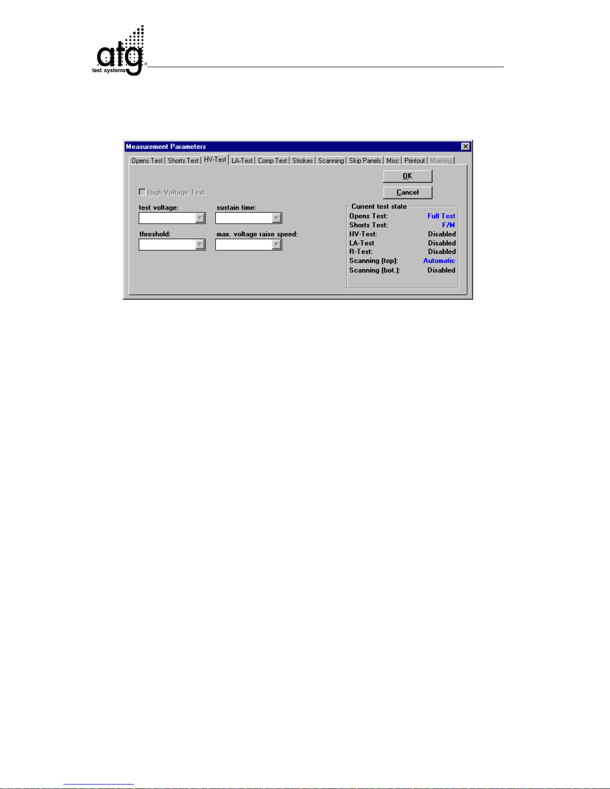
C-54
Supervisor Mode A 3 V3.7
7.9.1.3 The Parameter-Menu HV-Test
Parameter-menu HV-Test
The tab box HV-Test (High-Voltage-test) defines the settings for the high voltage
test.
These options are only available if the DPS generated an HV-test.
– High-Voltage HV test en/disabled
– T est voltage T est voltage of the HV -Test. Default value 250 V (ad-
justable range 25V - 250V / 500V , depending measuring card).
– Sustain time Voltage application time
– Threshold Here, you can define below which resistor value (in
Ohms) a connection is detected as an HV short. Default value 100 MOhm. (adjustable range 5 MOhm 100 MOhm)
– Max voltage
– raise speed Increase of the voltage
Page 100
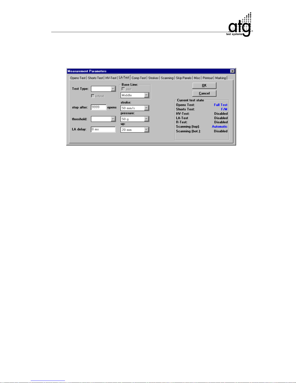
C-55
Supervisor Mode A 3 V3.7
7.9.1.4 Parameter-Menu LA-Test
Parameter-Menu LA-Test
– T est T ype LA-default test only with additional hardware.
– Stop after ...opens Testing is automatically canceled if the here entered value
of LA-opens per panel is obtained.
– Threshold Here, you define below which LA-value a connection is
intact.
– LA delay Time in milliseconds of LA-voltage application before te-
sting is started.
– Base line
Use
Select this function for calibrating with the base
line.
Middle
Base line selection.
– Stroke Test needle motion speed for the LA-test.
– Pressure Pressure applied by the probes on the contacted pad for the
LA-test. Default value: 30g. (adjustable range 10 g - 50g in
5 g-steps)
– Up Maximum stroke of the needles above the board during the
LA-test. Default value: 20 mm. (adjustable range 0.75 mm –
20 mm) The minimum stroke in a test run can be reduced to
1/3 of the set value. This value is shown underneath Min up.
The test system reduces the Z-axis stroke to the Min-up
value for increasing the test speed, only if the board topography allows this. This option can be disabled with the
setting PCB-Holder / Used of the parameter window Misc.
 Loading...