

Page 1
User Manual
CN-5000
2005-09-13
Page 2

CN-5000 User Manual
Regulatory Information
1. This is an FCC Class A product. In a domestic environment this product
may cause radio interference in which case the user may be required to
take adequate measures.
This equipment has been tested and found to comply with the limits for a
Class A digital device, pursuant to Part 15 of the FCC Rules. These limits
are designed to provide reasonable protection against harmful
interference when the equipment is operated in a commercial
environment. This equipment generates, uses and can radiate radio
frequency energy and, if not installed and used in acco rdan ce with th e
instruction manual, may cause harmful interference to radio
communications. Operation of this equipment in a residential area is
likely to cause harmful interference in which case th e us er will be
required to correct the interference at his own expens e.
2. All contents of this package, including products, packing materials and
documentation comply with ROHS.
ii
2005-09-13
Page 3

CN-5000 User Manual
User Notice
All information, documentation, and specifications contained in this manual
are subject to change without prior notification by the manufacturer. T h e
manufacturer makes no representations or warranties, either expressed or
implied, with respect to the contents hereof and specifically disclaims any
warranties as to merchantability or fitness for any particular purpose. Any of
the manufacturer’s software described in this man u al is so ld or licen s ed ‘as
is’. Should the programs prove defective following their purchase, the buyer
(and not the manufacturer, its distributor, or its dealer), assumes th e en tire
cost of all necessary servicing, repair and any incidental or consequential
damages resulting from any defect in the software.
The manufacturer of this system is not responsible for any radio and/or TV
interference caused by unauthorized modifications to this dev ice. It is the
responsibility of the user to correct such interference.
The manufacturer is not responsible for any damage incurred in the operation
of this system if the correct operational voltage setting was not selected prior
to operation. PLEASE VERIFY THAT THE VOLTAGE SETTING IS
CORRECT BEFORE USE.
2005-09-13
iii
Page 4

CN-5000 User Manual
Safety Instructions
General
w Read all of these instructions. Save them for future reference.
w Follow all warnings and instructions marked on the device.
w Do not place the device on any unstable surface (cart, stand, table, etc.). If
the device falls, serious damage will result.
w Do not use the device near water.
w Do not place the device near, or over, radiators or heat registers.
w The device cabinet is provided with slots and openings to allow for
adequate ventilation. To ensure reliable operation, and to protect against
overheating, these openings must never be blocked or covered.
w The device should never be placed on a soft surface (bed, sofa, rug, etc.)
as this will block its ventilation openings. Likewise, the device should not
be placed in a built in enclosure unless adequate ventilation has been
provided.
w Never spill liquid of any kind on the device.
w Unplug the device from the wall outlet before cleaning. Do not use liquid
or aerosol cleaners. Use a damp cloth for cleaning.
w The device should be operated from the type of power source indicated
on the marking label. If you are not sure of the type of power available,
consult your dealer or local power company.
w The device is equipped with a 3-wire grounding type plug. This is a
safety feature. If you are unable to insert the plug into the outlet, contact
your electrician to replace your obsolete outlet. Do not attempt to defeat
the purpose of the grounding-type plug. Always follow your
local/national wiring codes.
w Do not allow anything to rest on the power cord or cables. Route the
power cord and cables so that they cannot be stepped on or tripped over.
w If an extension cord is used with this device make sure that the total of the
ampere ratings of all products used on this cord does not exceed the
extension cord ampere rating. Make sure that the total of all products
plugged into the wall outlet does not exceed 15 amperes.
iv
2005-09-13
Page 5

CN-5000 User Manual
w To help protect your system from sudden, transient increases and
decreases in electrical power, use a surge suppressor, line conditioner, or
un-interruptible power supply (UPS).
w Position system cables and power cables carefully; Be sure that nothing
rests on any cables.
w When connecting or disconnecting power to hot-pluggable power
supplies, observe the following guidelines:
§ Install the power supply before connecting the power cable to the
power supply.
§ Unplug the power cable before removing the power supply.
§ If the system has multiple sources of power, disconnect power from
the system by unplugging all power cables from the power supplies.
w Never push objects of any kind into or through cabinet slots. They may
touch dangerous voltage points or short out parts resulting in a risk of fire
or electrical shock.
w Do not attempt to service the device yourself. Refer all servicing to
qualified service personnel.
w If the following conditions occur, unplug the device from the wall outlet
and bring it to qualified service personnel for repair.
§ The power cord or plug has become damaged or frayed.
§ L iquid has been spilled into the device.
§ T h e dev ice has been ex posed to rain or water .
§ The device has been dropped, or the cabinet has been damaged.
§ T he device exhibits a distinct change in performance, indicating a
need for service.
§ T h e dev ice does not oper ate normally when th e oper atin g in str uctio ns
are followed.
w Only adjust those controls that are covered in the operating instructions.
Improper adjustment of other controls may result in damage that will
require extensive work by a qualified technician to repair.
v
2005-09-13
Page 6

CN-5000 User Manual
Rack Mounting
w Before working on the rack, make sure that the stabilizers are secured to
the rack, extended to the floor, and that the full weig ht of th e rack res ts on
the floor. Install front and side stabilizers on a single rack or front
stabilizers for joined multiple racks before working on the rack.
w Always load the rack from the bottom up, and load th e heav ies t item in
the rack first.
w Make sure that the rack is level and stable before extending a dev ice from
the rack.
w Use caution when pressing the device rail release latches and sliding a
device into or out of a rack; the slide rails can pinch your fingers.
w After a device is inserted into the rack, carefully extend the rail into a
locking position, and then slide the device into the rack.
w Do not overload the AC supply branch circuit that provides power to the
rack. The total rack load should not exceed 80 percent of the branch
circuit rating.
w Ensure that proper airflow is provided to devices in the rack.
w Do not step on or stand on any device when servicing other devices in a
rack.
vi
2005-09-13
Page 7

CN-5000 User Manual
Package Contents
The complete CN-5000 package consists of:
w 1 CN-5000 KVM on the Net™ Control Unit
w 1 Custom KVM Cable Set
w 1 Power Adapter
w 1 Rack Mount Kit
w 1Software CD
w 1 User Manual
w 1 Quick Start Guide
Check to make sure that all the components are present and that nothing was
damaged in shipping. If you encounter a problem, contact your dealer.
Read this manual thoroughly and follow the installation and operation
procedures carefully to prevent any damage to the unit, and/or any of the
devices connected to it.
© Copyright 2005 ATEN® International Co., Ltd.
Manual Part No. PAPE-0255-100G
Printed in Taiwan 09/2005
All brand names and trademarks are the registered property of their respective owners.
2005-09-13
vii
Page 8

CN-5000 User Manual
Contents
Regulatory Information . . . . . . . . . . . . . . . . . . . . . . . ii
User Notice . . . . . . . . . . . . . . . . . . . . . . . . . . . . . . iii
Safety Instructions . . . . . . . . . . . . . . . . . . . . . . . . . . iv
General . . . . . . . . . . . . . . . . . . . . . . . . . . . . . . iv
Rack Mounting . . . . . . . . . . . . . . . . . . . . . . . . . vi
Package Contents . . . . . . . . . . . . . . . . . . . . . . . . . . . vii
About This Manual . . . . . . . . . . . . . . . . . . . . . . . . . . xi
Overview . . . . . . . . . . . . . . . . . . . . . . . . . . . . . xi
Conventions . . . . . . . . . . . . . . . . . . . . . . . . . . . xii
Getting Help . . . . . . . . . . . . . . . . . . . . . . . . . . . . . xii
1. Introduction
Overview . . . . . . . . . . . . . . . . . . . . . . . . . . . . . . . . 1
Features . . . . . . . . . . . . . . . . . . . . . . . . . . . . . . . . . 3
System Requirements . . . . . . . . . . . . . . . . . . . . . . . . . 4
2. Hardware Setup
Front View . . . . . . . . . . . . . . . . . . . . . . . . . . . . . . . 5
Rear View . . . . . . . . . . . . . . . . . . . . . . . . . . . . . . . 6
Before You Begin . . . . . . . . . . . . . . . . . . . . . . . . . . . 7
Rack Mounting . . . . . . . . . . . . . . . . . . . . . . . . . . . . . 7
Cable Information . . . . . . . . . . . . . . . . . . . . . . . . . . . 8
Installation . . . . . . . . . . . . . . . . . . . . . . . . . . . . . . . 9
3. Getting Started
Logging In . . . . . . . . . . . . . . . . . . . . . . . . . . . . . . 11
Screen Elements . . . . . . . . . . . . . . . . . . . . . . . . . . . 14
4. Administration
Introduction . . . . . . . . . . . . . . . . . . . . . . . . . . . . . . 15
General . . . . . . . . . . . . . . . . . . . . . . . . . . . . . . . . 16
Network . . . . . . . . . . . . . . . . . . . . . . . . . . . . . . . 17
Access Port . . . . . . . . . . . . . . . . . . . . . . . . . . . . 17
IP Address . . . . . . . . . . . . . . . . . . . . . . . . . . . . 18
DNS Server . . . . . . . . . . . . . . . . . . . . . . . . . . . 18
Log Server . . . . . . . . . . . . . . . . . . . . . . . . . . . . 18
Security . . . . . . . . . . . . . . . . . . . . . . . . . . . . . . . . 19
Filtering . . . . . . . . . . . . . . . . . . . . . . . . . . . . . 20
viii
2005-09-13
Page 9

CN-5000 User Manual
Radius . . . . . . . . . . . . . . . . . . . . . . . . . . . . . . . . . 22
User Manager . . . . . . . . . . . . . . . . . . . . . . . . . . . . . 24
Customization . . . . . . . . . . . . . . . . . . . . . . . . . . . . 26
Firmware . . . . . . . . . . . . . . . . . . . . . . . . . . . . . . . 27
5. The Windows Client
Starting Up . . . . . . . . . . . . . . . . . . . . . . . . . . . . . . 29
Operation . . . . . . . . . . . . . . . . . . . . . . . . . . . . . . . 31
OSD Control Panel . . . . . . . . . . . . . . . . . . . . . . . . 31
Keystrokes . . . . . . . . . . . . . . . . . . . . . . . . . . . . 32
Mouse Synchronization . . . . . . . . . . . . . . . . . . . . . 32
Hotkeys . . . . . . . . . . . . . . . . . . . . . . . . . . . . . 34
Video Adjustment . . . . . . . . . . . . . . . . . . . . . . . . 36
6. The Java Client
Introduction . . . . . . . . . . . . . . . . . . . . . . . . . . . . . . 39
Operation . . . . . . . . . . . . . . . . . . . . . . . . . . . . . . . 41
The Toolbar . . . . . . . . . . . . . . . . . . . . . . . . . . . 41
7. The Log File
The Log File Screen . . . . . . . . . . . . . . . . . . . . . . . . . 45
8. AP Operation
The Administrator Utility . . . . . . . . . . . . . . . . . . . . . . 47
Installation . . . . . . . . . . . . . . . . . . . . . . . . . . . . 47
Starting Up . . . . . . . . . . . . . . . . . . . . . . . . . . . . 48
Logging In . . . . . . . . . . . . . . . . . . . . . . . . . . . . 50
The Settings Notebook . . . . . . . . . . . . . . . . . . . . . . 52
Uploading Changes . . . . . . . . . . . . . . . . . . . . . 53
General: . . . . . . . . . . . . . . . . . . . . . . . . . . . 54
Network: . . . . . . . . . . . . . . . . . . . . . . . . . . . 55
Security . . . . . . . . . . . . . . . . . . . . . . . . . . . 57
Filtering . . . . . . . . . . . . . . . . . . . . . . . . . . . 58
User Management . . . . . . . . . . . . . . . . . . . . . . 60
Customization . . . . . . . . . . . . . . . . . . . . . . . . 62
Upgrading the Firmware . . . . . . . . . . . . . . . . . . . . . 64
The Windows Client . . . . . . . . . . . . . . . . . . . . . . . . . 66
Installation . . . . . . . . . . . . . . . . . . . . . . . . . . . . 66
Starting Up . . . . . . . . . . . . . . . . . . . . . . . . . . . . 67
The Connection Screen . . . . . . . . . . . . . . . . . . . . . 67
The File Menu . . . . . . . . . . . . . . . . . . . . . . . . . . 69
ix
2005-09-13
Page 10

CN-5000 User Manual
The Tools Menu . . . . . . . . . . . . . . . . . . . . . . . . . 70
Keyboard . . . . . . . . . . . . . . . . . . . . . . . . . . 70
Config . . . . . . . . . . . . . . . . . . . . . . . . . . . . 71
Connecting . . . . . . . . . . . . . . . . . . . . . . . . . . . . 72
Operation . . . . . . . . . . . . . . . . . . . . . . . . . . . . . 73
The Java Client . . . . . . . . . . . . . . . . . . . . . . . . . . . . 74
Starting Up . . . . . . . . . . . . . . . . . . . . . . . . . . . . 74
Operation . . . . . . . . . . . . . . . . . . . . . . . . . . . . . 76
The Log Server . . . . . . . . . . . . . . . . . . . . . . . . . . . . 77
Installation . . . . . . . . . . . . . . . . . . . . . . . . . . . . 77
Starting Up . . . . . . . . . . . . . . . . . . . . . . . . . . . . 78
The Menu Bar . . . . . . . . . . . . . . . . . . . . . . . . . . 79
Configure . . . . . . . . . . . . . . . . . . . . . . . . . . 79
Events . . . . . . . . . . . . . . . . . . . . . . . . . . . . 80
Options . . . . . . . . . . . . . . . . . . . . . . . . . . . 82
The CN-5000 List Panel . . . . . . . . . . . . . . . . . . . . . 83
The Event List Window . . . . . . . . . . . . . . . . . . . . . 85
Appendix
Specifications . . . . . . . . . . . . . . . . . . . . . . . . . . . . . 87
IP Address Determination . . . . . . . . . . . . . . . . . . . . . . 88
Administrator Login Failure . . . . . . . . . . . . . . . . . . . . . 91
Troubleshooting . . . . . . . . . . . . . . . . . . . . . . . . . . . 92
General Operation . . . . . . . . . . . . . . . . . . . . . . . . 92
The Windows Client . . . . . . . . . . . . . . . . . . . . . . . 92
Sun Systems . . . . . . . . . . . . . . . . . . . . . . . . . . . 93
The Java Client . . . . . . . . . . . . . . . . . . . . . . . . . 94
The Log Server . . . . . . . . . . . . . . . . . . . . . . . . . 94
Index
x
2005-09-13
Page 11

CN-5000 User Manual
About This Manual
This User Manual is provided to help you get the most from your CN-5000
system. It covers all aspects of installation, configuration and operation. An
overview of the information found in the manual is provided below.
Overview
Chapter 1, Introduction, introduces you to the CN-5000 System. Its
purpose, features and benefits are described.
Chapter 2, Hardware Setup, presents the front and back panel
components, and explains how to connect the CN-5000 to your server or
KVM switch and the Internet.
Chapter 3, Getting Started, describes how to log into the CN-5000 with
a browser, and the screen elements that appear on the opening page.
Chapter 4, The Administrator Utility, continues with browser operation
procedures. It explains how to connect to the CN-5000 as an administrator;
and how to configure the CN-5000 for operation.
Chapter 5, The Windows Client, explains how to run the Windows
Client Software from the browser. It shows how to connect to the CN-5000
and how to remotely control the connected server (or servers via a KVM
switch).
Chapter 6, The Java Client, explains how to run the Java Client Software
from the browser. It shows how to connect to the CN-5000 and how to
remotely control the connected server (or servers via a KVM switch).
Chapter 7, The Log File, describes how to use the log file utility from the
browser. It explains how to view the events that take place on the CN-5000.
Chapter 8, AP Operation, describes how to operate the CN-5000 using
application programs, rather than with the browser method.
An Appendix provides specifications and other technical information
regarding the CN-5000.
xi
2005-09-13
Page 12

CN-5000 User Manual
Conventions
This manual uses the following conventions:
Courier Indicates text that you should key in.
[ ] Indicates keys you should press. For example, [Enter] means to
press the Enter key. If keys need to be chorded, they appear
together in the same bracket with a plus sign between them:
[Ctrl+Alt].
1. Numbered lists represent procedures with sequential steps.
w Bullet lists provide information, but do not involve sequential
steps.
> Indicates selecting an option on a menu. For example, Start >
Run means to open the Start menu, and then select Run.
Indicates critical information.
Getting Help
If you need to contact ATEN technical support with a problem, visit our web
page at www.aten.com.
xii
2005-09-13
Page 13

Chapter 1.
Introduction
Overview
The CN-5000 is a control unit that allows operators to monitor and access
their computers from remote locations using a standard Internet browser or
Windows-based application programs. The CN-5000 connects to the Internet,
an Intranet, LAN, or WAN using industry standard Category 5 cable, then
uses a KVM cable to connect to a local KVM switch or server.
Because the CN-5000 uses TCP/IP for its communications protocol, the
server or KVM switch it is connected to can be accessed from any computer
on the Net - whether that computer is located down the hall, down the street,
or half-way around the world.
Operators at remote locations connect to the CN-5000 via its IP address.
Once a connection has been established and authorization granted, the remote
computer can exchange keyboard, video and mouse signals with the server
(or servers on a KVM switch installation), just as if they were physically
present and working on the equipment directly.
2005-09-13
KVM Switch
1
Page 14

CN-5000 User Manual
With its advanced security features, the CN-5000 is the fastest, most reliable,
most cost effective way to remotely access and manage widely distrib uted
multiple computer installations.
The Administrator and Client software included with the CN-5000 make it
easy to install, maintain, and operate. System administrators can handle a
multitude of tasks with ease - from installing and running GUI applications,
to BIOS level troubleshooting, routine monitoring, concurrent maintenance,
system administration, rebooting and even pre-booting functions.
The Administrator Utility is available in a both a browser-based version and a
Windows-based application version. It is used to configure the system; limit
access from remote computers; manage users; and maintain the system with
firmware and software module updates.
Both a Windows GUI Client and a Java Client are also available in
browser-based and Windows application versions. They are provided for IP
connection and login from anywhere on the net. Inclusion of a Java-based
client ensures that the CN-5000 is platform independent, and is able to work
with all operating systems.
The client software allows access to, and control of, the connected server s.
Once an operator successfully connects and logs in, his screen displays what
is running on the remote unit attached to the CN-5000 (a KVM OSD display,
a server’s desktop, or a running program, for example) and he can control it
from his console just as if he were there.
The Log Server records all the events that take place on selected CN-5000
units for the administrator to analyze.
Your CN-5000 investment is protected by a Firmware Upgrade Utility. You
can stay current with the latest functionality improvements by downloading
firmware update files from our website as they become available, and then
using the utility to quickly and conveniently perform the upgrade.
2
2005-09-13
Page 15

1. Introduction
Features
Remote access of KVM switches or servers via LAN, WAN, or the
w
Internet; control your installation from down the hall, down the street, or
half-way around the world
Supports 10Base-T, 100Base-T, TCP/IP, HTTP
w
Advanced security features include password protection and advanced
w
encryption technologies
High video resolution: up to 1280 x 1024 @ 75Hz; 1600 x 1200 @ 60Hz
w
Windows GUI and Java-based client software; Java client works with all
w
operating systems
Upgradeable firmware via RJ45 Ethernet connection
w
Three level password access: Administrator; User; Viewer
w
Supports creation of up to 64 user accounts
w
Up to 16 concurrent logins are supported
w
2005-12-29
3
Page 16

CN-5000 User Manual
System Requirements
w For best results we recommend that the computers used to access the
CN-5000 control unit have at least a P III 1 GHz processor, and that the
screen resolution is set to 1024 x 768.
w Browsers must support 128 bit data encryption.
w For best results we recommend that the internet connection speed be at
least 128 kbps.
w For the browser-based Windows Client, you must have DirectX 7.0 or
higher installed.
w For the browser-based Java Client, you must have Sun’s Java 2 (1.4 or
higher).
w For the browser-based Log Server, you must have the Microsoft Jet
OLEDB 4.0 or higher driver installed.
w Only non-interlaced video signals at the following resolutions and
refresh rates are supported:
Resolution Refresh Rates
640 x 480 60, 70, 75, 85, 90, 100, 120
720 x 400 70, 75
800 x 600 56, 60, 70, 75, 85, 90, 100, 120
1024 x 768 60, 70, 75, 85, 90, 100
1152 x 864 60, 70, 75, 85
1280 x 1024 60, 70, 75
1600 x 1200 60
4
2005-09-13
Page 17

Hardware Setup
Front View
1
2
3
4
No. Component Description
1.
Reset / Firmware
Upgrade Switch
2.
Data Speed LED The LED lights GREEN to indicate 10 Mbps data
3.
Link LED Flashes GREEN to indicate that a Client program is
4.
Power LED Lights ORANGE when the CN-5000 is powered up and
Pressing and holding this switch in while powering ON the
CN-5000 returns it to the factory default firmware level.
After the CN-5000 has been powered ON, pressing and
holding this switch in for more that two seconds performs
a system reset.
Note: This switch is recessed and must be pushed with a
thin object - such as the end of a paper clip, or a ballpoint
pen.
transmission speed.
The LED lights ORANGE to indicate 100 Mbps data
transmission speed.
accessing the device.
ready to operate.
Chapter 2.
2005-09-13
5
Page 18

CN-5000 User Manual
Rear View
1
2
3
4
No. Component Description
1.
KVM Port The KVM cable (supplied with this package) that links the
CN-5000 to your KVM switch or server plugs in here.
2.
Local Console
Section
The CN-5000 can be accessed via a local console as well
as over the Net. The cables for the local console
(keyboard, monitor, and mouse) plug in here. Each port is
color coded and marked with an appropriate icon to
indicate itself.
3.
RJ-45 Port The cable that connects the CN-5000 to the Internet
server plugs in here.
4.
RS-232 Port The RS-232 port is made available for use with a Power
over the NET™ remote power management module.
Contact your dealer for details.
5.
Power Jack The power adapter cable plugs in here.
5
6
2005-09-13
Page 19

2. Hardware Setup
Before You Begin
1. Important safety information regarding the placement of this
device is provided on p. . Please review it before proceeding.
2. Make sure that power to any devices you will be connecting up
have been turned off. You must unplug the power cords of any
computers that have the Keyboard Power On function.
Rack Mounting
For convenience and flexibility, the CN-5000 can be mounted on a system
rack. To rack mount the unit do the following:
1. Using the screws provided with this package, screw the mounting bracket
into the top or bottom of the unit as shown in the diagram below.
Phillips hex head
M3 x 8
7
2005-09-13
Page 20

CN-5000 User Manual
2. Screw the bracket into any convenient location on the rack.
Note: These screws are not provided. We recommend that you use M5 x 12
Phillips Type I cross, recessed type screws.
Cable Information
Only custom cable sets specifically designed to work with the CN-5000 may
be used to link to your server or KVM switch. A 1.8 m custom cable set is
provided with this package. Cable sets are also available in other lengths, as
shown in the table below.
Length (m) Part Number
1.2
1.8
3.0
6.0
If you wish to purchase additional cables, contact your dealer.
8
2L-5201P
2L-5202P
2L-5203P
2L-5206P
2005-09-13
Page 21

2. Hardware Setup
Installation
To install the CN-5000, refer to the installation diagram below (the diagram
numbers correspond to the numbered steps), and do the following:
1. Plug the local administrator’s keyboard, mouse, and monitor into th e
unit’s Console Ports.
2. Use the KVM cable provided with this package to connect the CN-5000’s
KVM Port, to the Keyboard, Video and Mouse ports of the server or
KVM switch that you are installing.
Note: For more information regarding KVM cables, see p. 8.
3. Plug the LAN or WAN cable into the CN-5000’s RJ-45 socket.
4. Plug the power adapter cable into the CN-5000’s power jack, then plug
the power adapter into an AC power source.
5. Power up your server or KVM installation.ca
2
KVM Switch
4
5
3
1
9
2005-09-13
Page 22

CN-5000 User Manual
Notes:
10
2005-09-13
Page 23

Chapter 3.
Getting Started
The CN-5000 can be accessed either from an internet type browser, or via
Windows-based application (AP) programs. The next several chapters
describe browser-based operations. AP access is discussed in Chapter 8.
Logging In
To operate the CN-5000 from an Internet browser, begin by logging in:
1. Open your browser and specify the IP address of the CN-5000 you want
to access in the browser’s URL location bar.
Note: 1. Get the IP address from the CN-5000 administrator.
2. If you are the administrator, and are logging in for the first time,
the various ways to determine the CN-5000’s IP address are
described in the Appendix on p. 88.
2. A Security Alert dialog box appears.
2005-09-13
11
Page 24
CN-5000 User Manual
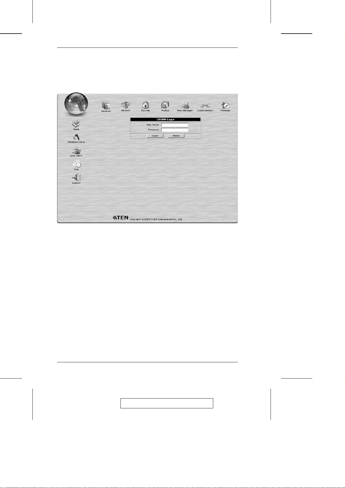
3. Accept the certificate. If a second certificate appears, accep t it as well.
The CN-5000 login page appears:
4. Provide a valid Username and Password (set by the CN-5000
administrator), then Click Login to continue.
Note: 1. If you are the administrator, and are logging in for the first time,
use the default Username: administrator; and the default
Password: password. For security purposes, we strongly
recommend you remove these and give yourself a unique
Username and Password (see User Manager, p. 24).
2. If you supplied an invalid login, the authentication routine will
return this message: Invalid Username or Password. Please try
again. If you see this message, log in again being careful with
the Username and Password.
12
2005-09-13
Page 25

3. Getting Started
After you have successfully logged in, the CN-5000 Main Page appears:
2005-09-13
13
Page 26

CN-5000 User Manual
Screen Elements
The icons arranged horizontally across the top of the page are linked to the
administration utilities, which are used to configure the CN-5000. Your
ability to make configuration changes depends on the permissions associated
with your login information (see User Management, p. 24). Use of the
administrative functions is discussed in Chapter 4.
The icons arranged vertically down the left side of the page are used to
operate the CN-5000. Their purpose is discussed in the table below:
Icon Purpose
Saves the changes you make in the administration dialog boxes
(see the Administration chapter), but does not implement the
changes. The changes only go into effect when you enable
Reset on exit (see p. 26 for details) and log out.
Allows users with the proper permission (see p. 25), to connect
to the CN-5000 using Windows software, and to remotely
control the connected server (or servers via a KVM switch).
14
For platform independence, the Java client allows users with the
proper permission (see p. 25), that have Java installed to
connect to the CN-5000 and to remotely control the connected
server (or servers via a KVM switch).
If a Power over the NET™ module is connected to your
installation, and if you have the proper permission (see p. 25),
clicking this icon will bring up its interface.
All the events that take place on the CN-5000 are recorded in a
log file. If you have the proper permission (see p. 25), clicking
this icon displays the contents of the log file.
Click this icon to log out and end your CN-5000 session.
Note: It is important to log out when you end your session.
Otherwise, you must wait until the timeout setting has expired
before the CN-5000 can be accessed again. (See Time out
control under the Customization dialog box, p. 26.)
2005-09-13
Page 27

Chapter 4.
Administration
Introduction
The administration utilities, represented by the icons located across the top of
the CN-5000 web page, are used to configure the CN-5000 for operation.
This chapter discusses each of them in turn. As you make your configuration
changes, Click the Apply icon at the upper left of the web page to save the
changes in the CN-5000’s configuration file. To have the changes actually take
effect, you have to put a check in the Reset on Exit box (see Customization, p.
26), and log out.
Note: If you don’t have Configuration privileges (see User Management, p.
24) the Administration configuration dialogs are available for
viewing, but the input fields are disabled, and cannot be changed.
2005-09-13
15
Page 28

CN-5000 User Manual
General
Once you login, the General panel displays on the web page:
It is the first of the Administration pages, and provides information about the
CN-5000’s status.
An explanation of each of the fields is given in the table below:
Device Name: To make it easier to manage installations that have
MAC Address: The CN-5000’s MAC Address displays here.
Firmware Version: Indicates the CN-5000’s current firmware version level.
more than one CN-5000, each one can be given a
name. To assign a name for the CN-5000, key in one
of your choosing here (15 characters max.).
Note: New versions of the CN-5000’s firmware can be downloaded from
our website as they become available, (see p. 27 for details).
16
2005-09-13
Page 29
4. Administration
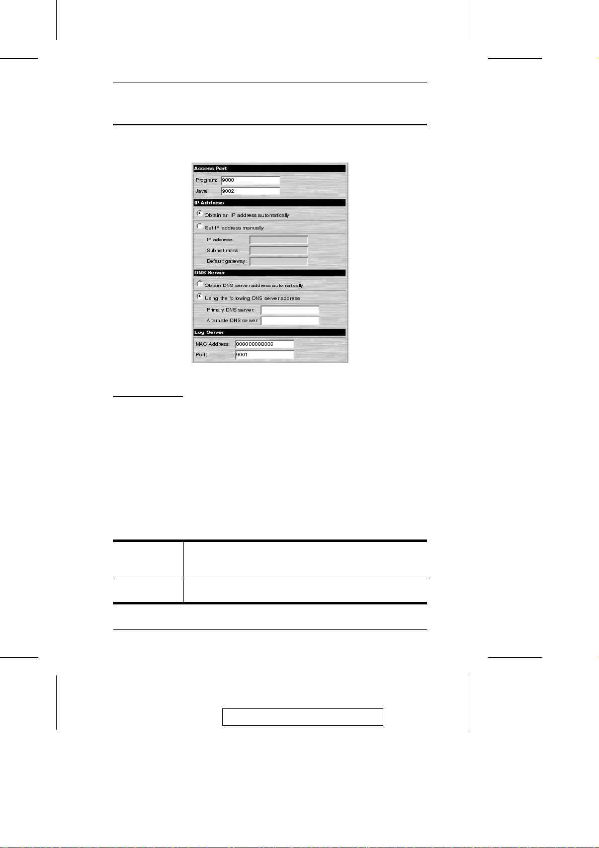
Network
The Network dialog is used to specify the CN-5000’s network environment.
Access Port
As a security measure, if a firewall is being used, the Administrator can
specify the port numbers that the firewall will allow (and set the firewall
accordingly). Users must specify the port number as par t of th e IP ad dres s
when they log in to the CN-5000. If an invalid port number (or no port
number) is specified, the CN-5000 will not be found.
Note: If there is no firewall (on an Intranet, for example), it doesn’t matter
what these numbers are set to, since they have no effect.
An explanation of the fields is given in the table below:
Program: This is the port number that must be specified when connecting
from the Administrator and Windows Client software programs.
Valid entries are from 1024 - 60,000.
Java: This is the port number used for Java Client connections. Valid
entries are from 0 - 65535.
17
2005-09-13
Page 30

CN-5000 User Manual
IP Address
The CN-5000 can either have its IP address assigned dynamically at bootup
(DHCP), or it can be given a fixed IP address.
w For dynamic IP address assignment, select the Obtain an IP address
automatically, radio button.
Note: If the CN-5000 is on a network that uses DHCP to assign network
addresses, and you need to ascertain its IP address, see IP Address
Determination, p. 88, for information.
w To specify a fixed IP address, select the Set IP address manually, radio
button and fill in the IP address.
DNS Server
The CN-5000 can either have its DNS server address assigned automatically,
or a fixed address can be specified.
w For automatic address assignment, select the Obtain DNS server address
automatically, radio button.
w To specify a fixed address, select the Use the following DNS server
address, radio button and fill in the required information.
Log Server
Important transactions that occur on the CN-5000, such as logins and internal
status messages, are kept in an automatically generated lo g file.
Specify the MAC address and a Port number for the server you want the log
server software to reside on.
18
2005-09-13
Page 31

Security
The Security page is used to control access to the CN-5000.
4. Administration
w IP and MAC Filters permit or deny access to the CN-5000 for specific IP and
MAC addresses attempting to access the system.
w As a security feature, the Default Java program name lets the
Administrator specify an addition to the IP address that users must
include when they log into the CN5000 from their browsers, and when
they access the CN-5000 with the Java Client. For example:
192.168.0.126/abcdefg
Note: 1. If no page is specified here, no one will be able to access the
CN-5000 with the Java Client.
2. For security purposes, we recommend that you change the name
of this page from time to time.
w Admin station filters are not supported in the browser version of the
Administrator Utility. They are only supported in the AP version. See p.
58 for a discussion of filtering using the AP program.
19
2005-09-13
Page 32

CN-5000 User Manual
Filtering
There are a maximum of 100 filters allowed for each category: User IPs;
User MACs; and Administrator MACs. User Station filtered items (IPs and
MACs) can be specified as included or excluded by hig hlig h tin g th e item an d
clicking the include or exclude radio button.
w If the include button is checked, all the addresses within the filter range
are allowed access to the CN-5000; all other addresses are denied access.
w If the exclude button is checked, all the addresses within the filter range
are denied access to the CN-5000; all other addresses are allowed access.
User Station Filtering - IPs:
To enable IP filtering for User Stations, Click to put a check mark in the IP
Filter enable checkbox.
To add a filter:
1. Select whether to include or exclude the filter.
2. Click Add. A dialog box similar to the one below appears:
3. Specify the filter address in the dialog box, then Click OK.
Each IP filter can consist of a single address, or a range of addresses.
Therefore, a second dialog box similar to the one below appears:
20
2005-09-13
Page 33

4. Administration
4. To filter a single IP address, key in the same address as the start IP. To
filter a continuous range of addresses, key in the end number of the range.
After filling in the address, click OK.
5. Repeat these steps for any additional IP addresses you want to filter.
To delete a filter, select it and Click Remove. To modify a filter, select it and
Click Edit. The Edit dialog box is similar to the Add dialog box. When it comes
up, simply delete the old address and replace it with the new one.
User Station Filtering - MACs:
To enable MAC filtering for User Stations, Click to put a check mark in the
MAC Filter enable checkbox.
To add a filter:
1. Select whether to include or exclude the filter.
2. Click Add. A dialog box similar to the one below appears:
3. Specify the filter address in the dialog box, then Click OK.
4. Repeat these steps for any additional MAC addresses you want to filter.
To delete a filter, select it and Click Remove. To modify a filter, select it and
Click Edit. The Edit dialog box is similar to the Add dialog box. When it comes
up, simply delete the old address and replace it with the new one.
21
2005-09-13
Page 34

CN-5000 User Manual
Radius
If you are using a RADIUS server, RADIUS Configuration allows you to set
up its parameters:
1. Check Enable RADIUS.
2. Fill in the IP addresses and Service Ports for the Primary and Alternate
RADIUS servers.
3. Set the time in seconds that the CN-5000 waits for a RADIUS server
reply before it times out in the Timeout field.
4. Set the number of RADIUS retries allowed in the Retries field.
5. Key the Shared Secret character string that you want to use for
authentication between the CN-5000 and the RADIUS Server in this field.
22
2005-09-13
Page 35

4. Administration
6. On the RADIUS server, set the access rights for each user acco rdin g to
the information in the table, below:
Character Meaning
C
W
J
P
L
Grants the user administrator privileges, allowing the user to
configure the system.
Allows the user to access the system via the Windows Client
program.
Allows the user to access the system via the Java Client program.
Allows the user to access an attached PN0108 device.
Allows the user to access log information via the user’s browser.
Note: 1. The characters are not case sensitive. Capitals or lower case
work equally well.
2. Characters are comma delimited.
3. An invalid character in the in the configuration string will
prohibit access to the CN-5000 for the user.
Examples:
String Meaning
c,w,p
w,j,l
User has administrator priveleges; user can access the system via
the Windows Client; user can access the attached PN0108
User can access the system via the Windows Client; user can
access the system via the Java Client; user can access log
information via the user’s browser.
23
2005-09-13
Page 36

CN-5000 User Manual
User Manager
This configuration dialog is used to manage user profiles.
w A maximum of 64 user profiles can be created.
w To add a user, fill in the information asked for in the User Info dialog box
and Click Add.
w To delete a user profile, select it from the list in the upper panel, and
Click Remove.
w To modify a user profile, select it from the list in the upper panel; change
the information shown in the User Info dialog box; and Click Update.
w The Reset button clears all the information shown in the User Info dialog
box fields.
24
2005-09-13
Page 37

4. Administration
An explanation of the profile items is given in the table below:
Username A minimum of 6 and a maximum of 15 characters is allowed.
Password A minimum of 8 and a maximum of 15 characters is allowed.
Confirm Password To be sure there is no mistake in the password you are asked
Description Additional information about the user that you may wish to
Permissions Click to place/remove a check mark next to an item to
to enter it again. The two entries must match.
include.
grant/withhold access to that aspect of the CN-5000’s
operation that the time governs
Configure: Checking Configure gives a User Administrator
priveleges, and allows the user to set up and modify the
CN-5000’s operating environment.
Windows Client: Checking Windows client allows a User to
access the CN-5000 via the Windows Client software.
Java Client: Checking Java client allows a User to access the
CN-5000 via the Java Client software.
Log: Checking Log allows a User to view the contents of the
log file.
Power Management: Checking Power Management allows a
User to access and operate an attached Power over the Net™
module.
2005-09-13
25
Page 38

CN-5000 User Manual
Customization
This configuration dialog allows the Administrator to set Timeout, Login failure,
and Working mode parameters.
An explanation of the Customization parameters is given in the table below:
Time out Control If the CN-5000 doesn’t receive any input from a computer that is
Login failure Login failures allowed, sets the number of consecutive failed
Working Mode If Stealth Mode is enabled, the CN-5000 cannot be pinged. If
Multiuser
Operation
Reset on exit Placing a check here causes the CN-5000 to reset itself and
26
accessing it with the Windows or Java client for the amount of
time specified here, it ends the connection.
login attempts that are permitted from a remote computer.
Login failure timeout, sets the amount of time a remote
computer must wait before attempting to login again after it
has exceeded the number of allowed failures.
Echo Mode is disabled, the CN-5000 will not show up in the list
of local CN-5000 units when accessing it with the AP program.
See p. for details.
Enabling Multiuser operation permits more than one user to
log into the CN-5000 at the same time.
implement all the new changes when you log out. A wait of
approximately 30 to 60 seconds is necessary before logging in
following the reset.
2005-09-13
Page 39

4. Administration
Firmware
New versions of the CN-5000 firmware can be downloaded from our website:
www.aten.com.tw
as they become available. To upgrade the firmware, do the following:
1. After downloading the new firmware file to your computer, click the
Firmware icon to open the Firmware configuration dialog:
2. Click the Browse button; navigate to the directory that the new fir m war e
file was downloaded to, and select it.
3. Click Upload.
4. After the upload completes, click the Apply icon at the left of the web
page.
5. Enable the Reset on exit checkbox (see Customization, p. 26).
6. Click the Apply icon at the left of the web page, again.
7. Click the Logout icon at the upper right of the web page (see p. 12) to
exit and reset the CN-5000.
27
2005-09-13
Page 40

CN-5000 User Manual
Notes:
28
2005-09-13
Page 41

Chapter 5.
The Windows Client
Starting Up
To access the CN-5000 with the Windows Client software:
1. After you log in, Click the Windows Client icon at the left of the web page
(see p. 12).
Note: You must have DirectX 7.0 or higher installed on your computer.
If not, the Client program will not load.
2. In the File Download dialog box that comes up, click Open to run the program.
Note: 1. If the browser cannot run the program, save it to disk, instead.
Then, with your browser still open to the CN-5000 web page,
run the file from your disk.
2. If you use the save to disk method, for security purposes, you
cannot simply run a previously downloaded version of the
program. Each time you want to access the CN-5000, you must
log in to the web page with a valid username and password to
download a fresh copy of the program.
3. When a connection to the CN-5000 has been established, a screen similar
to the one below appears:
2005-09-13
29
Page 42

CN-5000 User Manual
Note: 1. If Full Screen Mode is enabled (there is a checkmark in the
box), the remote display fills the entire screen of your local
monitor.
2. If Full Screen Mode is not enabled (there is no checkmark in the
box), the remote display appears as a window on your desktop.
If the remote screen is larger than what is able to fit in th e
window, move the mouse pointer to the screen border that is
closest to the area you want to view and the screen will scroll.
Clicking the push pin icon in the title bar will cause the window
to remain on top of all other open windows on your desktop.
3. If Keep Screen Size is enabled (there is a checkmark in the box),
the remote screen is not resized.
w If the remote resolution is smaller, its display appears
as a window centered on your screen.
w If the remote resolution is larger, its display is centered
on your screen. To access the areas that are off screen,
move the mouse to the corner of the screen that is
closest to the area you want to view and the screen will
scroll.
4. If Keep Screen Size is not enabled (there is no checkmark in the
box), the remote screen is resized to fit the resolution of your
local monitor.
4. Click Switch to take over console control of the unit that the CN-5000 is
connected to.
30
2005-09-13
Page 43

5. The Windows Client
Operation
Once the Switch to the CN-5000 has been accomplished, the remote system’s
video output is captured and displayed on your monitor. At the same time, your
local keystroke and mouse input is captured and sent to the remote system.
OSD Control Panel
A small OSD control panel opens at the lower right hand corner of the screen:
The panel consists of an icon bar with two text bars below it. Initially, the
text bars display the video resolution and IP address of th e remo te dev ice. As
the mouse moves over the icons, the text bars describe the icon’s function.
The functions that the icons perform is described in the table below.
Icon Function
Click and drag the hand to move the OSD display to another
position on the screen.
Click to bring up the Hotkey Setup dialog box (see p. 34 for details).
Click to bring up the Video Adjustment dialog box. Right click to do
a fast Auto Sync (see p. 36 for details).
Click to exit the Windows Client control of the remote unit.
(Space)
Hover over the space to see the video resolution and IP address of
the device at the remote location.
These LEDs show the Num Lock, Caps Lock, and Scroll Lock status
of the remote computer. Click on the icon to toggle the status.
Note: When you first connect, the LED display may not be
accurate. To be sure, click on the LEDs to set them.
31
2005-09-13
Page 44

CN-5000 User Manual
Keystrokes
Except for [Alt + Tab] and [Ctrl + Alt + Del], the effect of all keyboard
input takes place on the remote computer . The above two combinations ar e
retained on the local system to switch among applications and to recover
from disaster. In order to provide the [Alt + Tab] and [Ctrl + Alt + Del]
functions on the remote system, a Function key (F1 - F12) can be selected as
a substitute for the [Alt] key.
For example, if you choose [ F12] as the substitute, then [F12 + Tab] would
switch among applications on the remote system, and [Ctrl + F12 + Del],
would be the disaster recovery combination. See Configuring the Hotkeys on
p. 36 for details on setting up a substitute key.
Note: While any Function Key can be used for the Substitute key, you must
not use one that is being used for another action.
Mouse Synchronization
Until you close the CN-5000 connection, mouse movements have no effect
on your local system, but are captured and sent to the remote system, instead.
From time to time, especially if you change video resolution, the local mouse
movement may no longer be synchronized with the remote system’s mous e
pointer. There are three quick methods that can be used to bring th e tw o
pointers back into sync: 1) Moving the mouse pointer over the Arrow in the
OSD panel and right clicking; 2) Moving the mouse pointer into the OSD
panel and then moving it back out again; and 3) Performing an Auto Sync
with the Video Adjustment function (see Video Adjustment, p. 36 for details).
If performing these actions doesn’t resolve the problem, do the following:
1. Invoke the Adjust Mouse action with the Adjust Mouse hotkeys (see p. 35
for details).
2. Move the local mouse pointer exactly on top of the remote mouse pointer
and Click.
If these procedures still do not help, set the mouse speed and acceleration for the
computer (or computers via KVM switch) connected to the CN-5000 as follows:
32
2005-09-13
Page 45

5. The Windows Client
Windows 2000:
Set the mouse speed to the middle position; set the mouse acceleration to
None (Control Panel → Mouse → Mouse Properties → Motion):
Windows XP/Server 2003:
Set the mouse speed to the middle position; disable Enhance Pointer
Precision (Control Panel → Printers and Other Hardware → Mouse →
Pointer Options):
33
2005-09-13
Page 46

CN-5000 User Manual
WinMe:
Set the mouse speed to the 5th position; disable mouse acceleration (click
Advanced to get the dialog box for this).
WinNT / Win98 / Win95:
Set the mouse speed to the slowest position.
Sun / Linux:
Open a terminal session and issue the following command:
xset m 1
Sun:
Linux: xset m 0
Hotkeys
The Hotkey Setup Screen:
Various configuration actions related to the keyboard, video, and mouse can
be performed via hotkey combinations. The Hotkey setup utility is accessed
by clicking the Keyboard icon on the OSD Control Panel. The actions
performed by the Hotkeys are listed in the lef t co lu m n ; th e cu rren tly def in ed
keys that invoke the actions are shown in the column to the right.
34
2005-09-13
Page 47

5. The Windows Client
An explanation of the actions is given in the table, below:
Action Explanation
Exit remote location Break the connection to the CN-5000 and return to local
Adjust Video Bring up the video adjustment utility.
Toggle OSD Toggles the OSD display Off and On.
Toggle mouse display If you find the display of the two mouse pointers (local and
Adjust mouse This utility synchronizes the local and remote mouse
Substitute Alt key Although all other keyboard input is captured and sent to
operation.
remote) to be confusing or annoying, you can use this
function to shrink the non-functioning pointer down to a
barely-noticeable tiny circle - which can be ignored. Since
this function is a toggle - use the hotkeys again to bring the
mouse display back to its original configuration.
movements following a video resolution change. After
invoking this utility, simply click the local mouse pointer on
top of the remote mouse pointer.
the CN-5000, [Alt + Tab] and [Ctrl + Alt + Del] work on your
local computer. In order to implement their effects on the
remote system, a function key is be substituted for the Alt
key. If you substitute the F12 key, for example, you would
use [F12 + Tab] and [Ctrl + F12 + Del].
Note: To invoke an action, you must press and release the keys one key at a
time - do not chord the keys.
35
2005-09-13
Page 48

CN-5000 User Manual
Configuring the Hotkeys:
If you find the default Hotkey combinations inconvenient, you can configure
them to whatever suits your taste, as follows:
1. Highlight the Action, then Click Start
2. Key in the Function keys (one at a time). The key names appear in the
Key field as you press them.
3. When you have finished keying in your sequence, Click Stop
4. Click Set
5. Repeat for any other actions you wish to set up
Note: You can use the same function keys for more than one action, as long
as the first key is not the same. For example, you can use F1 F2 F3
for one action; F2 F1 F3 for another; F3 F2 F1 for a third, etc.
Video Adjustment
You can adjust the placement and the picture quality of the remote screen (as
displayed on your local monitor) with the Video Options function. To do so,
either click on the Hammer icon on the OSD Control Panel, or use the Adjust
Video hotkeys (see p. 35). The following screen appears:
36
2005-09-13
Page 49

5. The Windows Client
The meanings of the adjustment optio ns ar e giv en in th e tab le belo w:
Option Usage
Screen Position Adjust the horizontal and vertical position of the remote
Auto-Sync Click Auto-Sync to have the function detect the vertical and
RGB Drag the slider bars to adjust the RGB (Red, Green, Blue)
Video Quality Drag the slider bar to adjust the overall Video Quality. Values
Sense If you need to adjust the gamma level of the remote video
computer window by Clicking the Arrow buttons.
horizontal offset values of the remote screen and automatically
synchronize it with the local screen.
If the local and remote mouse pointers are out of sync, in most
cases, performing this function will bring them back into sync.
Note: This function works best with a bright screen.
If you are not satisfied with the results, use the Screen Position
arrows to position the remote display manually.
values. When an RGB value is increased, the RGB component
of the image is correspondingly increased.
can be from 20 to 100. The larger the value, the clearer the
picture and the more video data goes through the network.
Depending on the network bandwidth, a high value may
adversely effect response time.
display, put a check mark in the Enable box, then drag the
slider bar until the desired result is obtained.
2005-09-13
37
Page 50

CN-5000 User Manual
Notes:
38
2005-09-13
Page 51

Chapter 6.
The Java Client
Introduction
The Java Client makes the CN-5000 accessible to all platforms that have
Java 2 installed. Java 2 is available for free download from Sun’s Java web
site (http://java.sun.com). To access the CN-5000 with the Java Client
software:
1. After you log in (see p. 12), Click the Java Client icon.
Note: When you log in, be sure to specify the Java Program Name when
you specify the CN-5000’s IP address. For example:
192.168.0.125/abcdefg
Otherwise you will not be granted access. If you don’t know the
program name, get it from your Administrator.
2. In the dialog box that appears, select Open.
Note: If the browser won’t open the Java Client program, save the
program to disk and, with your browser still open, Launch it after
the save.
After a second or two, an Authentication progress window appears:
39
2005-09-13
Page 52

CN-5000 User Manual
Once the authentication procedure completes successfully, the remote
system displays on your monitor:
40
2005-09-13
Page 53

6. The Java Client
Operation
You can work on the remote system via the screen display on your monitor
just as if it were your local system.
Note: 1. You can switch between your local and remote programs with
[Alt + Tab].
2. Due to net lag, there might be a slight delay before your
keystrokes show up. You may also have to wait a bit for the
remote mouse to catch up to your local mouse before you click.
3. Due to net lag, or insufficient computing power on the local
machine, some images, especially motion images, may display
poorly.
4. If the local and remote mouse pointers get out of sync, you can
use the Mouse Synchronization Button to bring them back into
synch (see p. 43 for details).
The Toolbar
The Java Client’s toolbar gives you control over the KVM operations. It is
hidden in the blank area at the bottom center of th e s cr een , an d ap pears when
you move the mouse pointer over this area.
Going from left to right, the toolbar functions are explained in the sections
that follow.
41
2005-09-13
Page 54

CN-5000 User Manual
Video:
Clicking the first button brings up the Video Settings dialog box:
This is similar to the Adjust Video feature of the Windows Client. See p. 36
for details about its use.
Note: We recommend that you perform an Autosync right after you connect
for improved mouse synchronization.
Keypad:
Clicking the second button, brings up the Keypad.
Since some locally input keyboard combinations can
not be captured and sent to the CN-5000, the Keypad
provides a one-click implementation of their actions
on the remote system.
42
2005-09-13
Page 55

6. The Java Client
Mouse:
At times the local mouse movement may lose sync with the remote mouse
movement. You can try getting them back in sync with a fast mouse
synchronization by moving the mouse pointer down into the Java Client toolbar.
If that doesn’t help, do an Autosync (as discussed on the previous page).
If an Autosync doesn’t resolve the problem the Mouse Synchronization
function can get them back into sync. This is similar to the Mouse
Synchronization feature of the Windows Client (see p. 32 for details).
1. Click the Mouse Synchronization button.
The remote mouse pointer moves to the upper left area of the screen.
2. Move your local mouse pointer directly over the remote mouse pointer and Click.
Lock LEDs:
These LEDs show the Num Lock, Caps Lock, and Scroll Lock status of the
remote computer. Click on the icon to toggle the status.
Note: When you first connect, the LED display may not be accurate. To be
sure, click on the LEDs to set them.
Screen Mode:
Clicking this button toggles the display between full screen and windowed
modes.
? Button:
The
Clicking this button brings up the Java Client Help pages.
Exit:
Click this button to exit the Java Client program and return to local operation.
43
2005-09-13
Page 56

CN-5000 User Manual
Notes:
44
2005-09-13
Page 57

Chapter 7.
The Log File
The Log File Screen
The CN-5000 logs all the events that take place on it. Following a reset, it
writes them to a log file, which is a searchable database. To view the contents
of the log file, click the Log icon at the lower left of the page. A screen
similar to the one below appears:
2005-09-13
45
Page 58

CN-5000 User Manual
A maximum of 512 events are kept in the log file. As new events are
recorded, they are placed at the bottom of the list. When a new ev en t is
recorded after there are 512 events in the log file, the earliest event in the list
is discarded.
Note: To maintain and view a record of all the events that take place (not
just the most recent 512), set up the Log Server AP program. See p.
77 for details.
To clear the log file, click on the Clear Log icon at the lower right of the
page.
46
2005-09-13
Page 59

Chapter 8.
AP Operation
In addition to the browser based operation utilities, the CN-5000 also
provides Windows-based programs that can be used in their s tead . Th es e
include an administration utility, a Windows client, a Java client, and a Log
Server. This chapter explains how to install and operate each of th em .
The Administrator Utility
Installation
The Windows-based Administrator Utility is provided on the distribution CD
included with this package. To install the Administrator Utility:
1. Open the drive and folder where the Administrator Setu p ico n
(CN5KAdminTool.exe) is located and double click the icon.
The Administration Utility installation screen appears:
2. Click Next and follow the on-screen instructions. When the installation
completes, a CN5000AdminTool icon appears on your desktop.
2005-09-13
47
Page 60

CN-5000 User Manual
Starting Up
To bring up the Administrator Utility Main Screen, double click the
CN5KAdminTool icon, or key in the full path to the program on the
command line.
If this is the first time that you are running the utility a dialog box appears
requesting you to input your serial number. The serial number can be found
on the CN-5000’s CD case. Key in the serial number - 5 characters per box then Click OK.
The Administrator Utility searches for CN-5000 devices installed on the local
LAN segment. When it has finished, it displays the CN-5000 devices it found in
a window similar to the one below:
w If the unit you wish to configure appears in the CN-5000 devices listbox,
Double Click it.
w If the unit you want doesn’t appear in the listbox, key in its IP address in
the CN-5000 address field, and its Port number in the Port box, then
Click Login.
48
2005-09-13
Page 61

8. AP Operation
Note: 1. The Port number that corresponds to a unit’s IP address is set by
the Administrator on the Network configuration page (see p. 55
for details).
2. Clicking the Refresh button causes the utility to rescan th e lo cal
LAN segment for CN-5000 devices.
3. If the utility fails to connect to a unit that you specified, it assigns
another free IP address (if one exists), to that device and attempts
to connect again.
4. When the Administrator Utility searches for CN-5000 devices, if
it finds a unit that was originally on a different network segment
that still has a fixed IP address from its previous location, it will
list the unit (showing the IP address), but you cannot connect to it.
You should change the unit’s IP address to match its current
network segment (see IP Address Determination, p. 88, for
details).
2005-09-13
49
Page 62

CN-5000 User Manual
Logging In
Once the Administrator Utility connects to the unit you specified, a login
window appears:
Only those who have Configuration privileges (see User Management;
Permissions, p. 60) are allowed to log in.
Provide a valid Username and Password, then Click Login to continue.
Note: The default Username is administrator; the default Password is
password. You can change these to whatever you prefer (see User
Management, p. 60) after you have logged in.
While the Utility processes the login request, the following message appears:
Note: If you supplied an invalid login, the authentication routine will return
a message informing you that the “server is busy.” This is done as a
security measure to confuse and discourage hackers from trying to
discover a valid Username and Password. If you see this message, try
logging in again being careful with the Username and Password
50
2005-09-13
Page 63

8. AP Operation
If you successfully log in to the CN-5000 with the default username and
password, the following message appears:
For security purposes, be sure to change the default Username and Password
to something unique (see User Management, p. 60).
2005-09-13
51
Page 64

CN-5000 User Manual
The Settings Notebook
After successfully logging in, the Settings notebook appears.
There are five tabs, each representin g a dif fer en t ad m in is tr ativ e functio n. A
description of the functions how to configure their settings is provided in the
sections that follow.
52
2005-09-13
Page 65

8. AP Operation
Uploading Changes
When the Settings have been configured to your satisfaction and you are
ready to upload the changes to the CN-5000:
1. If you made changes on the Network page, or if you upgraded the
firmware on the Customization page, you must enable Reset on Exit (see
p. 62) before going to step 2.
2. Click OK (at the bottom of the Settings notebook), to start the updating
procedure.When updating has finished, the following message displays:
3. Click OK and you return to the Administration Utility device selection
window (see p.26 ).
Note: To abandon the changes you made and return the settings to the
values they had before you ran the Utility, Click Cancel.(at the
bottom of the Settings notebook) instead of OK in step 1.
2005-09-13
53
Page 66

CN-5000 User Manual
General:
The General page provides information about the CN-5000’s status.
An explanation of each of the items is given in the table below:
MAC Address The CN-5000’s MAC Address displays here.
Device Name: To make it easier to manage installations that have
Main Firmware Version: Indicates the mainboard’s current firmware version
more than one CN-5000, each one can be given a
name. To assign a name for the CN-5000, erase the
current name and key in one of your choosing (15
characters max.).
level.
New versions of the CN-5000’s firmware can be downloaded from our web
site as they become available (see p. 64 for upgrading details).
54
2005-09-13
Page 67

Network:
This page is used to specify the CN-5000’s network environment.
8. AP Operation
The Network page is divided into three main sections: Access Ports, IP
Address, and Log Server. Each section is discussed below.
Access Ports:
As a security measure, the Administrator can s et th e P ort num ber s th at th e
User must specify when he attempts to connect to a CN-5000’s IP address.
Unless the correct Port number is given, the CN-5000 device will not be
found. An explanation of the fields is given in the table below:
Program: This is the port number that must be specified when connecting
from the Administrator and Windows Client software programs.
Valid entries are from 1024 - 60,000.
Java: This is the port number used for Java Client connections. Valid
entries are from 0 - 65535.
55
2005-09-13
Page 68

CN-5000 User Manual
IP Address:
w The CN-5000 can either have its IP address assigned dynamically at
bootup (DHCP), or it can be given a fixed IP address.
§ For dynamic IP address assignment, select the Obtain an IP address
automatically, radio button.
§ T o specify a fixed IP address, select the Set IP address manually,
radio button and fill in the required information.
Note: A fixed IP address can also be assigned with the ARP
command as follows:
arp -s <ip address> <CN-5000’s MAC address>
For example,
arp -s 10.0.0.10 00-48-54-65-00-01
assigns an IP address of 10.0.0.10 to a CN5000 with a MAC
address of 00-48-54-65-00-01.
w The CN-5000 can either have its DNS address assigned automatically, or
a fixed address can be specified.
§ For automatic address assignment, select the Obta in DNS s er ver
address automatically, radio button.
§ T o specify a fixed address, select the Us e th e fo llo win g DNS s er ver
address, radio button and fill in the required information.
Log Server:
Important transactions that occur on the CN-5000, such as logins and internal
status messages, are kept in an automatically generated lo g file. Specif y th e
MAC address and a Port number for the server you want the log file to reside
on in the Log Server section. The Log Server is discussed in detail on p 77.
Note: The Log Server port number must be different from the port numbers
that were specified for Program and Java in the Access Ports section.
56
2005-09-13
Page 69

Security
The Security page is used to control access to the CN-5000.
8. AP Operation
w User station filters permit or deny access to the CN-5000 for specific IP
and MAC addresses attempting to access the system.
w The Default Java program name lets the Administrator specify an
addition to the IP address that the user must include when he accesses the
CN-5000 with the Java Client. For example:
192.168.0.126/abcdefg
Users must include this name in the IP address, or they will not be
granted access.
Note: 1. If no page is specified here, no one will be able to access the
CN-5000 with the Java Client.
2. For security purposes, we recommend that you change the name
of this page from time to time.
w Admin station filters specify which MAC addresses are allowed to access
the system with the CN-5000 Administrator program. If nothing is
specified here, there are no restrictions.
57
2005-09-13
Page 70

CN-5000 User Manual
Filtering
w There are a maximum of 100 filters allowed for each category (User IPs,
User MACs, and Administrator MACs).
w To enable filtering for User Stations, Click to put a check mark in the IP
and/or MAC Filter enable checkbox.
w To add a filter, Click Add. A dialog box similar to the ones below appears
(the top example is for IP address filters; the bottom is for MAC address
filters):
§ Specify the filter address in the dialog box, then Click OK.
§ Each filter can consist of a single IP or MAC address, or a range of IP
addresses. For a single IP address filter, the address is the same for
both the From and To fields.
w To delete a filter, select it and Click Remove; To modify a filter, select it
and Click Edit. The Edit dialog box is similar to the Add dialog box.
When it comes up, simply delete the old address and replace it with the
new one.
58
2005-09-13
Page 71

8. AP Operation
w User Station filtered items can be specified as included or excluded by
highlighting the item and clicking the include or exclude radio button.
§ If the include button is checked, all the addresses within the filter
range are allowed access to the CN-5000; all other addresses are
denied access.
§ If the exclude button is checked, all the addresses within the filter
range are denied access to the CN-5000; all other addresses are
allowed access.
w The Administrator station filter dialog boxes are similar to the MAC filter
dialog boxes for user stations.
An example of the Security page with filters configured is shown below:
2005-09-13
59
Page 72

CN-5000 User Manual
User Management
This page is used to set up and manage user profiles. It defines the access
rights of each user. Up to 64 user profiles can be established.
w A maximum of 64 users can have access to a CN-5000.
w To add a user, Click Add and fill in the information asked for in the User
Management dialog box that appears. (See p. 60.)
w To delete a user profile, select it and Click Remove.
w To modify a user profile, select it; Click Edit; and change the information
shown in the User Management dialog box that appears.
60
2005-09-13
Page 73

8. AP Operation
When you click Add or Edit, the following dialog box appears:
An explanation of the profile items is given in the table below:
Username A minimum of 6 and a maximum of 15 characters is allowed.
Password A minimum of 8 and a maximum of 15 characters is allowed.
Confirm Password To be sure there is no mistake in the password you are asked
Description Additional information about the user that you may wish to include.
Permissions Click to place/remove a check mark next to an item to
to enter it again. The two entries must match.
grant/withhold access to that aspect of the CN-5000’s
operation that the time governs
Configure: Checking Configure gives a User Administrator
privileges, and allows the user to set up and modify the
CN-5000’s operating environment.
Windows Client: Checking Windows client allows a User to
access the CN-5000 via the Windows Client software.
Java Client: Checking Java client allows a User to access the
CN-5000 via the Java Client software.
Power Management: Checking Power Management allows a User
to access and operate an attached Power over the Net™ module.
Log: Checking Log allows a User to view the contents of the
log file.
View Only: Checking View Only allows the User to view the
video display of the computers attached to the ports of the
KVM switch connected to the CN-5000, but they are not
allowed to perform any operations on the computers.
2005-09-13
61
Page 74

CN-5000 User Manual
Customization
This page allows the Administrator to upgrade the firmware and to set
Timeout and Login failure parameters.
62
2005-09-13
Page 75

8. AP Operation
An explanation of the Customization items is given in the table below:
Uploads After obtaining a new version of the firmware, click Browse
Time out control If the CN-5000 doesn’t receive any input from a logged in user
Login failure
Working mode
Multiuser operation Placing a check here allows multiple users to access the
Reset on exit Placing a check here causes the CN-5000 to reset itself
to navigate to the directory that you have put it in.
for the amount of time specified here, it ends the connection.
Login failures allowed, sets the number of consecutive
w
failed login attempts that are permitted from a remote
computer.
Login failure timeout, sets the amount of time a remote
w
computer must wait before attempting to login again after
it has exceeded the number of allowed failures.
If Stealth Mode is enabled, the CN-5000 cannot be
w
pinged.
w If Echo Mode is disabled, the CN-5000 will not show up
in the list of local CN-5000 units (see p. 48 and p. 67).
w If Enable Browser isn’t enabled, the CN-5000 cannot be
accessed via a browser.
CN-5000 at the same time. Up to 16 users can log in at the
same time this way.
and implement all the new changes when you Click OK.
2005-12-29
63
Page 76

CN-5000 User Manual
Upgrading the Firmware
New versions of the Mainboard firmware files can be downloaded from our
website as they become available. After downloading the new firmware file,
to upgrade the firmware, do the following:
1. Go to the Customization page of the Administration configuration
notebook (see p. 62) and Click the Browse button for the component you
want to upgrade.
2. In the File Open dialog box that appears, navigate to the directory that the
downloaded firmware upgrade file is in, and select the upgrade file.
64
2005-09-13
Page 77

8. AP Operation
3. Click Open.
You return to the Customization page with the path to the file, and the
Upload version number displayed.
Note: If you select the wrong file type for the component you are
upgrading an Invalid file type message appears when you click
Open. Go back and select the correct file type.
4. Enable the Reset on exit checkbox.
5. Click OK to save your settings and reset the CN-5000. Following the
reset, wait approximately 30 to 60 seconds before logging back in to the
Administrator Utility.
65
2005-09-13
Page 78

CN-5000 User Manual
The Windows Client
The Windows-based Client software is provided on the distribution CD
included with this package.
Installation
To install the Windows Client:
1. Open the drive and folder where the Windows Client Setup icon
(CN5KClient.exe) is located and double click the icon.
The Windows Client installation screen appears:
2. Click Next and follow the on-screen instructions. When the installation
completes, a CN5000 Client icon appears on your desktop.
66
2005-09-13
Page 79

8. AP Operation
Starting Up
To bring up the Windows Client Main Screen, Double Click the CN5K
Client icon, or key in the full path to the program on the command line.
If this is the first time that you are running the program, a dialog box appears
requesting you to input your serial number:
If you don’t know what it is, contact the CN-5000 administrator. Key in the
serial number - 5 characters per box - then Click OK.
Note: You must have DirectX 7.0 or higher installed on your computer. If
not, the Client program will not load.
The Connection Screen
When the Windows Client starts, a Connection Screen, similar to the one
below, appears:
67
2005-09-13
Page 80

CN-5000 User Manual
A description of the Connection Screen is given in the following table:
Menu Bar The Menu Bar contains three items: File, Tools, and Help.
1. The File Menu allows the operator to Create, Save, and
Open user created Work files (see p. 69 for details).
2. The Tools Menu contains two entries: Keyboard and
Config, (see p. 30 for details).
CN-5000 List: Each time CN5KClient.exe is run, it searches the User’s
CN-5000 IP: This a r e a i s used w hen you want to connect to a CN-5000 at
Message List: Lists status messages regarding the connection to the
Switch to Remote
View
local LAN segment for CN-5000 units, and lists whichever
ones it finds in this box. If you want to connect to one of
these units, Double Click it.
a remote location. You can drop down the list box and select
an IP address or key in an IP address if the one you want isn’t
listed, then key in the Port number in the Port field. If you
don’t know the Port number contact the Administrator.
When the IP address and Port number for the CN-5000 unit you
wish to connect to has been specified, Click Connect to start
the connection. When you have finished with your session, Click
Disconnect to break the connection.
CN-5000.
Once contact with a CN-5000 has been established, this
button becomes active. Click it to switch and take over
console control of the unit that is attached to the CN-5000.
The screen output of the unit appears on your monitor.
Your keystrokes and mouse movements are captured and
sent to the CN-5000 to be executed on the attached unit.
If the CN-5000 is connected to a KVM switch, you can control
the switch and the computers connected to it just as if you
were connected locally.
Change Password This button becomes active after a connection to a
68
CN-5000 unit has been established. It allows the User to
change the password he logs onto the CN-5000 with.
2005-09-13
Page 81

8. AP Operation
The File Menu
The File Menu allows the operator to Create, Save, and Open user created
Work files. A Work File consists of all the information specified in a Client
session. This includes the CN-5000 and CN-5000 IP list items, as well as the
Hotkey settings.
Whenever a user runs the Client program, it opens with the values contained
in the current work file. The current work file consists of the values that were
in effect the last time the program was closed.
Users can use the Client program’s File menu (see p. 67) to Create, Save, and
Open Work files:
New Allows the user to create a named work file so its values will
Open Allows the user to open a previously saved work file and use
Save Allows the user to save the values presently in effect as the
not be lost, and it will be available for future recall.
the values contained in it.
current work file.
2005-09-13
69
Page 82

CN-5000 User Manual
The Tools Menu
Tools menu operations are performed after you connect, but before you
switch to remote view. There are two entries on the Tools Menu: Keyboard
and Config. They are explained in the sections that follow.
Keyboard
Various configuration actions related to the keyboard, video, and mouse can
be performed via hotkey combinations. The Hotkey Setup utility is accessed
by opening the Tools menu and selecting Keyboard. The Hotkey Setup
Screen appears:
This is essentially the same dialog box discussed in the browser-based
Windows Client chapter. Refer back to p. 34 for details.
70
2005-09-13
Page 83

8. AP Operation
Config
When you select Config, a screen similar to the one below appears:
w If Full Screen Mode is enabled (there is a checkmark in the box), the
remote display fills the entire screen of your local monitor.
w If Full Screen Mode is not enabled (there is no checkmark in the box), the
remote display appears as a window on your desktop. If the remote screen
is larger than what is able to fit in the window, move the mouse pointer to
the screen border that is closest to the area you want to view and the
screen will scroll.
w If Keep Screen Size is enabled (there is a checkmark in the box), the
remote screen is not resized.
§ If the remote resolution is smaller, its display appears as a window
centered on your screen.
§ If the remote resolution is larger, its display is centered on your
screen. To access the areas that are off screen, move the mouse to th e
corner of the screen that is closest to the area you want to view and
the screen will scroll.
w If Keep Screen Size is not enabled (there is no checkmark in the box), the
remote screen is resized to fit the resolution of your local monitor.
71
2005-09-13
Page 84

CN-5000 User Manual
Connecting
To connect to a CN-5000 unit:
1. If it is in the CN5000 List, Double Click it; if you are using the CN5000
IP input box, specify the IP address and Port number, then Click Open. A
Login dialog box appears:
2. Key in a valid Username and Password, then click OK.
The program attempts to contact your selected CN-5000 unit. While it
does so, you can check the Message List window for status messages
regarding the operation’s progress.
3. Once contact with the CN-5000 has been established, the Switch to
Remote View button becomes active.
Click it to connect to the CN-5000 and take over console control of the
unit that is connected to it.
72
2005-09-13
Page 85

8. AP Operation
Operation
Once the connection to the CN-5000 has been accomplished, the remote
system’s video output is captured and displayed on your monitor. At the
same time, your local keystroke and mouse input is captured and sent to the
remote system.
The look and feel of the AP Windows client operation is the same as for the
browser version of the Windows client. Refer back to p. 31 for details.
2005-09-13
73
Page 86

CN-5000 User Manual
The Java Client
The Java Client is provided to make the CN-5000 accessible to all platforms.
Systems that have Java version 1.4 or higher installed can connect. If you
don’t already have Java, it is available for free download from Sun’s Java
web site (http://java.sun.com).
Starting Up
The Java-based Client software is provided on the distribution CD included
with this package. Copy the Java Client jar file (CN-5000main.jar) to a
convenient location on your hard disk.
To bring up the Java Client Main Screen, do the following:
1. Copy the Java Client jar file (CN5000main.jar) from the CN-5000
software CD to a convenient location on your hard disk.
2. Run CN5000main.jar either by double clicking its icon, or by keying in
the full path to it on the command line.
Note: The Java Client requires Java version 1.4 or higher. It will not
work with earlier versions of Java.
If this is the first time that you are running the program, a dialog box
appears requesting you to input your serial number.
74
2005-09-13
Page 87

8. AP Operation
3. Key in the serial number - 5 characters per box - then Click OK. (If you
don’t know what the number is, contact the CN-5000 administrator.)
An Address Input dialog box appears:
4. Key in the IP address for the unit you want to connect to - including a
forward slash followed by the name of the CN-5000’s Default Java
Program Name (see p. 19). For example:
168.10.95.1/abcdefg
Note: For security purposes, the Default Java Program Name must be
specified correctly as part of the IP address. The system
administrator may change the name from time to time to thwart
unauthorized access attempts. Be sure you have the correct name
when you attempt to connect.
After you establish a connection, a Login dialog box appears:
75
2005-09-13
Page 88

CN-5000 User Manual
5. Provide a valid Username and Password and Click OK.
Once the authentication procedure completes successfully, the remote
system displays your monitor:
Operation
The look and feel of the AP Java client operation is the same as for the
browser version of the Java client. Refer back to p. 39 for details.
76
2005-09-13
Page 89

8. AP Operation
The Log Server
The Windows-based CN5000 Log Server is an administrative utility that
records all the events that take place on selected CN-5000 units.
Installation
1. Insert the CN-5000 software CD into your CD-ROM drive.
2. Open the drive and folder where the Log Server Setup icon
(CN5KLogServer.exe) is located and double click the icon.
The Log Server installation screen appears:
3. Click Next, and follow the on-screen instructions to complete the
installation and have the program icon placed on the desktop.
2005-09-13
77
Page 90

CN-5000 User Manual
Starting Up
To bring up the Log Server, run the CN5000 Log Server either by double
clicking its icon, or by keying in the full path to CN5KLogServer.exe on the
command line. A screen similar to the one below appears:
Note: The MAC address and port number of the computer that will contain
the Log Server Events database must be specified on th e Network
page of the Administrator Utility (see p. 55).
The screen is divided into three components:
w A Menu Bar at the top
w A panel to display a list of CN-5000 units below it (see p. 83 for details).
w A panel to display an Events List at the bottom
Each of the components is explained in the sections that follow.
78
2005-09-13
Page 91

8. AP Operation
The Menu Bar
The Menu bar consists of four items:
w Configure
w Events
w Options
w Help
These are discussed in the sections that follow.
Note: If the Menu Bar appears to be disabled, click in the CN-5000 List
panel below it to enable the bar.
Configure
The Configure menu contains three items: Add; Edit; and Delete. They are
used to add new CN-5000 units to the CN-5000 List; edit the information for
units already on the list; or delete CN-5000s from the list.
To edit or delete a listed CN-5000, first select the one you want in the
CN-5000 List window, then open this menu and click Edit or Delete.
To add a CN-5000 to the CN-5000 List, click Add. When you choose Add or
Edit, a dialog box, similar to the one below, appears:
79
2005-09-13
Page 92

CN-5000 User Manual
A description of the fields is given in the table, below:
Field Explanation
Address This can either be the IP address of the CN-5000 or its DNS name (if
Port The Log Server port number assigned to the CN-5000 (see p. 55).
Description This field is provided so that you can put in a descriptive reference for
Limit This specifies the number of days that an event should be kept in the
the network administrator has assigned it a DNS name).
the unit to help identify it.
Log Server’s database. Events that exceed the amount of time
specified here, can be removed with the Maintenance function (see p.
82 for details).
Fill in or modify the fields, then click OK to finish.
Events
The Events Menu has two items: Search and Maintenance.
Search:
Search allows you to search for events containing specific words or strings.
When you access this function, a screen, similar to the one below, appears:
80
2005-09-13
Page 93

8. AP Operation
A description of the items is given in the table, below:
Item Expalanation
New search This is one of three radio buttons that define the scope of
Search last results This is a secondary search performed on the events that
Search excluding last
results
CN5000 List: CN-5000 units are listed according to their IP address.
Priority The search results are divided into three categories
Start Date/Time Select the date and time that you want the search to start
End Date/Time Select the date and time that you want the search to end at.
Pattern Key in the pattern that you are searching for here. The
Results Lists the events that contained matches for the search.
Search Click this button to start the search.
Print Click this button to print the search results
the search. If it is selected, the search is performed on all
the events in the database for the selected CN-5000.
resulted from the last search.
This is a secondary search performed on all the events in
the database for the selected CN-5000 excluding the
events that resulted from the last search.
Select the unit that you want to perform the search on from
this list. You can select more than one unit for the search. If
no units are selected, the search is performed on all of
them.
depending on their importance: Most, are events
concerning System Settings and User login information,
and are displayed in red. Less, are events concerning
Network IP Settings, and are displayed in blue. Least, are
events concerning Video Settings, and are displayed in
black.
from. The format follows the MM/DD/YYYY HH:MM:SS
convention, and is numeric, as follows:
05/11/2002 13:45:08
multiple character wildcard (%) is supported. E.g., h%ds
would match hands and hoods.
2005-09-13
81
Page 94

CN-5000 User Manual
Maintenance:
Records are not automatically erased when their time limit (set with th e Limit
setting of the Edit function - see p. 80), comes due. They still remain in the
database even though they have exceeded their expiration time.
Clicking this menu item removes those records from the database.
Options
This menu has a single item: Retry.
Retry allows you to set the number of seconds that the Log Server should
wait before attempting to connect if its previous attempt to connect failed.
When you click this item, a dialog box, similar to the one below, appears:
Key in the number of seconds, then click OK to finish.
82
2005-09-13
Page 95

8. AP Operation
The CN-5000 List Panel
The CN-5000 List panel displays a list of all the CN-5000 units that have
been selected for the Log Server to track (see Configure, p. 79).
Tick information for the currently selected CN-5000 displays in the Events
List panel below it. To select a CN-5000 unit in the list, simply click on it.
83
2005-09-13
Page 96

CN-5000 User Manual
The CN-5000 List window contains five fields:
Field Expalanation
Recording Determines whether the Log Server records the ticks for
Address This is the IP Address or DNS name that was given to the
Port This is the Port number assigned to the CN-5000 (see
Connection If the Log Server is connected to the CN-5000, this field
Days This field displays the number of days that the CN-5000’s
Description This field displays the descriptive information given for the
this CN-5000, or not. If the Recording checkbox is checked,
the field displays Recording, and the ticks are recorded. If
the Recording checkbox is not checked, the field displays
Paused, and the ticks are not recorded.
Note: Even though a CN-5000 is not the currently selected
one, if its Recording checkbox is checked, the Log Server
will still record its ticks.
CN-5000 when it was added to the Log Server (see
Configure, p. 79).
Configure, p. 79).
displays Connected.
If it is not connected, this field displays Waiting. This means
that the Log Server’s MAC address has not been set
properly. It needs to be set on the Network page of the
Administrator Utility (see p. 55).
events are to be kept in the Log Server’s database before
expiration (see Edit, p. 79).
CN-5000 when it was added to the Log Server (see
Configure, p. 79).
84
2005-09-13
Page 97

8. AP Operation
The Event List Window
This window displays tick information for the currently selected CN-5000.
Note that even though any other CN-5000s aren’t currently selected, if their
Recording checkbox is checked, the Log Server records their tick
information and keeps it in its database. You can see the ser ver ’s tick
information by selecting it.
85
2005-09-13
Page 98

CN-5000 User Manual
Notes:
86
2005-09-13
Page 99

Appendix
Specifications
Function Specification
Connectors Console
LEDs Power 1 (Orange)
Video Up to 1600 x 1200 @ 60 Hz
Power Consumption DC5V; 7W
Protocols 10BaseT Ethernet; 100BaseT Fast Ethernet;
Environment Operating Temperature: 0 - 50
Housing Metal
Weight 0.51kg
Dimensions (L x W x H) 20 x 8 x 2.5 cm
Ports
KVM Link 1 x SPHD-15 F
LAN 1 x RJ-45 Receptacle
1
PON
Power 1 x DC Jack (5V; 2.6A)
Link 1 (Green)
10/100 Mbps 1 (Green/Orange)
1 x 6 pin mini-DIN F - Keyboard
1 x 6 pin mini-DIN F - Mouse
1 x HDB-15 F - Video
1 x RS-232
TCP/IP; HTTP
Storage Temperature: -20 - 60
Humidity: 0 - 80% RH
o
C
o
C
1
Power Over the Net
87
2005-09-13
Page 100

CN-5000 User Manual
IP Address Determination
If you are an administrator logging in for the first time, you need to access
the CN-5000 in order to give it an IP address that users can connect to. There
are three methods to choose from. In each case, your computer must be on
the same network segment as the CN-5000. If the CN-5000’s address was set
by DHCP, Method 3 will show you what the DHCP assigned address is.
After you have connected and logged in you can give the CN-5000 its fixed
network address in the Network Settings dialog box (see p. 17). If you want
to have the CN-5000’s address set by DHCP and the address changes, use
Method 3 to determine the new address.
Method 1: (For a fixed IP address)
When the CN-5000 starts, if it doesn’t find a DHCP environment after 30
seconds, it automatically sets its IP address to 192.168.0.60.
1. Set your computer’s IP address to 192.168.0.XXX
Where XXX represents any number or numbers except 60.
2. Specify the switch’s default IP address (192.168.0.60) in the URL entry
box of your browser.
3. After you connect and log in, assign a fixed IP address for the CN-5000
that is suitable for the network segment that it resides on.
4. After you log out, be sure to reset your computer’s IP address to its
original value.
88
2005-09-13
 Loading...