

Aten VS482-AT-E User Manual

4-Port Dual View HDMI Switch
VS482
User Manual
www.aten.com
VS482 User Manual
FCC Information
Federal Communication Commission Interference Statement
This equipment has been tested and found to comply with the limits for a Class B digital
service, pursuant to Part 15 of the FCC rules. These limits are designed to provide
reasonable protection against harmful interference in a residential installation. Any
changes or modifications made to this equipment may void the user’s authority to
operate this equipment. This equipment generates, uses, and can radiate radio frequency
energy. If not installed and used in accordance with the instructions, may cause harmful
interference to radio communications. However, there is no guarantee that interference
will not occur in a particular installation. If this equipment does cause harmful
interference to radio or television reception, which can be determined by turning the
equipment off and on, the user is encouraged to try to correct the interference by one or
more of the following measures:
Reorient or relocate the receiving antenna.
Increase the separation between the equipment and receiver.
Connect the equipment into an outlet on a circuit different from that to which
the receiver is connected.
Consult the dealer or an experienced radio/TV technician for help.
FCC Caution:
Any changes or modifications not expressly approved by the party responsible for
compliance could void the user's authority to operate this equipment.
RoHS
This product is RoHS compliant.
SJ/T 11364-2006
The following contains information that relates to China.
ii

VS482 User Manual
User Information
Online Registration
Be sure to register your product at our online support center:
International http://eservice.aten.com
Telephone Support
For telephone support, call this number:
International 886-2-8692-6959
China 86-10-5255-0110
Japan 81-3-5615-5811
Korea 82-2-467-6789
North America 1-888-999-ATEN ext 4988
United Kingdom 44-8-4481-58923
User Notice
All information, documentation, and specifications contained in this manual
are subject to change without prior notification by the manufacturer. The
manufacturer makes no representations or warranties, either expressed or
implied, with respect to the contents hereof and specifically disclaims any
warranties as to merchantability or fitness for any particular purpose. Any of
the manufacturer's software described in this manual is sold or licensed as is.
Should the programs prove defective following their purchase, the buyer (and
not the manufacturer, its distributor, or its dealer), assumes the entire cost of all
necessary servicing, repair and any incidental or consequential damages
resulting from any defect in the software.
The manufacturer of this system is not responsible for any radio and/or TV
interference caused by unauthorized modifications to this device. It is the
responsibility of the user to correct such interference.
The manufacturer is not responsible for any damage incurred in the operation
of this system if the correct operational voltage setting was not selected prior
to operation. PLEASE VERIFY THAT THE VOLTAGE SETTING IS
CORRECT BEFORE USE.
iii

VS482 User Manual
© Copyright 2011–2014 ATEN® International Co., Ltd.
Manual Part No. PAPE-0347-AT2G
Manual Date: 2014-05-22
ATEN and the ATEN logo are registered trademarks of ATEN International Co., Ltd. All rights reserved.
All other brand names and trademarks are the registered property of their respective owners.
Package Contents
The VS482 4-Port Dual View HDMI Switch package consists of:
1 VS482 4-Port Dual View HDMI Switch
1 IR Remote Control Unit
1 Power Adapter
1 User Instructions
1 Mounting kit
Check to make sure that all the components are present and that nothing got
damaged in shipping. If you encounter a problem, contact your dealer.
Read this manual thoroughly and follow the installation and operation
procedures carefully to prevent any damage to the unit, and/or any of the
devices connected to it.
* Features may have been added to the VS482 since this manual was printed.
Please visit our website to download the most up-to-date version.
iv

VS482 User Manual
Contents
FCC Information . . . . . . . . . . . . . . . . . . . . . . . . . . . . . . . . . . . . . . . . . . . . . ii
User Information . . . . . . . . . . . . . . . . . . . . . . . . . . . . . . . . . . . . . . . . . . . . .iii
Online Registration . . . . . . . . . . . . . . . . . . . . . . . . . . . . . . . . . . . . . . . .iii
Telephone Support . . . . . . . . . . . . . . . . . . . . . . . . . . . . . . . . . . . . . . . .iii
User Notice . . . . . . . . . . . . . . . . . . . . . . . . . . . . . . . . . . . . . . . . . . . . . .iii
Package Contents. . . . . . . . . . . . . . . . . . . . . . . . . . . . . . . . . . . . . . . . . . . iv
Contents . . . . . . . . . . . . . . . . . . . . . . . . . . . . . . . . . . . . . . . . . . . . . . . . . . . v
About this Manual . . . . . . . . . . . . . . . . . . . . . . . . . . . . . . . . . . . . . . . . . . . vii
Conventions . . . . . . . . . . . . . . . . . . . . . . . . . . . . . . . . . . . . . . . . . . . . . . .viii
Product Information. . . . . . . . . . . . . . . . . . . . . . . . . . . . . . . . . . . . . . . . . .viii
1. Introduction
Overview . . . . . . . . . . . . . . . . . . . . . . . . . . . . . . . . . . . . . . . . . . . . . . . . . . .1
Features . . . . . . . . . . . . . . . . . . . . . . . . . . . . . . . . . . . . . . . . . . . . . . . . . . . 2
Requirements . . . . . . . . . . . . . . . . . . . . . . . . . . . . . . . . . . . . . . . . . . . . . . .3
Source Device . . . . . . . . . . . . . . . . . . . . . . . . . . . . . . . . . . . . . . . . . . . .3
Display Device. . . . . . . . . . . . . . . . . . . . . . . . . . . . . . . . . . . . . . . . . . . .3
Cables . . . . . . . . . . . . . . . . . . . . . . . . . . . . . . . . . . . . . . . . . . . . . . . . . .3
Components . . . . . . . . . . . . . . . . . . . . . . . . . . . . . . . . . . . . . . . . . . . . . . . .4
Front View . . . . . . . . . . . . . . . . . . . . . . . . . . . . . . . . . . . . . . . . . . . . . . .4
Rear View . . . . . . . . . . . . . . . . . . . . . . . . . . . . . . . . . . . . . . . . . . . . . . . 5
IR Remote Control. . . . . . . . . . . . . . . . . . . . . . . . . . . . . . . . . . . . . . . . .6
2. Hardware Setup
Rack Mounting . . . . . . . . . . . . . . . . . . . . . . . . . . . . . . . . . . . . . . . . . . . . . . 7
Grounding . . . . . . . . . . . . . . . . . . . . . . . . . . . . . . . . . . . . . . . . . . . . . . .8
Installation. . . . . . . . . . . . . . . . . . . . . . . . . . . . . . . . . . . . . . . . . . . . . . . . . . 9
Installing the RS-232 Controller . . . . . . . . . . . . . . . . . . . . . . . . . . . . .10
3. Operation
Overview . . . . . . . . . . . . . . . . . . . . . . . . . . . . . . . . . . . . . . . . . . . . . . . . . . 11
Manual Selection. . . . . . . . . . . . . . . . . . . . . . . . . . . . . . . . . . . . . . . . .11
Remote Control Selection . . . . . . . . . . . . . . . . . . . . . . . . . . . . . . . . . .11
Switch Mode . . . . . . . . . . . . . . . . . . . . . . . . . . . . . . . . . . . . . . . . . . . . . . . 12
Audio Return Channel (ARC) . . . . . . . . . . . . . . . . . . . . . . . . . . . . . . . . . . 13
Initial Setup . . . . . . . . . . . . . . . . . . . . . . . . . . . . . . . . . . . . . . . . . . . . .13
Enabling ARC . . . . . . . . . . . . . . . . . . . . . . . . . . . . . . . . . . . . . . . . . . .14
RS-232 Serial Interface. . . . . . . . . . . . . . . . . . . . . . . . . . . . . . . . . . . . . . . 15
Configuring the Serial Port . . . . . . . . . . . . . . . . . . . . . . . . . . . . . . . . . 15
Standby/Power Commands. . . . . . . . . . . . . . . . . . . . . . . . . . . . . . . . . 15
Switch Port Commands. . . . . . . . . . . . . . . . . . . . . . . . . . . . . . . . . . . .16
Switch Mode Commands . . . . . . . . . . . . . . . . . . . . . . . . . . . . . . . . . .18
EDID Commands . . . . . . . . . . . . . . . . . . . . . . . . . . . . . . . . . . . . . . . . 20
CEC Commands . . . . . . . . . . . . . . . . . . . . . . . . . . . . . . . . . . . . . . . . . 21
Mute Commands . . . . . . . . . . . . . . . . . . . . . . . . . . . . . . . . . . . . . . . . . 22
v

VS482 User Manual
ARC Commands . . . . . . . . . . . . . . . . . . . . . . . . . . . . . . . . . . . . . . . . . 23
Echo . . . . . . . . . . . . . . . . . . . . . . . . . . . . . . . . . . . . . . . . . . . . . . . . . . 24
Reset. . . . . . . . . . . . . . . . . . . . . . . . . . . . . . . . . . . . . . . . . . . . . . . . . . 24
Baud Rate Setting. . . . . . . . . . . . . . . . . . . . . . . . . . . . . . . . . . . . . . . . 25
Verification . . . . . . . . . . . . . . . . . . . . . . . . . . . . . . . . . . . . . . . . . . . . . 26
Powering Off and Restarting. . . . . . . . . . . . . . . . . . . . . . . . . . . . . . . . . . . 26
OSD Menu . . . . . . . . . . . . . . . . . . . . . . . . . . . . . . . . . . . . . . . . . . . . . . . . 27
Input Setting Menu . . . . . . . . . . . . . . . . . . . . . . . . . . . . . . . . . . . . . . . 28
Audio Setting. . . . . . . . . . . . . . . . . . . . . . . . . . . . . . . . . . . . . . . . . . . . 29
OSD Setting . . . . . . . . . . . . . . . . . . . . . . . . . . . . . . . . . . . . . . . . . . . . 30
System Setting . . . . . . . . . . . . . . . . . . . . . . . . . . . . . . . . . . . . . . . . . . 31
4. The Firmware Upgrade Utility
Introduction . . . . . . . . . . . . . . . . . . . . . . . . . . . . . . . . . . . . . . . . . . . . . . . . 33
Downloading the Firmware Upgrade Package . . . . . . . . . . . . . . . . . . 33
Preparation . . . . . . . . . . . . . . . . . . . . . . . . . . . . . . . . . . . . . . . . . . . . . . . . 34
Starting the Upgrade. . . . . . . . . . . . . . . . . . . . . . . . . . . . . . . . . . . . . . . . . 35
Upgrade Succeeded . . . . . . . . . . . . . . . . . . . . . . . . . . . . . . . . . . . . . . . . . 37
Upgrade Failed . . . . . . . . . . . . . . . . . . . . . . . . . . . . . . . . . . . . . . . . . . . . . 37
Firmware Upgrade Recovery . . . . . . . . . . . . . . . . . . . . . . . . . . . . . . . . . . 38
Appendix
Safety Instructions . . . . . . . . . . . . . . . . . . . . . . . . . . . . . . . . . . . . . . . . . . 39
General . . . . . . . . . . . . . . . . . . . . . . . . . . . . . . . . . . . . . . . . . . . . . . . . 39
Rack Mounting . . . . . . . . . . . . . . . . . . . . . . . . . . . . . . . . . . . . . . . . . . 41
Technical Support. . . . . . . . . . . . . . . . . . . . . . . . . . . . . . . . . . . . . . . . . . . 42
International . . . . . . . . . . . . . . . . . . . . . . . . . . . . . . . . . . . . . . . . . . . . 42
North America . . . . . . . . . . . . . . . . . . . . . . . . . . . . . . . . . . . . . . . . . . . 42
Specifications . . . . . . . . . . . . . . . . . . . . . . . . . . . . . . . . . . . . . . . . . . . . . . 43
Limited Warranty. . . . . . . . . . . . . . . . . . . . . . . . . . . . . . . . . . . . . . . . . . . . 44
vi

VS482 User Manual
About this Manual
This User Manual is provided to help you get the most from your VS482
system. It covers all aspects of installation, configuration and operation. An
overview of the information found in the manual is provided below.
Introduction, introduces you to the VS482 system. Its purpose, features and
benefits are presented, and its front and back panel components are described.
Hardware Setup, describes how to set up your VS482 installation. The
necessary steps are provided.
Operation, explains the fundamental concepts involved in operating the
VS482 via the front panel pushbuttons, remote controlled On-Screen Display
(OSD), or through the RS-232 serial interface.
The Firmware Upgrade Utility, explains how to download the VS482’s
firmware and upgrade the device using the utility.
An Appendix, provides specifications and other technical information
regarding the VS482.
vii

VS482 User Manual
Conventions
This manual uses the following conventions:
Monospaced Indicates text that you should key in.
[ ] Indicates keys you should press. For example, [Enter] means to
press the Enter key. If keys need to be chorded, they appear
together in the same bracket with a plus sign between them:
[Ctrl+Alt].
1. Numbered lists represent procedures with sequential steps.
♦ Bullet lists provide information, but do not involve sequential steps.
→ Indicates selecting the option (on a menu or dialog box, for
example), that comes next. For example, Start
open the Start menu, and then select Run.
Indicates critical information.
Product Information
→ Run means to
For information about all ATEN products and how they can help you connect
without limits, visit ATEN on the Web or contact an ATEN Authorized
Reseller. Visit ATEN on the Web for a list of locations and telephone numbers:
International http://www.aten.com
North America http://www.aten-usa.com
viii

Chapter 1
Introduction
Overview
With more and more HDMI devices entering the Home Theater market, the
need for simultaneous access to different HDMI sources is becoming
increasingly important. Now, the VS482 4-Port Dual View HDMI Switch
offers an easy and affordable way to add HDMI capabilities to your home
theater system by allowing you to switch easily between up to four HDMI
sources that are connected to up to two HDMI displays.
The VS482 supports four HDMI input sources and two HDMI output displays.
It is designed for two HDTV, audio/video receiver (AVR) or HD projector
display applications. The VS482 complies with HDMI standards, and is
designed to support 3D content, as well as featuring Audio Return Channel
(ARC) functionality. The VS482 also offers fast switching and has OSD
display controls for video, audio, system configuration and information.
With four HDMI input ports, the VS482 allows you to connect four HDMI
devices (such as an HD camcorder, satellite box, HD-DVD player, hi-def Bluray player, home theater PC, stand-alone streaming media player, or gaming
console) to two HDMI monitors, displays, projectors or TVs at the same time.
The remote control and convenient front panel pushbuttons allow you to
quickly and easily toggle between HDMI sources, while the front panel LEDs
indicate the source device at a glance.
Furthermore, for complete system and install integration, RS-232 control is
standard through the VS482’s built-in bi-directional RS-232 serial remote port
that allows the switch to be controlled through a Control Unit, PC, and/or home
automation / home theater software package.
1

VS482 User Manual
Features
Allows up to four HDMI sources to be connected to two HDMI displays
Easy and affordable way to add four HDMI inputs to your home theater
system
HDCP 1.2 compatible
Supports HDMI (3D, Audio Return Channel and deep color)
Audio Return Channel (ARC) function – connect an HDMI cable to the
ARC port to send audio from your source device to your audio/video
receiver
Instant switching between HDMI input sources via front panel
pushbuttons or through the RS-232 serial control port
Features EDID Expert technology to set up different configurations via
different EDID modes
Allows users to view the HDMI input source port/device for easy selection
On-Screen Display (OSD) for system configuration settings and
information display
Built-in bi-directional RS-232 serial control port for high-end system
control
Note: The AP and GUI operation instructions can be downloaded from the
ATEN website (www.aten.com).
IR control signal extension – extend the reach of the IR controller by
adding an IR receiver unit (IR receiver can be purchased separately)
Consumer Electronics Control (CEC) allows interconnected HDMI
devices to communicate and respond to one remote control
Superior video quality – HDTV resolutions of 480p, 720p, 1080i, 1080p
(1920x1080); VGA, SVGA, SXGA, UXGA, and WUXGA (1920 x 1200)
Supports multi-channel audio 2/5.1/ 7.1
Extracts audio from HDMI input signal that supports both optical and
coaxial digital audio and one stereo audio output
Rack mountable, all-metal casing
Plug-and-play – no software installation required
DDC compatible
LED indication of HDMI source devices
2

Chapter 1. Introduction
Requirements
The following equipment is required for a complete VS482 installation:
Source Device
HDMI Type A output connector(s)
Note: A DVI/HDMI adapter is required when connecting a DVI source
device.
Display Device
Up to 2 display devices or receivers with an HDMI Type A input
connector
Cables
4 HDMI cables
Note: 1. No cables are included in this package. We strongly recommend that
you purchase high-quality cables of appropriate length since this will
affect the quality of the audio and video display. Contact your dealer
to purchase the correct cable sets.
2. If you wish to utilize the VS482’s high-end serial controller function,
you will also need to purchase an appropriate RS-232 cable.
See Installing the RS-232 Controller, page 10.
3
VS482 User Manual
1
6
2
4
5
3
7
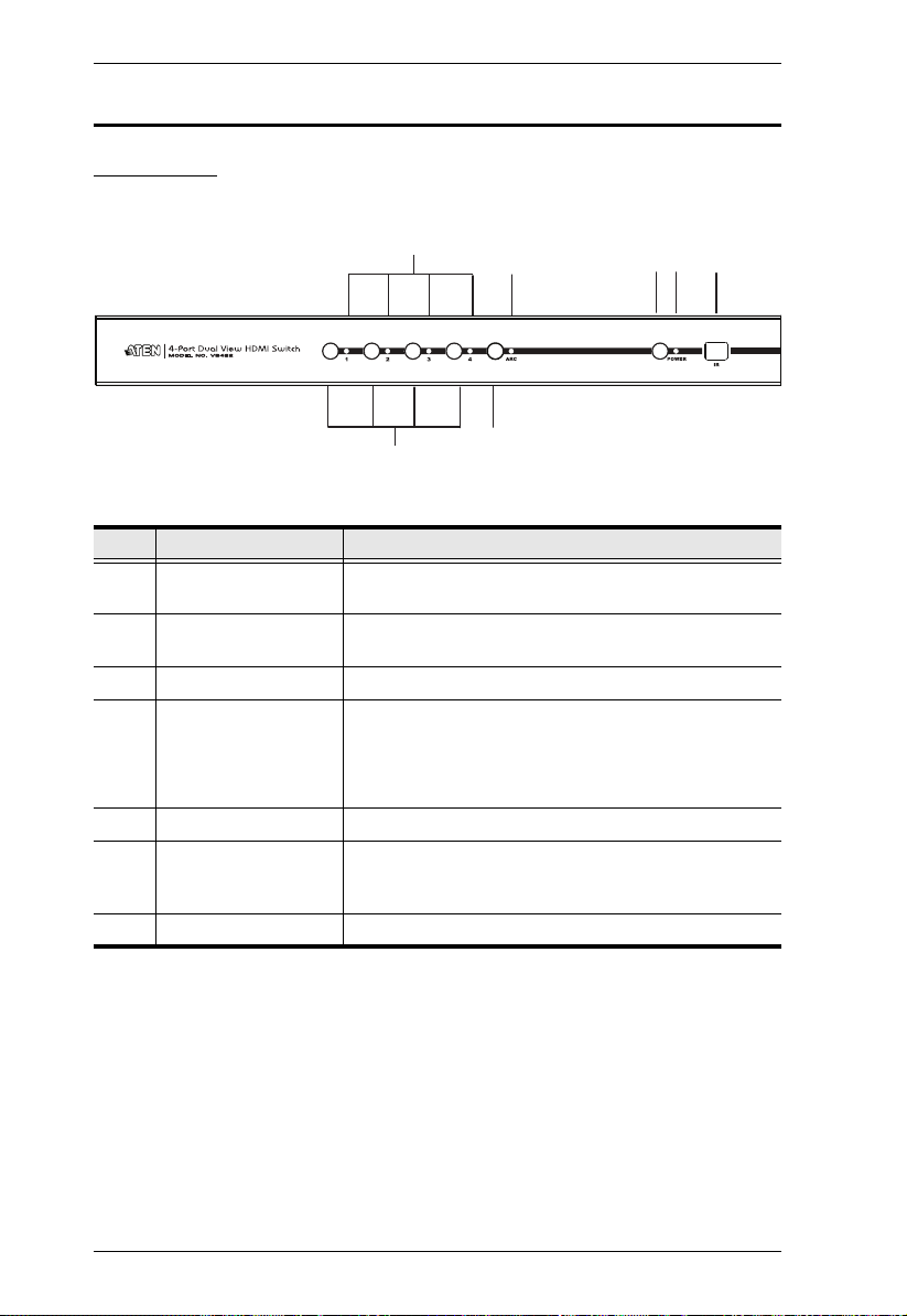
Components
Front View
No. Component Description
1 Port LEDs The SELECTED port’s LED (bottom, green) lights up
2 ARC LED The LED (blue) lights up when the ARC function is
3 Power Pushbutton Press this button to turn on / off the switch.
4 Power LED
5 IR Receiver This receives signals from the IR remote control.
6 Port Selection
Pushbuttons
7 ARC button Press this button to enable / disable the ARC function.
to indicate that the port is selected.
enabled.
The LED (green) lights up when the switch is
powered on.
The LED (orange) lights up to indicate that the
switch is in standby mode.
Pressing a port selection pushbutton routes the A/V
source from the corresponding input port to the output
port for display.
4
Chapter 1. Introduction
5
4
2
8
9
1
6
3
7
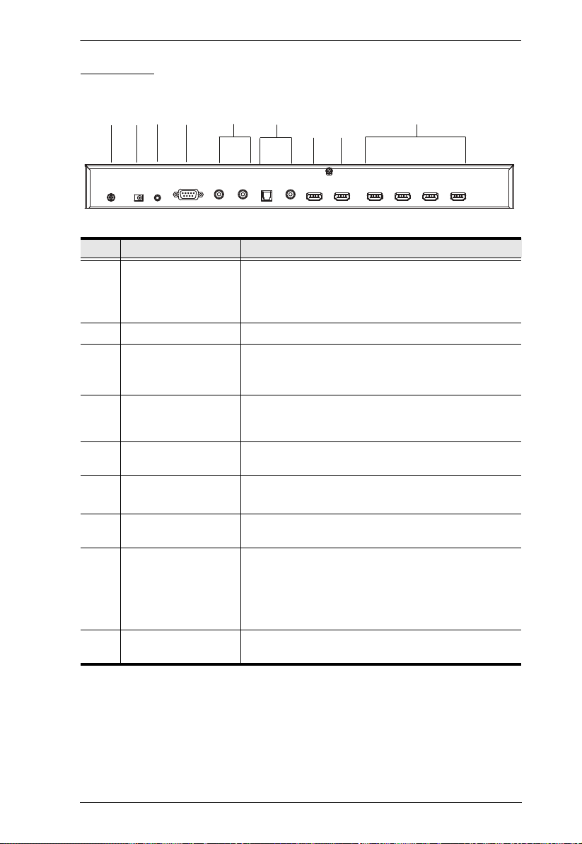
Rear View
No. Component Description
1 Grounding Terminal The grounding wire (used to ground the unit) attaches
2 Power Jack The power adapter cable plugs in here.
3 IR Extender Port Connect the IR Extender to this port.
4 RS-232 Serial Port This is the serial remote port for input source selection
5 Stereo Audio Ports The red port is for the right audio channel, and the
6 Digital Audio Ports Connect the optical and coaxial audio cables to these
here.
Note: The grounding wire is not included in this
package. Contact your dealer for more information.
Note: The additional IR receiver can be purchased
separately.
and high-end system control, including firmware
upgrade.
white port is for the left audio channel.
ports.
7 HDMI Out (port 2) The cable from the HDMI display or receiver device
8 HDMI Out (port 1)
(ARC In)
plugs in here.
The cable from the HDMI display device or receiver
plugs in here.
Connect the ARC audio input connector or receiver
to this port. The ARC audio can be transmitted back
(to audio receivers) through this connectivity
9 HDMI In The cables from the HDMI source devices can plug
into any of four available ports.
5
VS482 User Manual
1
2
5
6
7
3
4
9
8
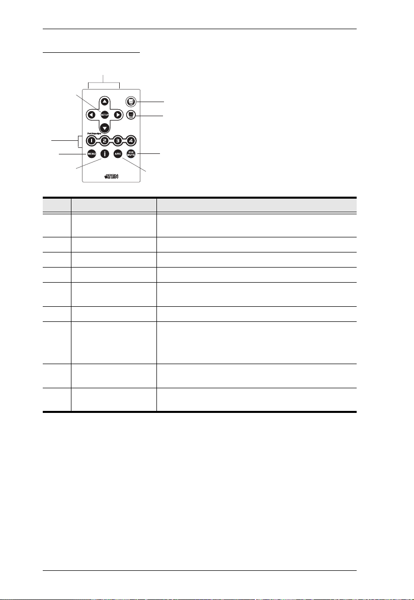
IR Remote Control
No. Component Description
1 Up / Down / Left /
Right Buttons
2 Setup Press this to confirm the selection on the OSD screen.
3 On Press this to power on the display.
4 Off Press this to power off the display.
5 Port Selection Buttons
1~4
6 Menu Press this to enable / disable the OSD menu.
7 Info button Press this button to display information about the
8 ARC Enable / Disable ARC function. See ARC Commands,
9 HDMI Mute Enable / Disable audio for the output HDMI port.
Press the Up / Down / Left / Right button to cycle
through the OSD menu/selection.
Press a button to bring the focus directly to the source
device attached to its associated port.
source device on the upper left side of the screen. The
information can include: Source port number; Source
port number + Source Type; or turned off.
page 23.
See Switch Mode, page 12.
6
Chapter 2
1. Important safety information regarding the placement of this
device is provided on page 39. Please review it before
proceeding.
2. Make sure that the power to all devices connected to the
installation are turned off.
3. Make sure that all devices you will be installing are properly
grounded.
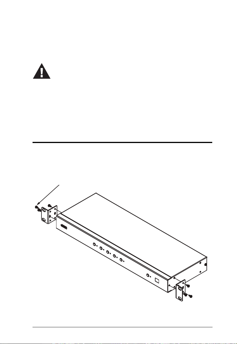
Phillips hex headPhillips hex head
M3x8M3x8
Hardware Setup
Rack Mounting
For convenience and flexibility, the VS482 can be mounted on system racks.
To rack mount a unit do the following:
1. Using the screws provided in the Mounting Kit, screw the mounting
bracket into the side of the unit as show in the diagram below:
7
VS482 User Manual
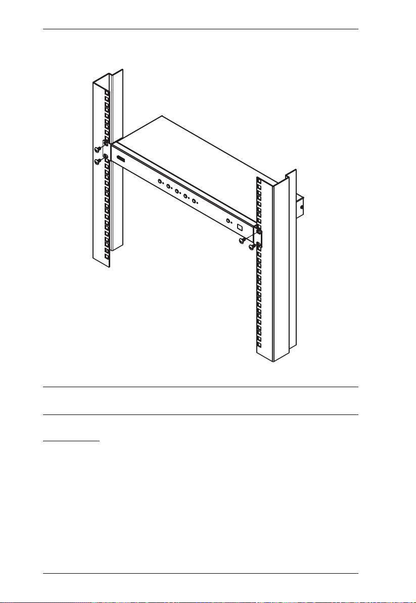
2. Screw the bracket into any convenient location on the rack.
Note: These screws are not provided. We recommend that you use M5 x 12
Phillips Type I cross, recessed type screws.
Grounding
To prevent damage to your installation it is important that all devices are
properly grounded.
1. Use a grounding wire to ground the VS482 by connecting one end of the
wire to the grounding terminal, and the other end of the wire to a suitable
grounded object.
2. Make sure that the computer(s)/device(s) that the VS482 connects to are
properly grounded.
8
 Loading...