

Page 1
VS481A HDMI Switch
RS-232 Control Tool
v1.0.064
User Manual
www.aten.com
Page 2
VS481A RS-232 Control Tool
FCC Information
This equipment has been tested and found to comply with the limits for a Class B digital
device, pursuant to Part 15 of the FCC Rules. These limits are designed to provide
reasonable protection against harmful interference in a residential installation. This
equipment generates, uses and can radiate radio frequency energy, and if not installed
and used in accordance with the instruction manual, may cause interference to radio
communications. However, there is no guarantee that interference will not occur in a
particular installation. If this equipment does cause harmful interference to radio or
television reception, which can be determined by turning the equipment off and on, the
user is encouraged to try to correct the interference by one or more of the following
measures:
Reorient or relocate the receiving antenna;
Increase the separation between the equipment and receiver;
Connect the equipment into an outlet on a circuit different from that which the
receiver is connected;
Consult the dealer or an experienced radio/television technician for help.
RoHS
This product is RoHS compliant.
SJ/T 11364-2006
The following contains information that relates to China.
2
Page 3

VS481A RS-232 Control Tool
RS-232 Control Tool Operation
Overview
The VS481A’s built-in bi-directional RS-232 serial interface allows system
control through a high-end controller, PC, and/or home automation / home
theater software package. RS-232 serial operations in a VS481
can be managed via a Graphical User Interface (GUI) on systems that are
running Windows. In order to use this Control Tool, two separate items of
software must be installed on all of the PCs in your installation – .NET
Framework 2.0 and the Control Tool AP. This procedure is detailed in the
following sections.
Before You Begin
.NET Framework 2.0
To install .NET Framework on your PC, do the following:
1. Download the executable file from the ATEN website or the Microsoft
Download Center online, and run it.
A installation
2. Follow the instructions on the screen. The installation applet will
automatically detect the operating system and install the correct drivers
RS-232 Control Tool AP
To download the RS-232 Control AP in order to use the Browser GUI to
manage the serial commands in your VS481
1. Download the RS-232 Control Tool AP from the ATEN website
(www.aten.com).
2. Save the file to a convenient location.
3. Run the file to open the RS-232 Control Tool GUI.
A installation, do the following:
3
Page 4

VS481A RS-232 Control Tool
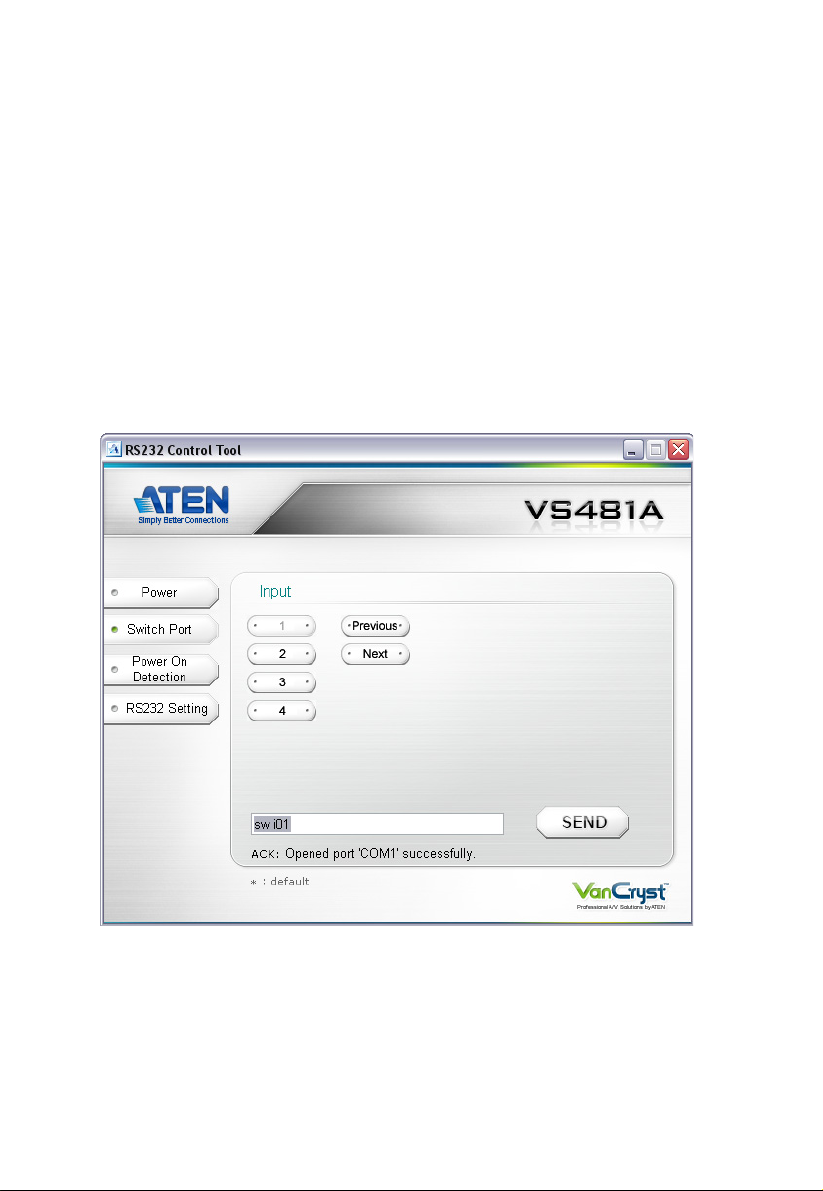
GUI Main Page
The RS232 Control Tool is a convenient and intuitive method to manage the
RS-232 commands in your VS481
GUI, simply click on the icon in your file system. The interface appears, and
opens on the Switch Port page by default, as below:
A installation from one screen. To invoke the
The various elements of the GUI are described in the following sections.
4
Page 5

VS481A RS-232 Control Tool
Switch Port
On the Switch Port page, the following actions are possible:
Click on a port number (1–4) to change the input to that port. Click Send
to send the command
Click Previous to change the input port to the previous port. Click Send to
send the command.
Click Next to change the input to the next port in the sequence. Click Send
to send the command.
Switch Port Commands
These actions can also be performed by keying the command into the text box,
and clicking Send.
The available formulas for Switch Port commands are as follows:
1. Switch Command + Input Port number + Output Port number [Enter]
For example, to switch input port 02 to output port 01, input the following:
sw i02 o01 [Enter]
2. Switch Command + Port Sequence [Enter]
For example, to switch to the next port, input the following:
sw + [Enter]
5
Page 6

VS481A RS-232 Control Tool
The following tables show the possible values and formats for the Input port,
Port Number and the Port Sequence:
Command Description
sw Switch command
I/O Port Description
i Input Port
Port number Description
xx 01-04 port (default is 01)
Port Sequence Description
+Next Port
-Previous Port
Note: 1. Each command string can be separated with a space.
2. The Input port command string can be skipped, and the default
value(s) will be used. For example, to switch the input port 01 to the
default output port, simply enter: sw i01.
6
Page 7

VS481A RS-232 Control Tool
Power
The Power page provides two options – Power On and Power Off, as shown
above.
To power on the device, click ON (or enter the command sw on in the text
box) and click Send.
To power off the device, click OFF (or enter the command sw off in the
text box) and click Send.
7
Page 8

VS481A RS-232 Control Tool
Power On Detection
The Power On Detection provides two options – Power On and Power Off, as
shown above.
To enable Power on Detection, click ON (or enter the command pod on in
the text box) and click Send.
To disable Power on Detection, click OFF (or enter the command pod off
in the text box) and click Send.
Power On Detection Commands
The formula for Power On Detection commands is as follows:
Power On Detection + Control command [Enter]
For example, to turn off the Power On Detection feature, input the following:
pod off [Enter]
The following tables show the possible values for the Control string
Command Description
pod Power On Detection command
Control Description
on Turn on
off Turn off
:
Note: The default setting for Power On Detection is ON.
8
Page 9

VS481A RS-232 Control Tool
RS-232 Setting
The controller’s serial port should be configured as follows:
Baud Rate 19200
Data Bits 8
Parity None
Stop B its 1
Flow Control None
To select the serial port, do the following:
Select a port from the drop-down menu and click CONNECT.
If the port has been selected, the Acknowledgment message will read:
Opened port COM1 successfully
Verification
After entering a command, a verification message appears at the end of the
command line as follows:
Command OK - indicates that the command is correct and successfully
performed by the switch
Command incorrect - indicates that the command has the wrong format
and/or values.
9
Page 10

VS481A RS-232 Control Tool
10
 Loading...