

Page 1

VS481A
USER MANUAL
HDMI Switch
Page 2
FCC Information
This equipment has been tested and f ound to comply with the limits
for a Class B digital device, pursuant to Part 15 of the FCC Rules.
These limits are designed to provide reasonable protection against
harmful interference in a residential installation. This equipment
generates, uses and can radiate radio frequency energy, and if not
installed and used in accordance with the instruction manual, may
cause interference to radio communic ati on s. However, ther e is no
guarantee that interference will not occur in a particular installation. If
this equipment does cause ha rmful interf erence to radio o r televisi on
reception, which can be determined by turning the equipment off and
on, the user is encourag ed to try to corr ect the i nterfer ence by one or
more of the following measures:
Reorient or relocate the re ceiving antenna;
Increase the separation betwee n the equipment and receiver;
Connect the equipment into an outlet on a circuit different from
that which the receiver is conn ected;
Consult the dealer or an experi enced radio/television technician
for help.
RoHS
This product is RoHS compliant.
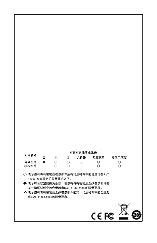
SJ/T 11364-2006
The following contains information that relates to China.
Page 3
VS481A User Manual
Online Registration
International http://support.aten.com
North America http://www.aten-u sa .com/ product_registration
Telephone Support
International 886-2-8692-6959
China 86-10-5255-0110
Japan 81-3-5615-5811
Korea 82-2-467-6789
North America 1-888-999-ATEN ext 4988
United Kingdom 44-8448-158923
Technical Support
For international online technical support – including
troubleshooting, documentation, and software updates:
http://support.aten.com
For North American technical support:
Email Support support@aten-usa.com
Online
Technical
Support
Telephone Support 1-888-999-ATEN ext 4998
Troubleshooting
Documentation
Software Updates
http://www.aten-usa.com/support
- 3 -
Page 4

Packa ge Conte nts
The VS481A HDMI Switch package contains the following items:
1 VS481A HDMI Switch
1 IR Remote Control Unit
1 Power Adapter
1 Standard HDMI Cable (1.8 m)
1 User Instructions*
Check to make sure that all the components are present and that
nothing got damaged in shipping. If you encounter a problem,
contact your dealer.
Read this manual thoroughly and follow the installation and
operation procedures carefully to prevent any damage to the unit,
and/or any of the devices connected to it.
* Features may have been added to the VS481A since this
manual was printed. Please visit our website to download the
most up-to-date version of the manual.
Copyright © 2008 – 2012 ATEN® International Co., Ltd.
Manual Part No. PAPE-1286-AT3G
ATEN and the ATEN logo are trademarks of ATEN International Co., Ltd. All rights
reserved. All other trademarks are the property of their respective owners.
Printing Date: 2012-02-02
- 4 -
Page 5

Overview
With more and more HDMI devices entering the Home Theater
market, the need for simultaneous access to different HDMI A/V
sources is becoming increasingly important. Now, the VS481
HDMI Switch offers an easy and affordable way to add HDMI
capabilities to your home theater system by allowing you to
switch easily between up to four HDMI A/V sources that are
connected to your HDMI display.
With four HDMI A/V input ports, the VS481
A HDMI Switch allows
you to connect four HDMI devices (such as an HD camcorder or
satellite box, HD-DVD player, hi-def Blu-ray player , home theater
PC, stand-alone streaming media player, or gaming console) to
your HDMI monitor, display , projector or TV at the same time. The
remote control and convenient front panel pushbuttons allow you
to quickly and easily toggle between A/V sources, while the front
panel LEDs indicate the source device at a glance.
For your convenience, the VS481
A has a single input port
mounted on the front panel for connecting mobile or temporary
devices, such as digital cameras, while your permanent device
connections are out of sight on the rear of the unit.
Furthermore, for complete system and install integration, RS232
control is standard through the VS481
A’s built-in bi-directional
RS-232 serial remote port that allows the switch to be controlled
through a high-end controller, PC, and/or home automation /
home theater software package.
A
- 5 -
Page 6

Features
Allows up to four HDMI A/V sources to be connected to one
HDMI display
Toggle between A/V sources using remote control or front
panel pushbuttons
Supports high-resolution video – HDTV resolutions of 480p,
720p, 1080i, 1080p (1920x1080); VGA, SVGA, SXGA, UXGA
(1600x1200), and WUXGA (1920 x 1200)
Supports Dolby True HD and DTS HD Master Audio
HDMI (3D, Deep Color)
Up to 60 Hz refresh rate
Long-distance transmission – up to 20 m
Built-in bi-directional RS-232 serial remote port for high-end
system control
Plug-and-play – no software installation required
DDC compatible
HDMI and HDCP compatible
Signaling rates up to 2.25 Gbits in support of 1080p display
All-metal casing
LED indication of A/V source devices
Power On Detection – if one of the HDMI source devices is
powered off, the VS481
powered on device
Easy and affordable way to add four HDMI inputs to your
home theater system
A will automatically switch to the next
- 6 -
Page 7

System Requirements
Source Device(s)
HDMI Type A output connector(s)
Note: A DVI/HDMI adapter is required when connecting a DVI
source device.
Display Device
A display device or receiver with an HDMI Type A input
connector
Cables
4 HDMI cables
Note: 1. Not all cables are included in this package. We strongly
recommend that you purchase high-quality cables of
appropriate length since this will affect the quality of the
audio and video display. Contact your dealer to
purchase the correct cable sets.
2. If you wish to utilize the VS481
controller function, you will also need to purchase an
appropriate RS-232 cable. See Installing the RS-232
Controller, page 11.
A’s high-end serial
- 7 -
Page 8

Components
VS481A Front View
2
A
1234
31
4
No. Component Function
1 HDMI In Plug the cable from an HDMI source
2 Port Selection
Pushbuttons
3 IR Receiver This receives signals from the IR remote
4 Port LEDs There are two port LEDs next to each port
device into this port (number 4).
Pressing a port selection pushbutton
routes the A/V source from the
corresponding input port to the output port
for display.
control.
selection pushbutton.
The ON LINE LED (top, orange) lights
up to indicate that the device attached
to the corresponding port is powered
on.
The SELECTED LED (bottom, green)
lights up to indicated that the port is
selected.
- 8 -
Page 9

VS481A Rear View
3
21 4
HDMI IN
HDMI IN
HDMI IN
HDMI OUT
32
1
No. Component Function
1 Power Jack The power adapter cable plugs in here.
2 HDMI Out The cable from the HDMI display device
3 HDMI In The cables from the HDMI source devices
4 RS-232 Serial
Port
plugs in here.
can plug into any of three available ports.
This is the serial remote port for input
source selection and high-end system
control.
- 9 -
Page 10

IR Remote Control
1
2
No. Component Function
1 Port Up / Port
Down Buttons
2 Port Selection
Buttons
Press the Port Up button to cycle forward
through the source devices (1 to 2; 2 to 3; 3 to
4; 4 to 1).
Press the Port Down button to cycle backward
through the source devices (4 to 3; 3 to 2; 2 to
1; 1 to 4).
Press a button to bring the focus directly to the
source device attached to its associated port.
- 10 -
Page 11

Installation
1. Make sure that the power to all devices you will be
installing has been turned off.
2. Make sure that all devices you will be installing are
properly grounded.
Installation of the VS481A is simply a matter of plugging in the
appropriate cables.
To install the switch, refer to the installation diagram on page 12
as you perform the following three steps:
1. Use an HDMI cable to connect the HDMI input port on the
video display device to the HDMI output port on the rear of
the VS481A.
2. Use HDMI cables to connect the HDMI output ports on the
source device(s) to the HDMI input ports on the VS481
Three HDMI input ports are located on the rear of the switch;
the fourth HDMI port is located on the front of the switch.
3. Plug the provided power adapter into an appropriate AC
power source; plug the power adapter cable into the Power
Jack on the VS481A.
This completes the basic installation of the VS481 A HDMI Switch.
You may now power on the display and source devices.
Installing the RS-232 Controller
In order to use the RS-232 serial interface to attach a high-end
controller (such as a PC) to the VS481
as a modem cable. The end connecting to the VS481
have a 9-pin male connector. Connect this to the serial interface
on the rear of the VS481
A. Refer to number 4 on the diagram on
page 12.
A, use a serial cable such
A.
A should
Note: To configure the controller serial port, see page 14.
- 11 -
Page 12

Installation Diagram
3
1
2
Hardware / Software
Controller
HDMI A/V
Source Devices
HDMI Output Device
4
OR
HDMI IN
HDMI IN
HDMI IN
HDMI OUT
32
1
- 12 -
Page 13

Source Device Selection
The VS481A HDMI Switch offers easy and flexible source device
selection with either the front panel pushbuttons, with the remote
control, or through the RS-232 serial interface.
Note: Whenever the VS481A is powered on, it automatically
selects Port 1 if there is no video input source connected.
You may choose one of the methods outlined below to
select a different port.
Manual Selection
To select a source device, press the pushbutton that corresponds
to the port it is connected to.
Note: The SELECTED LED (green) light indicates which port is
currently selected.
Remote Control Selection
To select a source device with the remote control, press the
number button that corresponds to the port it is connected to.
Alternatively, you may also cycle through the available source
devices by pushing the Port Up and Port Down buttons on the
remote control unit.
Use the Port Up button to select the next available port in
ascending order (from left to right on the front view panel).
Use the Port Down button to select the next available port in
descending order (from right to left on the front view panel).
Note: 1. The maximum range of the remote control unit is 10
meters (30 ft)
2. Aim the remote control unit at the IR receiver located on
the front panel of the VS481
performance, make sure there is a clear line-of-sight
between the remote control unit and the IR receiver.
A. For optimum
- 13 -
Page 14

Power ON Detection
The Power On Detection feature enables the switch to use the
next active port automatically when the active port is unplugged.
When the switch is turned on, the first plug in port acts as the
active port.
Note: The switch does not use the next active port if the current
port is not the active port and two active ports are turned
on.
RS-232 Serial Interface
The VS481A’s built-in bi-directional RS-232 serial interface
allows system control through a high-end controller, PC, and/or
home automation / home theater software package.
Configuring the Serial Port
The controller’s serial port should be configured as follows:
Baud Rate 19200
Data Bits 8
Parity None
Stop Bits 1
Flow Control None
Switch Port Commands
The formulas for Switch Port commands are as follows:
1. Switch Command + Input Port number + Output Port number
[Enter]
For example, to switch input port 02 to output port 01, input the
following:
sw i02 o01 [Enter]
2. Switch Command + Port Sequence [Enter]
- 14 -
Page 15

For example, to switch to the next port, input the following:
sw + [Enter]
The following tables show the possible values and formats for the
Input / Output port, Port Number and the Port Sequence:
Command Description
sw Switch command
I/O Port Description
i Input Port
o
Port number Description
xx 01-04 port (default is 01)
yy
Port Sequence Description
+Next Port
-
Output Port
01 port (default is 01)
Previous Port
Note: 1. Each command string can be separated with a space.
2. The Input / Output port command string can be
skipped, and the default value(s) will be used. For
example, to switch the input port 01 to the default output
port 01, simply enter: sw i01.
3. The input port and output port command strings are
interchangeable. For example: sw i02 o01 can also be
sw o01 i02.
- 15 -
Page 16

Power On Detection Commands
The Power On Detection feature is turned on by default.
The formula for Power On Detection commands is as follows:
Power On Detection + Control command [Enter]
For example, to turn off the Power On Detection feature, input the
following:
pod off [Enter]
The following tables show the possible values for the Control
string
:
Command Description
pod Power On Detection command
Control Description
on Turn on
off
Turn off
Note: Each command can be separated with a space.
Verification
After entering a command, a verification message appears at the
end of the command line as follows:
Command OK - indicates that the command is correct and
successfully performed by the switch
Command incorrect - indicates that the command has the
wrong format and/or values.
- 16 -
Page 17

Powering Off and Restarting
If you power off the VS481A, follows these steps before powering
it on again:
1. Power off the attached devices.
2. Unplug the power adapter cable from the VS481
3. Wait 10 seconds, and then plug the power adapter cable back
in.
4. After the VS481
devices.
Note: Whenever the VS481A is powered on, it automatically
selects the A/V source attached to Port 1.
A is powered on, power on the attached
A.
- 17 -
Page 18

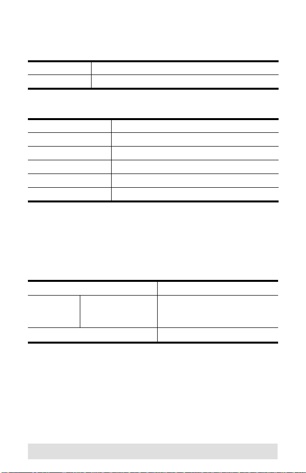
Specifications
Function VS481A
Display Connections 1
Connectors Device HDMI In 4 x HDMI Type A Female (Black)
Display HDMI Out 1 x HDMI Type A Female (Black)
RS-232 Port 1 x DB-9 Female (Black)
Power 1 x DC Jack
LEDs On Line 4 (Orange)
Selected 4 (Green)
Buttons Port Switch 4
IR Control 1
HDMI Resolution HDTV resolutions of 480p, 720p, 1080i,
Power Consumption DC5.3V, 2.4 W
Environment Operating Temp. 0–50ºC
Storage Temp. -20–60ºC
Humidity 0–80% RH, Non-condensing
Physical
Properties
Housing Metal
Weight 0.47 kg
Dimensions
(L x W x H)
1080p (1920x1080); WUXGA (1920 x
1200)
20.00 x 8.00 x 2.50 cm
- 18 -
Page 19

Limited Warranty
IN NO EVENT SHALL THE DIRECT VENDOR'S LIABILITY EXCEED THE PRICE
PAID FOR THE PRODUCT FROM THE DIRECT, INDIRECT, SPECIAL,
INCIDENTAL OR CONSEQUENTIAL DAMAGES RESULTING FROM THE USE
OF THE PRODUCT, DISK OR ITS DOCUMENTATION.
The direct vendor makes no warranty or representation, expressed, implied, or
statutory with respect to the contents or use of this documentation, and specially
disclaims its quality, performance, merchantability, or fitness for any particular
purpose.
The direct vendor also reserves the right to revise or update the device or
documentation without obligation to notify a ny individual or ent ity of such revisions,
or update. For further inquires please contact your direct vendor.
- 19 -
 Loading...