

Page 1

Video Splitter
USER MANUAL
VS-104 / VS-108
Page 2

FCC Information
WARNING!!! This equipment generates, uses, and can radiate radio
frequency energy and if not installed and used in accordance with the
instruction manual, may cause interference to radio communications.
It has been tested and found to comply with the limits for a Class A
computing device pursuant to Subpart J of Part 15 of FCC Rules,
which are designed to provide reasonable protection against such
interference when operated in a commercial environment. Operation
of this equipment in a residential area is likely to cause interference in
which case the user at his own expense will be required to take
whatever measures may be required to correct the interference.
Page 3

VS-104 / VS-108 User Manual
Packa ge C ontents
The VS-102 Video Splitter package contains the following items:
1 VS-104 or VS-108 Video Splitter
1 Power Adapter
1 User Manual*
1 Quick Start Guide
Check to make sure that all the components are present and that
nothing got damaged in shipping. If you encounter a problem,
contact your dealer.
Read this manual thoroughly and follow the installation and
operation procedures carefully to prevent any damage to the unit,
and/or any of the devices connected to it.
* Features may have been added to the VS-104 / VS-108 since
this manual was printed. Please visit our website to download
the most up-to-date version of the manual.
Copyright © 2006 ATEN® International Co., Ltd.
Manual Part No. PAPE-XXXX-XXXX
ATEN and the ATEN logo are trademarks of ATEN International Co., Ltd. All rights
reserved. All other trademarks are the property of their respective owners.
Manual Date: 2008-06-11
- 3 -
Page 4
Overview
The VS-104 / VS-108 Video Splitter is a boosting device to
duplicate the video signal from one source to 4 (VS-104) or 8
(VS-108) outputs, and is ideal for any monitor using analog
signals. The VS-104 and VS-108 also extend the transmission
distance up to 210 feet making them excellent for public
broadcast systems.
To get multiple, high quality, VGA, SVGA or Multisync video
signals over long distances without hassle, the VS-104 and
VS-108 are your best choice.
- 4 -
Page 5

Features
One Video Input to 4/8 Video Outputs
Transmission Distance: 65m (210ft.)
Suitable for SVGA, VGA and Multisync Monitors
Daisy Chainable
Power Saving Mode: Power LED Flashes to Indicate When
Computer Is Off.
Supports one XGA or VESA DDC Port (Video Out 1)
DDC Compatible
Requirements
If you connect a DDC type monitor to Video Out 1, all
other monitors must be able to support the highest
video resolution that the DDC monitor can provide.
- 5 -
Page 6

Front and Rear Views
Note: 1. This product is not suitable for CGA, EGA, or
Monochrome type monitors using a digital video signal.
2. UL2919 rated cable is recommended for the best video
quality.
- 6 -
Page 7

Installation
Standalone Installation
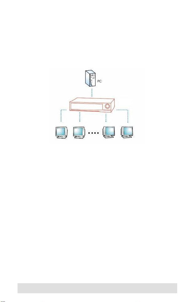
1. Connect the video signal from the PC to the VIDEO IN port of
the Video Splitter with a high density HD-15 cable.
2. Connect the VIDEO OUT ports of the Video Splitter to the
display monitors with high density HD-15 cables.
3. Plug the power adapter that came with this product into an
AC source; plug the power adapter cable into the DC IN
socket on the Video Splitter's rear panel.
4. Power on the Video Splitter.
5. There is a gain control switch on the bottom panel. For
optimum video display, slide it toward the front panel for high
gain (longer distance operation); slide it toward the rear panel
for normal Gain (shorter distance operation).
Daisy Chain Installation
Both the VS-104 and VS-108 can be daisy chained:
1. Connect the Video Splitter's VIDEO OUT port to any VIDEO
IN port of the lower stage Video Splitter with a Male to Female
HD-15 cable.
2. Plug the Power Adapter into an AC source; plug the Power
Adapter cable into the DC IN socket on the Video Splitter's
rear panel.
3. Power on the Video Splitter.
4. Adjust the gain control switch for optimum video display.
5. Repeat steps 1 - 4 to daisy chain additional units.
- 7 -
Page 8

Installation Diagram
- 8 -
Page 9

Specifications
Function
Connectors Input 1 High Density HD-15 M
Output 4 High Density HD-15 F 8 High Density HD-15 F
VGA Bandwidth (-3db) 250 MHz 200 MHz
VGA Res/Vert Freq. 1920 x 1440 @60 Hz 1600 x 1200 @60 Hz
Power Consumption DC 9V, 180mA (max.) DC 9V, 380mA (max.)
LEDs 1 Power Indicator
Cable Distance 65M (210ft.) (max.)
Signal Type VGA, XGA, SVGA, UXGA, Multisync
Slide Switch Video Signal Gain Control
Housing Plastic & Metal
Weight 1.20 kg 1.30 kg
Dimensions (L x W x H) 22.40 x 15.20 x 5.20 cm
VS-104 VS-108
- 9 -
Page 10

HD-15 Pin Assignments
Video In
Pin Assignment Pin Assignment
1 Red video input 9 No pin
2 Green video input 10 Logic ground
3 Blue video input 11 ID bit
4 Ground 12 Serial data line (SDA)
5 Ground 13 H. Sync / H+V
6 Ground 14 V Sync (VCLK for DDC)
7 Ground 15 Data clock line (SCL)
8 Ground
Video Out
Pin Assignment Pin Assignment
1 Red video input 9 No pin
2 Green video input 10 Ground
3 Blue video input 11 ID bit
4 ID bit 12 Serial data line (SDA)
5 Ground 13 H. Sync / H+V
6 Ground 14 V Sync (VCLK for DDC)
7 Ground 15 No pin
8 Ground
- 10 -
Page 11

Limited Warranty
IN NO EVENT SHALL THE DIRECT VENDOR'S LIABILITY EXCEED THE PRICE
PAID FOR THE PRODUCT FROM THE DIRECT, INDIRECT, SPECIAL,
INCIDENTAL OR CONSEQUENTIAL DAMAGES RESULTING FROM THE USE
OF THE PRODUCT, DISK OR ITS DOCUMENTATION.
The direct vendor makes no warranty or representation, expressed, implied, or
statutory with respect to the contents or use of this documentation, and specially
disclaims its quality, performance, merchantability, or fitness for any particular
purpose.
The direct vendor also reserves the right to revise or update the device or
documentation without obligation to notify any individual or entity of such revisions,
or update. For further inquires please contact your direct vendor.
- 11 -
 Loading...