

Page 1

VS0801
USER MANUAL
8-Port Video Switch
Page 2
FCC Information
This is an FCC Class A product. In a domestic environment this
product may cause radio interference in which case the user may be
required to take adequate measures.
This equipment has been tested and found to comply with the limits
for a Class A digital device, pursuant to Part 15 of the FCC Rules.
These limits are designed to provide reasonable protection against
harmful interference when the equipment is operated in a commercial
environment. This equipment generates, uses and can radiate radio
frequency energy and, if not installed and used in accordance with the
instruction manual, may cause harmful interference to radio
communications. Operation of this equipment in a residential area is
likely to cause harmful interference in which case the user will be
required to correct the interference at his own expense.
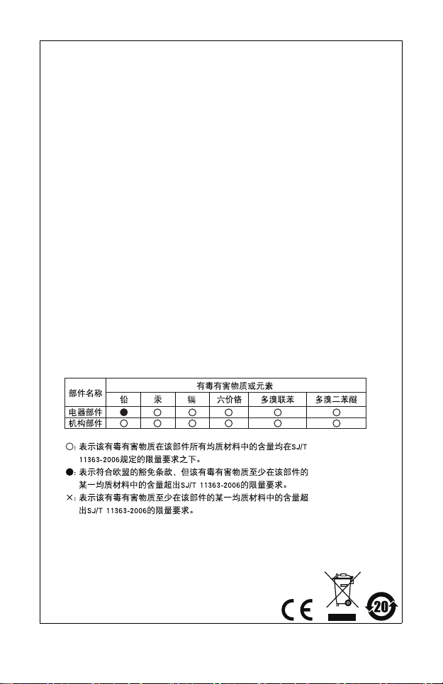
RoHS
This product is RoHS compliant.
SJ/T 11364-2006
The following contains information that relates to China.
Page 3
VS0801 User Manual
Online Registration
International http://support.aten.com
North America http://www.aten-usa.com/product_registration
Telephone Support
International 886-2-8692-6959
China 86-10-5255-0110
Japan 81-3-5323-7178
Korea 82-2-467-6789
North America 1-888-999-ATEN ext 4988
United Kingdom 44-8448-158923
Technical Support
For international online technical support – including
troubleshooting, documentation, and software updates:
http://support.aten.com
For North American technical support:
Email Support support@aten-usa.com
Online
Technical
Support
Telephone Support 1-888-999-ATEN ext 4998
Troubleshooting
Documentation
Software Updates
http://www.aten-usa.com/support
- 3 -
Page 4

Packa ge C ontents
The VS0801 8-port Video Switch package contains the following
items:
1 VS0801 8-port Video Switch
1 VGA/Audio Cable (1.8 m)
1 IR Remote Control Unit
1 Power Adapter
1 Rack Mount Kit
1 User Manual*
1 Quick Start Guide
Check to make sure that all the components are present and that
nothing got damaged in shipping. If you encounter a problem,
contact your dealer.
Read this manual thoroughly and follow the installation and
operation procedures carefully to prevent any damage to the unit,
and/or any of the devices connected to it.
* Features may have been added to the VS0801 since this
manual was printed. Please visit our website to download the
most up-to-date version of the manual.
Copyright © 2010 ATEN® International Co., Ltd.
Manual Part No. PAPE-1348-AT1G
ATEN and the ATEN logo are trademarks of ATEN International Co., Ltd. All rights
reserved. All other trademarks are the property of their respective owners.
Printing Date: 2010-04-23
- 4 -
Page 5

Overview
With eight VGA/Audio input ports, the VS0801 8-port Video
Switch allows you to conveniently display the video output of
eight separate computer systems on all analog monitors or a
multimedia projector. Rack mountable in only 1U of space, and
with full audio support, the VS0801 is perfect for server room
applications that require the monitoring of high quality video and
audio output, allowing you to monitor work harsh environments
from a safe location.
The IR remote control and convenient front panel pushbuttons
allow you to quickly and easily toggle between VGA/Audio
sources, while the front panel LEDs indicate the source device at
a glance. In addition, with support for up to 300 MHz bandwidth,
the VS0801 allows for the transmission of large amounts of
information at very high speeds.
Furthermore, for complete system and install integration, RS-232
control is standard through the VS0801’s built-in bi-directional
RS-232 serial port that allows the switch to be controlled through
a serial PC.
Designed for enterprise use, the VS0801 eliminates the extra
cost of purchasing a separate monitor for each computer system,
saves space and power in the server room, and provides high
speed audio and video for a wide range of industrial and
commercial applications.
- 5 -
Page 6

Features
Displays the video output of up to eight computers on a single
analog display
Quick and easy switching between VGA/Audio sources via
front panel pushbuttons or IR remote control
Supports stereo audio
Built-in bi-directional RS-232 serial port for high-end system
control
Supports up to 300 MHz bandwidth
Superior video quality – 2048x1536@60Hz; DDC; DDC2;
DDC2B
Supports all analog displays – VGA, SVGA, UXGA, WUXGA,
and multisync
Plug-and-play – no software installation required
All-metal casing provides durability and protection
Designed for enterprise use
Rack Mountable
- 6 -
Page 7

System Requirements
Source Devices(s)
The following equipment must be installed on the source device
or computer that acts as a source of VGA/Audio content:
HDB-15 connector
Display Device
A VGA, SVGA, UXGA, WUXGA or multisync monitor or
multimedia projector with an HDB-15 connector
Cables
1 VGA/Audio cable for each source device you will be
connecting
1 VGA/Audio cable for your display device
Note: 1. One 1.8 m VGA/Audio cable is included in this package.
We strongly recommend that you purchase high-quality
cables of appropriate length since this will affect the
quality of the audio and video display. Contact your
dealer to purchase the correct cable sets.
2. If you wish to utilize the VS0801’s high-end serial
controller function, you will also need to purchase an
appropriate RS-232 cable. See Installing the RS-232
Controller, page 11.
- 7 -
Page 8

Components
2
1
3
VS0801 Front View
No. Component Function
1 Port Selection
Pushbuttons
2 Port LEDs There is one port LED next to each port
3 IR Receiver This receives signals from the IR remote
Pressing a port selection pushbutton
routes the VGA/Audio source from the
corresponding input port to the output port
for display.
selection pushbutton. This lights green to
indicate that the corresponding port has
been selected. Port LED flashes when
video output is disabled.
control.
- 8 -
Page 9

VS0801 Rear View
1
2
3
VIDEO / AUDIO OUT
8765
4321
4
5
No. Component Function
1 Grounding
Te rm i n al
2 RS-232 Serial
Port
3 Video / Audio
Input
4 Power Jack The power adapter cable plugs in here.
5 Video / Audio
Output
The grounding wire (used to ground the
unit) attaches here.
This is the serial remote port for input
source selection and high-end system
control.
Each input section is comprised of a VGA
connector and a mini stereo audio jack.
The cables that connect to the video and
audio output ports on the computers /
source devices plug in here.
The cables that connect to the video and
audio input ports on the video display plug
in here.
- 9 -
Page 10

IR Remote Control
1
2
ON / OFF
No. Component Function
1 Port Up / Port
Down Buttons
Press the Port Up button to cycle forward
through the source devices (1 to 2; 2 to 3; ... 8
to 1).
Press the Port Down button to cycle backward
through the source devices. (8 to 7; 7 to 6; ... 1
to 8)
2 Port Selection
Buttons
3On / Off
Button
Press a button to bring the focus directly to the
source device attached to its associated port.
This button enables / disables the video
output.
Note: If video output is disabled, the
corresponding port LED will flash until video is
re-enabled.
3
- 10 -
Page 11

Installation
1. Make sure that the power to all devices you will be
installing has been turned off.
2. Make sure that all devices you will be installing are
properly grounded.
Installation of the VS0801 is simply a matter of plugging in the
appropriate cables.
To install the switch, refer to the installation diagram on page 12
as you perform the following three steps:
1. Use a VGA cable to connect the VGA input port on the video
display device to the VGA output ports on the rear of the
VS0801. Connect your speakers to the Audio output port.
2. Use VGA/Audio cables to connect the VGA/Audio output
ports on the source device(s) to the VGA/Audio input ports on
the VS0801. Eight VGA/Audio input ports are located on the
rear of the switch.
3. Plug the provided power adapter into an appropriate AC
power source; plug the power adapter cable into the Power
Jack on the VS0801.
This completes the basic installation of the VS0801 8-port Video
Switch. You may now power on the display and source devices.
Installing the RS-232 Controller
In order to use the RS-232 serial interface to attach a high-end
controller (such as a PC) to the VS0801, use a serial cable such
as a modem cable. The end connecting to the VS0801 should
have a 9-pin male connector. Connect this to the serial interface
on the rear of the VS0801. Refer to number 4 on the diagram on
page 12.
Note: To configure the controller serial port, see page 14.
- 11 -
Page 12

Installation Diagram
Hardware / Software
Controller
4
3
2
1
OR
VIDEO / AUDIO OUT
8765
4321
- 12 -
Page 13

Source Device Selection
The VS0801 8-port Video Switch offers easy and flexible source
device selection with either the front panel pushbuttons, with the
remote control, or through the RS-232 serial interface.
Note: Whenever the VS0801 is powered on, it automatically
selects the first port. You may choose one of the methods
outlined below to select a different port.
Manual Selection
To select a source device, press the pushbutton that corresponds
to the port it is connected to.
Note: The SELECTED LED (green) light indicates which port is
currently selected.
Remote Control Selection
To select a source device with the remote control, press the
number button that corresponds to the port it is connected to.
Alternatively, you may also cycle through the source devices by
pushing the Port Up and Port Down buttons on the remote control
unit.
Use the Port Up button to select the next port in ascending
order (from left to right on the front view panel).
Use the Port Down button to select the next port in
descending order (from right to left on the front view panel).
Note: Aim the remote control unit at the IR receiver located on
the front panel of the VS0801. For optimum performance,
make sure there is a clear line-of-sight between the
remote control unit and the IR receiver.
- 13 -
Page 14

RS-232 Serial Interface
The VS0801’s built-in bi-directional RS-232 serial interface
allows system control through a high-end controller or PC.
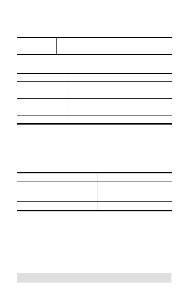
Configuring the Serial Port
The controller’s serial port should be configured as follows:
Baud Rate 19200
Data Bits 8
Parity None
Stop Bi ts 1
Flow Control None
- 14 -
Page 15

Serial Commands
The VS0801’s serial commands are as follows
Control
Function
Protocol
Switch to
Last Port
Switch to
Next Port
Switch to
Port 1
Switch to
Port 2
Switch to
Port 3
Switch to
Port 4
Switch to
Port 5
Switch to
Port 6
Switch to
Port 7
Switch to
Port 8
Start
Head Function
Code
0x5A
Port
0x7E
Code
0x81
Switch to Next
Port 0x00
Switch to Next
Port 0x01
Switch to Next
Port 0x08
Packet Format
Data
Data Checksum
Length
0x00 N/A 0x81 0x81
N/A 0x82
0x01 0x31 0xBB
0x32 0xBC
0x33 0xBD
0x34 0xBE
0x35 0xBF
0x36 0xC0
0x37 0xC1
0x38 0xC2
End
Code
0xA5
- 15 -
Page 16

Powering Off and Restarting
If you power off the VS0801, follows these steps before powering
it on again:
1. Power off the attached devices.
2. Unplug the power adapter cable from the VS0801.
3. Wait 10 seconds, and then plug the power adapter cable back
in.
4. After the VS0801 is powered on, power on the attached
devices.
Note: Whenever the VS0801 is powered on, it automatically
selects the first port.
- 16 -
Page 17

Specifications
Function VS0801
Display Connections 1
Connectors Device Video In 8 x HDB-15 Male (Blue)
Audio In 8 x Mini Stereo Jack Female (Green)
Display Video Out 1 x HDB-15 Female (Blue)
Audio Out 1 x Mini Stereo Jack Female (Green)
RS-232 Port 1 x DB-9 Female (Black)
Power 1 x DC Jack
LEDs Selected 8 (Green)
Video 2048 x 1536@60 Hz; DDC2B
Power Consumption DC5.3V, 1.01W
Environment Operating Temp. 0–50ºC
Storage Temp. -20–60ºC
Humidity 0–80% RH, Non-condensing
Physical
Properties
Housing Metal
Weight 2.10 kg
Dimensions
(L x W x H)
43.2 x 15.4 x 4.4 cm
- 17 -
Page 18

Limited Warranty
IN NO EVENT SHALL THE DIRECT VENDOR'S LIABILITY EXCEED THE PRICE
PAID FOR THE PRODUCT FROM THE DIRECT, INDIRECT, SPECIAL,
INCIDENTAL OR CONSEQUENTIAL DAMAGES RESULTING FROM THE USE
OF THE PRODUCT, DISK OR ITS DOCUMENTATION.
The direct vendor makes no warranty or representation, expressed, implied, or
statutory with respect to the contents or use of this documentation, and specially
disclaims its quality, performance, merchantability, or fitness for any particular
purpose.
The direct vendor also reserves the right to revise or update the device or
documentation without obligation to notify any individual or entity of such revisions,
or update. For further inquires please contact your direct vendor.
- 18 -
 Loading...