

7 x 3 Seamless Presentation Switch
with Streaming, HDBaseT
VP2730 User Manual
www.aten.com

VP2730 User Manual
Preface
EMC Information
FEDERAL COMMUNICATIONS COMMISSION INTERFERENCE
STATEMENT: This equipment has been tested and found to comply with the
limits for a Class A digital device, pursuant to Part 15 of the FCC Rules. These
limits are designed to provide reasonable protection against harmful
interference when the equipment is operated in a commercial environment. This
equipment generates, uses, and can radiate radio frequency energy and, if not
installed and used in accordance with the instruction manual, may cause
harmful interference to radio communications. Operation of this equipment in a
residential area is likely to cause harmful interference in which case the user will
be required to correct the interference at his own expense.
FCC Caution: Any changes or modifications not expressly approved by the
party responsible for compliance could void the user's authority to operate this
equipment.
CE Warning: Operation of this equipment in a residential environment could
cause radio interference.
This device complies with Part 15 of the FCC Rules. Operation is subject to the
following two conditions:
(1) this device may not cause harmful interference, and
(2) this device must accept any interference received, including interference
that may cause undesired operation.
Suggestion: Shielded twisted pair (STP) cables must be used with the unit to
ensure compliance with FCC & CE standards.
RoHS
This product is RoHS compliant.
ii
VP2730 User Manual
User Information
Online Registration
Be sure to register your product at our online support center:
International http://eservice.aten.com
Telephone Support
For telephone support, call this number:
International 886-2-8692-6959
China 86-400-810-0-810
Japan 81-3-5615-5811
Korea 82-2-467-6789
North America 1-888-999-ATEN ext 4988
1-949-428-1111
User Notice
All information, documentation, and specifications contained in this manual are
subject to change without prior notification by the manufacturer. The
manufacturer makes no representations or warranties, either expressed or
implied, with respect to the contents hereof and specifically disclaims any
warranties as to merchantability or fitness for any particular purpose. Any of the
manufacturer's software described in this manual is sold or licensed as is.
Should the programs prove defective following their purchase, the buyer (and
not the manufacturer, its distributor, or its dealer), assumes the entire cost of all
necessary servicing, repair and any incidental or consequential damages
resulting from any defect in the software.
The manufacturer of this system is not responsible for any radio and/or TV
interference caused by unauthorized modifications to this device. It is the
responsibility of the user to correct such interference.
The manufacturer is not responsible for any damage incurred in the operation
of this system if the correct operational voltage setting was not selected prior to
operation. PLEASE VERIFY THAT THE VOLTAGE SETTING IS CORRECT
BEFORE USE.
iii

VP2730 User Manual
Package Contents
1 VP2730 7 x 3 Seamless Presentation Matrix Switch
1 IR Receiver
1 IR Remote Control
1 Power Cord
2 Terminal Blocks
4 Foot Pads
1 User Instructions
Note: Make sure that all of the items are present and in good order. If anything
is missing or was damaged in shipping, please contact your dealer for
further assistance.
iv

VP2730 User Manual
Table of Contents
Preface
EMC Information. . . . . . . . . . . . . . . . . . . . . . . . . . . . . . . . . . . . . . . . . . . . . ii
RoHS . . . . . . . . . . . . . . . . . . . . . . . . . . . . . . . . . . . . . . . . . . . . . . . . . . . . . ii
User Information . . . . . . . . . . . . . . . . . . . . . . . . . . . . . . . . . . . . . . . . . . . .iii
Package Contents . . . . . . . . . . . . . . . . . . . . . . . . . . . . . . . . . . . . . . . . . . .iv
About this Manual . . . . . . . . . . . . . . . . . . . . . . . . . . . . . . . . . . . . . . . . . . vii
Conventions . . . . . . . . . . . . . . . . . . . . . . . . . . . . . . . . . . . . . . . . . . . . . . . viii
Product Information . . . . . . . . . . . . . . . . . . . . . . . . . . . . . . . . . . . . . . . . . viii
1. Introduction
Overview. . . . . . . . . . . . . . . . . . . . . . . . . . . . . . . . . . . . . . . . . . . . . . . . . . . 1
Features . . . . . . . . . . . . . . . . . . . . . . . . . . . . . . . . . . . . . . . . . . . . . . . . . . . 2
Planning the Installation . . . . . . . . . . . . . . . . . . . . . . . . . . . . . . . . . . . . . . . 4
Required Equipment . . . . . . . . . . . . . . . . . . . . . . . . . . . . . . . . . . . . . . . 4
Optional Equipment. . . . . . . . . . . . . . . . . . . . . . . . . . . . . . . . . . . . . . . . 4
2. Hardware Setup
Components . . . . . . . . . . . . . . . . . . . . . . . . . . . . . . . . . . . . . . . . . . . . . . . . 5
VP2730 Front View . . . . . . . . . . . . . . . . . . . . . . . . . . . . . . . . . . . . . . . . 5
VP2730 Rear View . . . . . . . . . . . . . . . . . . . . . . . . . . . . . . . . . . . . . . . . 6
IR Remote Control . . . . . . . . . . . . . . . . . . . . . . . . . . . . . . . . . . . . . . . . 8
LED Display . . . . . . . . . . . . . . . . . . . . . . . . . . . . . . . . . . . . . . . . . . . . . 9
Rack Mount. . . . . . . . . . . . . . . . . . . . . . . . . . . . . . . . . . . . . . . . . . . . . . . . 10
Installation . . . . . . . . . . . . . . . . . . . . . . . . . . . . . . . . . . . . . . . . . . . . . . . . 11
3. Local Operation
Overview. . . . . . . . . . . . . . . . . . . . . . . . . . . . . . . . . . . . . . . . . . . . . . . . . . 13
Operation Considerations . . . . . . . . . . . . . . . . . . . . . . . . . . . . . . . . . . 13
Switching the Display Source . . . . . . . . . . . . . . . . . . . . . . . . . . . . . . . . . 14
Using the IR Remote Control / Front-panel Pushbutton . . . . . . . . . . . 14
Using the OSD . . . . . . . . . . . . . . . . . . . . . . . . . . . . . . . . . . . . . . . . . . 16
Launching the OSD . . . . . . . . . . . . . . . . . . . . . . . . . . . . . . . . . . . . . . . . . 18
Configuring the Multiview . . . . . . . . . . . . . . . . . . . . . . . . . . . . . . . . . . . . . 21
Changing the Display Mode . . . . . . . . . . . . . . . . . . . . . . . . . . . . . . . . . . . 23
Moderator Mode (Remote Display Control) . . . . . . . . . . . . . . . . . . . . . . . 25
Locking the Front Panel . . . . . . . . . . . . . . . . . . . . . . . . . . . . . . . . . . . . . . 27
System Settings . . . . . . . . . . . . . . . . . . . . . . . . . . . . . . . . . . . . . . . . . . . . 28
v

VP2730 User Manual
4. Remote Operation
Overview . . . . . . . . . . . . . . . . . . . . . . . . . . . . . . . . . . . . . . . . . . . . . . . . . .33
Supported Web Browsers . . . . . . . . . . . . . . . . . . . . . . . . . . . . . . . . . .33
The VP2730’s IP Address . . . . . . . . . . . . . . . . . . . . . . . . . . . . . . . . .34
The Participant Account . . . . . . . . . . . . . . . . . . . . . . . . . . . . . . . . . . . . . . 35
Logging in as Participant . . . . . . . . . . . . . . . . . . . . . . . . . . . . . . . . . . . 35
The Participant Screen . . . . . . . . . . . . . . . . . . . . . . . . . . . . . . . . . . . .36
Sharing a Screen or an Application Window . . . . . . . . . . . . . . . . . . .37
The Administrator Account . . . . . . . . . . . . . . . . . . . . . . . . . . . . . . . . . . . .40
Logging in as Administrator. . . . . . . . . . . . . . . . . . . . . . . . . . . . . . . . .40
The Administrator Screen . . . . . . . . . . . . . . . . . . . . . . . . . . . . . . . . . . 42
Configuration View. . . . . . . . . . . . . . . . . . . . . . . . . . . . . . . . . . . . . 42
Presentation View . . . . . . . . . . . . . . . . . . . . . . . . . . . . . . . . . . . . . 43
System Configuration . . . . . . . . . . . . . . . . . . . . . . . . . . . . . . . . . . . . .44
General Settings . . . . . . . . . . . . . . . . . . . . . . . . . . . . . . . . . . . . . .44
Audio Settings . . . . . . . . . . . . . . . . . . . . . . . . . . . . . . . . . . . . . . . . 46
Source Settings . . . . . . . . . . . . . . . . . . . . . . . . . . . . . . . . . . . . . . .47
Display Settings . . . . . . . . . . . . . . . . . . . . . . . . . . . . . . . . . . . . . . .48
Network Settings . . . . . . . . . . . . . . . . . . . . . . . . . . . . . . . . . . . . . . 50
Updating the System Firmware . . . . . . . . . . . . . . . . . . . . . . . . . . . 51
Backing Up System Settings . . . . . . . . . . . . . . . . . . . . . . . . . . . . .51
Restoring System Settings . . . . . . . . . . . . . . . . . . . . . . . . . . . . . .51
Reset the VP2730 to Default . . . . . . . . . . . . . . . . . . . . . . . . . . . . . 51
Applying SSL Encryption . . . . . . . . . . . . . . . . . . . . . . . . . . . . . . . .52
Appendix
Safety Instructions. . . . . . . . . . . . . . . . . . . . . . . . . . . . . . . . . . . . . . . . . . .53
General . . . . . . . . . . . . . . . . . . . . . . . . . . . . . . . . . . . . . . . . . . . . . . . .53
Rack Mounting . . . . . . . . . . . . . . . . . . . . . . . . . . . . . . . . . . . . . . . . . .55
Technical Support . . . . . . . . . . . . . . . . . . . . . . . . . . . . . . . . . . . . . . . . . . 56
Specifications . . . . . . . . . . . . . . . . . . . . . . . . . . . . . . . . . . . . . . . . . . . . . .57
Limited Warranty . . . . . . . . . . . . . . . . . . . . . . . . . . . . . . . . . . . . . . . . . . . 59
vi

VP2730 User Manual
About this Manual
This user manual is provided to help you get the most from the VP2730 unit. It
covers all aspects of installation, configuration, and operation. An overview of
the information found in the manual is provided below.
Chapter 1, Introduction introduces you to the 7 x 3 Seamless Presentation
Matrix Switch. Its purpose, features, benefits, and installation considerations
are described.
Chapter 2, Hardware Setup introduces the panel components of the 7 x 3
Seamless Presentation Matrix Switch and the IR Remote Control, and details
the steps to quickly and safely set up the VP2730.
Chapter 3, Local Operation provides information on locally operating and
configuring the VP2730 via the panel pushbuttons and IR remote control.
Chapter 4, Remote Operation provides details on remote tasks such as joining
online meetings and configuring system settings via the VP2730’s web
interface.
Appendix provides a list of safety instructions and precautions, contact
information for ATEN technical support, product specifications, and other
technical information.
Note:
Read this manual thoroughly and follow the installation and operation
procedures carefully to prevent any damage to the unit or any connected
devices.
ATEN regularly updates its product documentation for new features and
fixes. For an up-to-date VP2730 documentation, visit
http://www.aten.com/global/en/
vii

VP2730 User Manual
Conventions
This manual uses the following conventions:
Monospaced Indicates text that you should key in.
[ ] Indicates keys you should press. For example, [Enter] means to
press the Enter key. If keys need to be chorded, they appear
together in the same bracket with a plus sign between them:
[Ctrl+Alt].
1. Numbered lists represent procedures with sequential steps.
♦ Bullet lists provide information, but do not involve sequential steps.
→ Indicates selecting the option (on a menu or dialog box, for
example), that comes next. For example, Start
open the Start menu, and then select Run.
Indicates critical information.
Product Information
→ Run means to
For information about all ATEN products and how they can help you connect
without limits, visit ATEN on the Web or contact an ATEN Authorized Reseller.
Visit ATEN on the Web for a list of locations and telephone numbers:
International http://www.aten.com
North America http://www.aten-usa.com
viii

Chapter 1
Introduction
Overview
The VP2730 7 x 3 Seamless Presentation Matrix Switch is a multi-in-one
presentation switch that integrates video matrix switch with scaler, streaming,
audio mixer, HDBaseT extender, and analog-to-digital converter functions into
one compact device. With seven multi-format inputs to two HDMI and one
HDBaseT high-definition outputs, VP2730 empowers larger meetings and
facilitates collaboration between local and remote participants in boardrooms,
video conferencing rooms, lecture halls or distance learning classrooms.
With the user in mind, VP2730 comes with a straightforward and accessible
OSD and web GUI to streamline operation for both local and remote
participants. To facilitate sharing and collaboration with no distance limitations,
VP2730 not only allows the meeting moderator to share video content to up to
five remote sites, but also enables remote sites or local participants to
wirelessly stream in their content for discussion. The moderator can monitor
and switch among sources in any variation of full-screen, dual-view, tri-view,
quad-view or PIP modes, with up to six sources displayed simultaneously on
one screen.
VP2730 also features more advanced meeting management functions:
Moderator Mode enables the meeting moderator to control other displays via
the host display; Chat Room facilitates meeting communications; while Screen
Capture and Freeze record and control the meeting flow. This Collaborative
presentation solution facilitates distance-free content sharing along with
advanced audio, simplifying AV integration via eliminating the need for
numerous individual components and the compatibility challenges that
accompany them.
1

Chapter 1. Introduction
Features
Seamless Multi-format AV Switching
Supports 7 multi-format inputs:
2 combo inputs (HDMI/VGA, HDMI/DisplayPort)
3 HDMI inputs
2 HDMI and 1 HDBaseT outputs
Superior video quality up to 1080p @ 60Hz (HDMI/DisplayPort)
Ultra Seamless Switch
video streams, real-time video switching, and stable signal transmissions
Scaler – features a scaling function to convert input resolutions to the
optimum display resolutions
Flexible aspect ratio conversion
1080p Streaming for Distance-free Sharing and Collaboration
Go Live – meeting moderator can broadcast HD video streams to up to 5
remote locations
TM
– zero second switching that provides continuous
Note: Streaming out requires a bandwidth of 2 MB or more.
Streaming In – remote locations can stream and share video content to the
meeting moderator without distance limitations via intuitive web interface
Streaming queuing – share the streamed-in content approved by the
meeting moderator one at a time to help manage the meeting flow
Audio Mixer Integration for Advanced Audio Support
Audio Mixer – allows mixing of the microphone inputs to any external
analog or digital audio output device
Embed/De-embed Audio – HDMI/DisplayPort audio signals can be
extracted to separate digital/analog audio signals; Mic/Line audio can be
embedded to HDMI audio
Supports multi-format digital/analog audio outputs, including coaxial,
TOSLINK, and RCA up to 2 channels
2

VP2730 User Manual
Advanced Conferencing Management Features for Collaboration
Multi-view – display and switch simultaneously in any variation of full-
screen, dual-view, tri-view, quad-view or PIP modes, with up to six sources
displayed simultaneously on one screen
Moderator Mode – enables the meeting moderator to control other displays
via host display
Chat Room – facilitates real-time and precise communication among
remote participants
Screen Capture – captures anything on your screen with a click
Freeze – freezes the screen for discussion or to control the meeting flow
Streamlined Operation
Multiple Control Options – flexible control via Built-in Web UI, Front Panel,
OSD, IR Remote Control, and RS-232
Auto switching – automatically detects and switches to a new source as
soon as it is connected for time-saving and convenience
3

Chapter 1. Introduction
Planning the Installation
Required Equipment
Prepare the following equipment before installing the VP2730 unit.
Source devices
1 to 5 source devices equipped with HDMI, DisplayPort, or VGA ports
(e.g. a laptop, PC, or a Blu-ray disc)
Note: The VP2730 supports Mac or PCs that are Windows, Linux, or Unix-
based.
1 to 5 cables for connecting the source devices to the VP2730
Display devices
1 to 3 display devices equipped with an HDMI connector or an
HDBaseT port (e.g. a monitor or a projector)
1 to 3 cables for connecting the display devices to the VP2730
For information on the number of equipped ports for each connection interface,
see Specifications, page 57.
Optional Equipment
Prepare the following equipment as required.
1 Microphone
1 Speaker
1 RJ-45 cable to connect the VP2730 to a network switch to allow for
streaming over IP and access to the VP2730’s web interface
1 to 3 USB devices to serve as external storage
1 RS-232 controller for serial control
4
Chapter 2
1. Please review the safety information regarding the placement of this
device in Safety Instructions, page 53.
2. Do not power on the VP2730 until all the necessary hardware is
connected.
6
1
2
5
7
4
3
Hardware Setup
Components
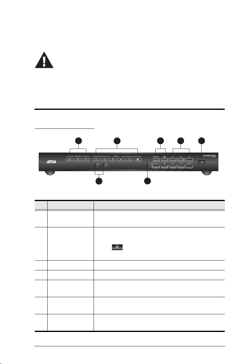
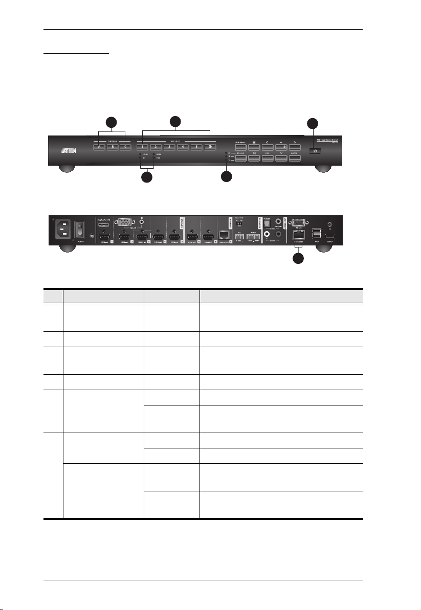
VP2730 Front View
No. Component Description
1 Display Selection
Pushbuttons
2 Source Selection
Pushbuttons
3 Source LEDs Indicate the selected sources for Source (1) and (2).
4 Go Live LEDs Indicate the display that is streamed out.
5 Function
Pushbuttons
6 Navigation
Pushbuttons
7On/Off
Pushbuttons
Press to focus a display. The pushbutton for the
focused display lights amber.
Press to select a source for the focused display. The
pushbutton for the selected source lights green.
Press
Internet.
Press to access multiview, menu, go-live settings,
and mute settings.
Press to navigate and configure settings via the
OSD.
Press to turn on the unit.
to stream in a video source over the
5
16 17
18
1 2
3
11
15
10
12
13
9
4 5 7 8
14
6
Chapter 2. Hardware Setup
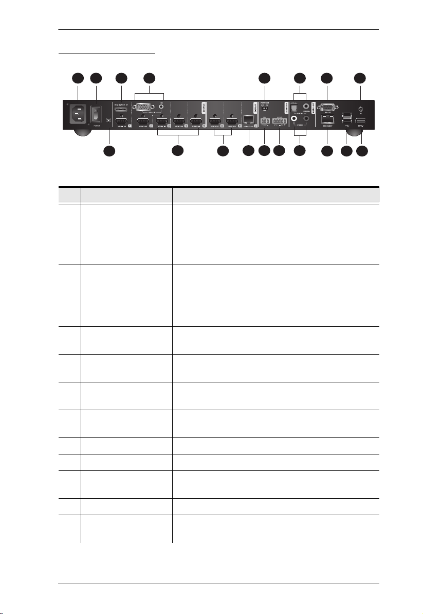
VP2730 Rear View
No. Component Description
1 Source (1) Connects up to two source devices, one
equipped with a DisplayPort, another equipped
with an HDMI port. Users can select which
source to display by pressing the Source
Selection pushbutton on the front panel.
2 Source (2) Connects up to two source devices, one
equipped with a VGA port, another equipped with
an HDMI port. Users can select which source to
display by pressing the Source Selection
pushbutton on the front panel.
3 Source (3), (4), and
(5)
4 HDMI Out Connect to display devices equipped with an
5 HDBaseT Out Connects to a display device equipped with an
6 Phantom Power Enables or disables phantom power supply for a
7 Mic In Connects to a microphone.
8 Balanced Audio In Connects to a balanced analog audio source.
9 Digital Audio Out Connects to a speaker via Optical Audio Out or
10 Stereo Audio Out Connects to a speaker.
11 RS-232 Serial Port Connects to a hardware or software controller to
Connect to HDMI source devices via HDMI
cables.
HDMI port.
HDBaseT port.
condenser microphone.
Coaxial Audio Out port.
transmit serial data.
6

VP2730 User Manual
No. Component Description
12 Ethernet Port Connects to a network switch via an RJ-45 cable
to allow streaming of audio and video data over
IP.
13 USB Type-A Ports
(2.0)
14 USB Type-A Port
(3.0)
Receive up to two USB 2.0 devices as external
storages.
Receives a USB 3.0 device as an external
storage.
15 IR Receiver Port Connects to an IR receiver to receive IR signals
from the IR remote control.
16 Power Socket Receives a power cord to supply power to the
VP2730.
17 Power Switch Enables (ON) or disables (OFF) the power
supply to the VP2730.
18 Grounding Terminal Grounds the VP2730 to prevent damages from
power surge or static electricity.
7
Chapter 2. Hardware Setup
1
2
3
4
5
6
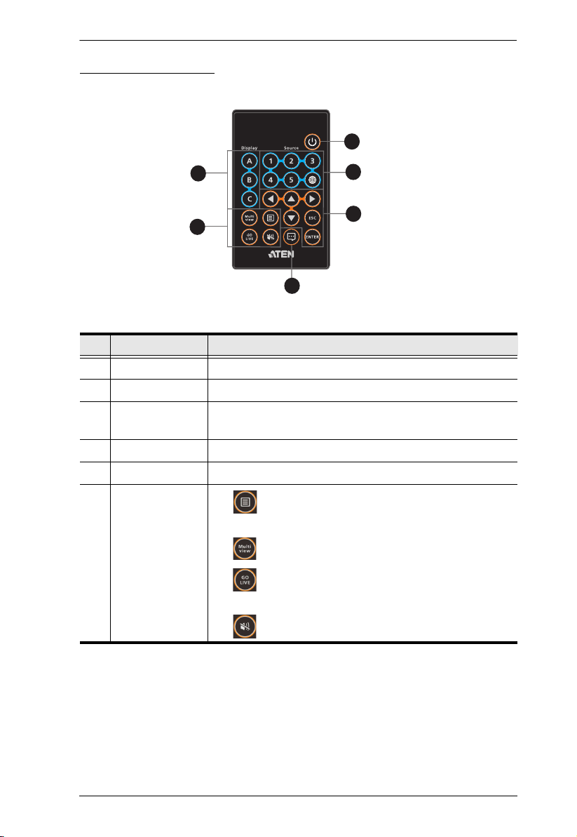
IR Remote Control
No. Buttons Description
1 On/Off Turns the VP2730 on or off.
2 Source Selects sources for connected displays.
3 Navigation Navigates in the OSD, selects or unselects options, or
leaves a current screen in the OSD.
4 Notifications Opens the Notifications panel.
5 Display Focuses the chosen display.
6 Function
: Displays the OSD. Press again to display the
OSD for the next connected display.
: Switches the current display to multiview.
: Streams out the current display out via the
Ethernet.
: Mutes the current display.
8
LED Display
VP2730 Front Panel
VP2730 Rear Panel
5
6
1
3
2
4
You can find the unit’s LEDs as illustrated below. See the table below for details
on LED indication.
No. LED Indication Description
1 Display Pushbuttons Light amber The indicated display device (Display A, B,
2 Source Pushbuttons Light green The indicated source is selected for display.
3 Source LEDs Light green The indicated source (interface) is selected
4 Go Live LEDs Light amber The indicated display is streamed out.
5 Power Lights green The unit is powered and turned to ON.
6ACT
(Left LED)
Link
(Right LED)
VP2730 User Manual
or C) is focused.
for the combo port.
Lights orange The unit is connected to power, but is
currently OFF.
Lights orange Data is being transmitted at 100 Mpbs.
Lights green Data is being transmitted at 1 Gpbs.
Lights green LAN is connected and no data is being
transmitted.
Blinks green LAN is connected and data is being
transmitted.
9
Chapter 2. Hardware Setup
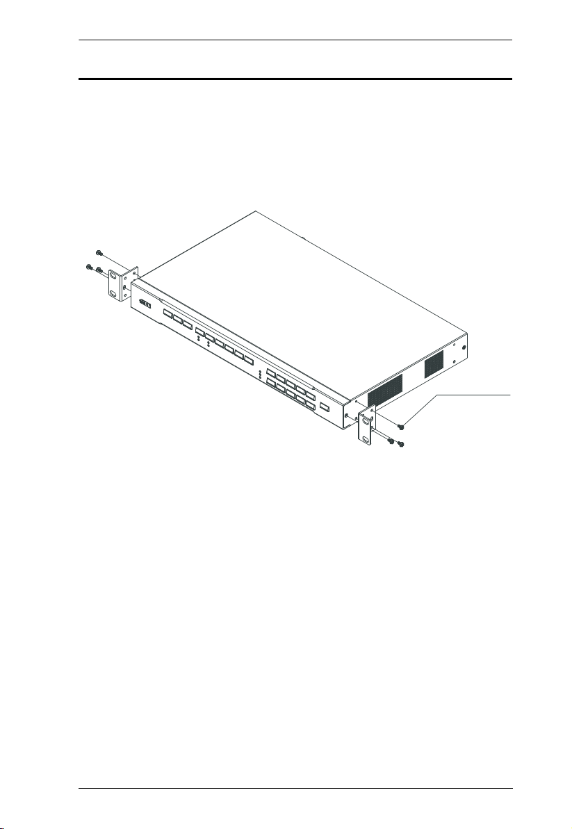
M3 Phillips Hex Head
Rack Mount
The VP2730 can be mounted on a 19” (1U) system rack. To conveniently
access the front-panel pushbuttons for local configuration and operation, mount
the unit at the front of the rack so that the front panel faces outward.
1. Use the 6 M3 Phillips hex head screws supplied with the mounting kit to
secure the rack mounting brackets onto the unit.
2. Position the unit in the front of the rack and align the holes in the mounting
brackets with the holes in the rack.
3. Screw the mounting brackets to the rack.
10
VP2730 User Manual
1
2
3
4
5
6
7
8
A
B
C
Internet/
LAN
Streaming 1 Streaming 2
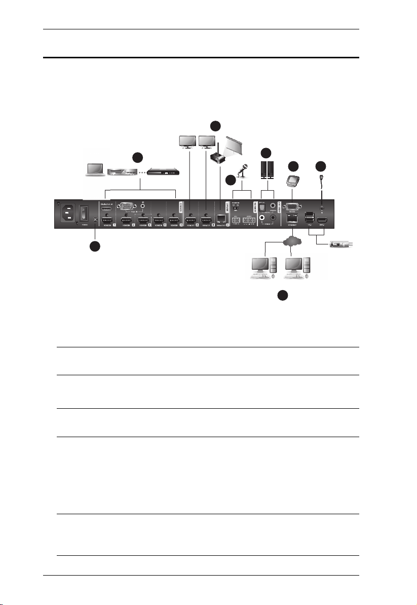
Installation
Follow the steps below to safely install sources, displays, and other equipment
to the VP2730.
1. Use a grounding wire to ground the unit by connecting one end to the
grounding terminal, and the other end to a suitable grounded object.
Note: Do not omit this step. Proper grounding helps prevent damage to the
unit from surges or static electricity.
2. Connect the unit to sources.
Note: Source (1) and (2) can each receive two sources, but can only output
one at a time.
3. Connect the unit to displays.
a) Use HDMI cables to connect HDMI displays to the HDMI out ports.
b) Use a Cat 5e/6/6a cable to connect an HDBaseT display to the
HDBaseT Out port.
Note: Use a Cat 5e/6 cable to transmit signals of 1080p up to 60 m, or a
70 m.
Cat 6a/ATEN 2L-2910 Cat 6a cable to extend the transmission up to
11

Chapter 2. Hardware Setup
4. Connect a microphone to the Mic In port.
Note: If you use a condenser (capacitor) microphone, put the Phantom
Power Switch to ON.
5. Connect a speaker to the Digital Audio Out port (via an amplifier and a
converter) or the Stereo Audio Out port.
6. To configure the unit’s settings via an RS-232 interface, connect a
hardware or software controller to the RS-232 Serial Port.
7. To allow streaming over IP, use an RJ-45 cable to connect the Ethernet port
of the unit to a network switch.
8. Connect the IR receiver to the IR Receiver port for IR remote control.
9. Plug the Power Cord to the power socket, put the power switch to ON, and
then press the On/Off pushbutton.
10. Power on all the connected devices.
12

Chapter 3
Local Operation
Overview
This chapter provides detailed information on the features of the VP2730’s onscreen display (OSD), and how to locally operate the unit using the front-panel
pushbuttons and the IR remote control. You can perform the following tasks with
the OSD:
Switch display sources
Change the display mode, resolution, or aspect ratio settings
Stream out (go live) the current display via network connection
Configure the VP2730’s main system settings
Remotely control another display in the VP2730’s environment (moderator
mode)
Make screen captures
Freeze the screen
Operation Considerations
Make sure to use the IR remote control within the effective range (6 m), and
that there is a clear line-of-sight between the remote control unit and the IR
receiver connected to the VP2730.
The IR remote control and the VP2730’s front panel offer the same
operation capability. Use either method as required.
13
 Loading...