

4 x 2 True 4K Presentation Matrix Switch
VP1420 / VP1421 User Manual
www.aten.com

VP1420 / VP1421 User Manual
EMC Information
FEDERAL COMMUNICATIONS COMMISSION INTERFERENCE
STATEMENT: This equipment has been tested and found to comply with the
limits for a Class A digital device, pursuant to Part 15 of the FCC Rules. These
limits are designed to provide reasonable protection against harmful
interference when the equipment is operated in a commercial environment. This
equipment generates, uses, and can radiate radio frequency energy and, if not
installed and used in accordance with the instruction manual, may cause
harmful interference to radio communications. Operation of this equipment in a
residential area is likely to cause harmful interference in which case the user will
be required to correct the interference at his own expense.
FCC Caution: Any changes or modifications not expressly approved by the
party responsible for compliance could void the user's authority to operate this
equipment.
Warning: Operation of this equipment in a residential environment could cause
radio interference.
This device complies with Part 15 of the FCC Rules. O peration is subject to the
following two conditions:
(1) this device may not cause harmful interference, and
(2) this device must accept any interference received, including interference
that may cause undesired operation.
Suggestion: Shielded twisted pair (STP) cables must be used with the unit to
ensure compliance with FCC & CE standards.
RoHS
This product is RoHS compliant.
ii

VP1420 / VP1421 User Manual
User Information
Online Registration
Be sure to register your product at our online support center:
International http://eservice.aten.com
Telephone Support
For telephone support, call this number:
International 886-2-8692-6959
China 86-400-810-0-810
Japan 81-3-5615-5811
Korea 82-2-467-6789
North America 1-888-999-ATEN ext 4988
1- 949-428-1111
User Notice
All information, documentation, and specifications contained in this manual are
subject to change without prior notification by the manufacturer. The
manufacturer makes no representations or warranties, either expressed or
implied, with respect to the contents hereof and specifically disclaims any
warranties as to merchantability or fitness for any particular purpose. Any of the
manufacturer's software described in this manual is sold or licensed as is.
Should the programs prove defective following their purchase, the buyer (and
not the manufacturer, its distributor, or its dealer), assumes the entire cost of all
necessary servicing, repair and any incidental or consequential damages
resulting from any defect in the software.
The manufacturer of this system is not responsible for any radio and/or TV
interference caused by unauthorized modifications to this device. It is the
responsibility of the user to correct such interference.
The manufacturer is not responsible for any damage incurred in the operation
of this system if the correct operational voltage setting was not selected prior to
operation. PLEASE VERIFY THAT THE VOLTAGE SETTING IS CORRECT
BEFORE USE.
iii

VP1420 / VP1421 User Manual
Package Contents
Make sure that all of the items are present and in good order. If anything is
missing or was damaged in shipping, please contact your dealer for further
assistance.
VP1420
1 VP1420 4 x 2 True 4K Presentation Matrix Switch
1 IR Receiver
1 IR Remote Control
2 3-pole Terminal Blocks
2 5-pole Terminal Blocks
1 Power Adapter
1 User Instructions
VP1421
1 VP1421 4 x 2 True 4K Presentation Matrix Switch with Scaling, DSP, and
HDBaseT-Lite
1 IR Receiver
1 IR Remote Control
4 3-pole Terminal Blocks
2 5-pole Terminal Blocks
1 Power Adapter
1 User Instructions
VPK104
1 VPK104 4-Key Contact Closure Remote Pad
4 4-Pole Terminal Blocks
1 User Instructions
iv

VP1420 / VP1421 User Manual
Table of Contents
EMC Information. . . . . . . . . . . . . . . . . . . . . . . . . . . . . . . . . . . . . . . . . . . . . ii
RoHS . . . . . . . . . . . . . . . . . . . . . . . . . . . . . . . . . . . . . . . . . . . . . . . . . . . . . ii
User Information . . . . . . . . . . . . . . . . . . . . . . . . . . . . . . . . . . . . . . . . . . . . iii
Online Registration . . . . . . . . . . . . . . . . . . . . . . . . . . . . . . . . . . . . . . . .iii
Package Contents . . . . . . . . . . . . . . . . . . . . . . . . . . . . . . . . . . . . . . . . . . .iv
About this Manual . . . . . . . . . . . . . . . . . . . . . . . . . . . . . . . . . . . . . . . . . . vii
Conventions . . . . . . . . . . . . . . . . . . . . . . . . . . . . . . . . . . . . . . . . . . . . . . . viii
Product Information . . . . . . . . . . . . . . . . . . . . . . . . . . . . . . . . . . . . . . . . . viii
1. Introduction
Overview. . . . . . . . . . . . . . . . . . . . . . . . . . . . . . . . . . . . . . . . . . . . . . . . . . . 1
Features . . . . . . . . . . . . . . . . . . . . . . . . . . . . . . . . . . . . . . . . . . . . . . . . . . . 2
VP1420 . . . . . . . . . . . . . . . . . . . . . . . . . . . . . . . . . . . . . . . . . . . . . . . . . 2
VP1421 . . . . . . . . . . . . . . . . . . . . . . . . . . . . . . . . . . . . . . . . . . . . . . . . 4
Planning the Installation . . . . . . . . . . . . . . . . . . . . . . . . . . . . . . . . . . . . . . . 6
Required Equipment . . . . . . . . . . . . . . . . . . . . . . . . . . . . . . . . . . . . . . . 6
VP1420 . . . . . . . . . . . . . . . . . . . . . . . . . . . . . . . . . . . . . . . . . . . . . . 6
VP1421 . . . . . . . . . . . . . . . . . . . . . . . . . . . . . . . . . . . . . . . . . . . . . . 6
Optional Equipment . . . . . . . . . . . . . . . . . . . . . . . . . . . . . . . . . . . . . . . 7
VP1420 . . . . . . . . . . . . . . . . . . . . . . . . . . . . . . . . . . . . . . . . . . . . . . 7
VP1421 . . . . . . . . . . . . . . . . . . . . . . . . . . . . . . . . . . . . . . . . . . . . . . 7
2. Hardware Setup
Hardware Overview . . . . . . . . . . . . . . . . . . . . . . . . . . . . . . . . . . . . . . . . . . 9
VP1420 . . . . . . . . . . . . . . . . . . . . . . . . . . . . . . . . . . . . . . . . . . . . . . . . 9
Front View . . . . . . . . . . . . . . . . . . . . . . . . . . . . . . . . . . . . . . . . . . . 9
Rear View . . . . . . . . . . . . . . . . . . . . . . . . . . . . . . . . . . . . . . . . . . . 10
VP1421 . . . . . . . . . . . . . . . . . . . . . . . . . . . . . . . . . . . . . . . . . . . . . . . 11
Front View . . . . . . . . . . . . . . . . . . . . . . . . . . . . . . . . . . . . . . . . . . 11
Rear View . . . . . . . . . . . . . . . . . . . . . . . . . . . . . . . . . . . . . . . . . . . 12
IR Remote Control . . . . . . . . . . . . . . . . . . . . . . . . . . . . . . . . . . . . . . . 14
VPK104 . . . . . . . . . . . . . . . . . . . . . . . . . . . . . . . . . . . . . . . . . . . . . . . 15
Front View . . . . . . . . . . . . . . . . . . . . . . . . . . . . . . . . . . . . . . . . . . 15
Rear View . . . . . . . . . . . . . . . . . . . . . . . . . . . . . . . . . . . . . . . . . . . 16
Side View . . . . . . . . . . . . . . . . . . . . . . . . . . . . . . . . . . . . . . . . . . . 16
Mounting . . . . . . . . . . . . . . . . . . . . . . . . . . . . . . . . . . . . . . . . . . . . . . . . . 17
Rack Mount . . . . . . . . . . . . . . . . . . . . . . . . . . . . . . . . . . . . . . . . . . . . 17
Under Desk Mount . . . . . . . . . . . . . . . . . . . . . . . . . . . . . . . . . . . . . . . 18
Installation . . . . . . . . . . . . . . . . . . . . . . . . . . . . . . . . . . . . . . . . . . . . . . . . 19
VP1420 . . . . . . . . . . . . . . . . . . . . . . . . . . . . . . . . . . . . . . . . . . . . . . . 19
VP1421 . . . . . . . . . . . . . . . . . . . . . . . . . . . . . . . . . . . . . . . . . . . . . . . 21
VPK104 . . . . . . . . . . . . . . . . . . . . . . . . . . . . . . . . . . . . . . . . . . . . . . . 23
v

VP1420 / VP1421 User Manual
3. Local Operation
Overview . . . . . . . . . . . . . . . . . . . . . . . . . . . . . . . . . . . . . . . . . . . . . . . . . .25
Operation Considerations . . . . . . . . . . . . . . . . . . . . . . . . . . . . . . . . . .25
Switching Sources. . . . . . . . . . . . . . . . . . . . . . . . . . . . . . . . . . . . . . . . . . .25
Display Mode . . . . . . . . . . . . . . . . . . . . . . . . . . . . . . . . . . . . . . . . . . . . . .26
Understanding Display Mode . . . . . . . . . . . . . . . . . . . . . . . . . . . . . . .26
Configuration. . . . . . . . . . . . . . . . . . . . . . . . . . . . . . . . . . . . . . . . . . . .26
Audio Settings . . . . . . . . . . . . . . . . . . . . . . . . . . . . . . . . . . . . . . . . . . . . .27
Panel Lock . . . . . . . . . . . . . . . . . . . . . . . . . . . . . . . . . . . . . . . . . . . . . . . .28
Power LED Indication . . . . . . . . . . . . . . . . . . . . . . . . . . . . . . . . . . . . . . . . 29
4. Remote Operation
Overview . . . . . . . . . . . . . . . . . . . . . . . . . . . . . . . . . . . . . . . . . . . . . . . . . .31
Default Network and Login Settings . . . . . . . . . . . . . . . . . . . . . . . . . .31
Supported Web Browsers . . . . . . . . . . . . . . . . . . . . . . . . . . . . . . . . . 32
Logging In the Web Console . . . . . . . . . . . . . . . . . . . . . . . . . . . . . . . 33
The Main Screen . . . . . . . . . . . . . . . . . . . . . . . . . . . . . . . . . . . . . . . .34
General Settings . . . . . . . . . . . . . . . . . . . . . . . . . . . . . . . . . . . . . . . . . . . 35
Audio & Video Settings . . . . . . . . . . . . . . . . . . . . . . . . . . . . . . . . . . . . . . 37
Audio Control . . . . . . . . . . . . . . . . . . . . . . . . . . . . . . . . . . . . . . . . . . .37
Audio Output . . . . . . . . . . . . . . . . . . . . . . . . . . . . . . . . . . . . . . . . . 38
Audio Input (VP1420) . . . . . . . . . . . . . . . . . . . . . . . . . . . . . . . . . . 38
Audio Input (VP1421) . . . . . . . . . . . . . . . . . . . . . . . . . . . . . . . . . . 38
Apply vs. Auto Apply . . . . . . . . . . . . . . . . . . . . . . . . . . . . . . . . . . . 39
Video Control . . . . . . . . . . . . . . . . . . . . . . . . . . . . . . . . . . . . . . . . . . .40
Apply vs. Auto Apply . . . . . . . . . . . . . . . . . . . . . . . . . . . . . . . . . . . 41
System Settings . . . . . . . . . . . . . . . . . . . . . . . . . . . . . . . . . . . . . . . . . . . . 42
Maintenance . . . . . . . . . . . . . . . . . . . . . . . . . . . . . . . . . . . . . . . . . . . . 42
Upgrading the System Firmware . . . . . . . . . . . . . . . . . . . . . . . . .42
Backing Up System Settings . . . . . . . . . . . . . . . . . . . . . . . . . . . . .43
Restoring System Settings . . . . . . . . . . . . . . . . . . . . . . . . . . . . . . 43
Reseting the Default Settings . . . . . . . . . . . . . . . . . . . . . . . . . . . .43
Network Settings . . . . . . . . . . . . . . . . . . . . . . . . . . . . . . . . . . . . . . . . 44
IP Settings . . . . . . . . . . . . . . . . . . . . . . . . . . . . . . . . . . . . . . . . . .44
Browser . . . . . . . . . . . . . . . . . . . . . . . . . . . . . . . . . . . . . . . . . . . . .44
5. CLI Commands
Overview . . . . . . . . . . . . . . . . . . . . . . . . . . . . . . . . . . . . . . . . . . . . . . . . . .45
Setup. . . . . . . . . . . . . . . . . . . . . . . . . . . . . . . . . . . . . . . . . . . . . . . . . . . . .45
Command Syntax . . . . . . . . . . . . . . . . . . . . . . . . . . . . . . . . . . . . . . . . . . . 46
Command List . . . . . . . . . . . . . . . . . . . . . . . . . . . . . . . . . . . . . . . . . . . . .47
Port Numbers . . . . . . . . . . . . . . . . . . . . . . . . . . . . . . . . . . . . . . . .47
cec . . . . . . . . . . . . . . . . . . . . . . . . . . . . . . . . . . . . . . . . . . . . . . . . . 47
displaymode. . . . . . . . . . . . . . . . . . . . . . . . . . . . . . . . . . . . . . . . . .48
echo . . . . . . . . . . . . . . . . . . . . . . . . . . . . . . . . . . . . . . . . . . . . . . . .48
vi

VP1420 / VP1421 User Manual
edid . . . . . . . . . . . . . . . . . . . . . . . . . . . . . . . . . . . . . . . . . . . . . . . . 48
mute . . . . . . . . . . . . . . . . . . . . . . . . . . . . . . . . . . . . . . . . . . . . . . . 49
power. . . . . . . . . . . . . . . . . . . . . . . . . . . . . . . . . . . . . . . . . . . . . . . 49
read . . . . . . . . . . . . . . . . . . . . . . . . . . . . . . . . . . . . . . . . . . . . . . . . 50
reset . . . . . . . . . . . . . . . . . . . . . . . . . . . . . . . . . . . . . . . . . . . . . . . 50
sw . . . . . . . . . . . . . . . . . . . . . . . . . . . . . . . . . . . . . . . . . . . . . . . . . 50
swmode . . . . . . . . . . . . . . . . . . . . . . . . . . . . . . . . . . . . . . . . . . . . . 50
volume. . . . . . . . . . . . . . . . . . . . . . . . . . . . . . . . . . . . . . . . . . . . . . 51
Appendix
Safety Instructions . . . . . . . . . . . . . . . . . . . . . . . . . . . . . . . . . . . . . . . . . . 53
General . . . . . . . . . . . . . . . . . . . . . . . . . . . . . . . . . . . . . . . . . . . . . . . . 53
Rack Mounting . . . . . . . . . . . . . . . . . . . . . . . . . . . . . . . . . . . . . . . . . . 55
Technical Support . . . . . . . . . . . . . . . . . . . . . . . . . . . . . . . . . . . . . . . . . . 56
International . . . . . . . . . . . . . . . . . . . . . . . . . . . . . . . . . . . . . . . . . . . . 56
Specifications . . . . . . . . . . . . . . . . . . . . . . . . . . . . . . . . . . . . . . . . . . . . . . 57
VP1420 . . . . . . . . . . . . . . . . . . . . . . . . . . . . . . . . . . . . . . . . . . . . . . . 57
VP1421 Specifications . . . . . . . . . . . . . . . . . . . . . . . . . . . . . . . . . . . . 59
Limited Warranty . . . . . . . . . . . . . . . . . . . . . . . . . . . . . . . . . . . . . . . . . . . 62
vii

VP1420 / VP1421 User Manual
About this Manual
This user manual is provided to help you get the most from the 4 x 2 True 4K
Presentation Matrix Switch and Remote Pad. It covers all aspects of installation,
configuration, and operation for the following models:
Device Type Device Model Device Name
VP1420 4 x 2 True 4K Presentation Matrix Switch
Presentation Switch
Remote Pad VPK104 4-Key Contact Closure Remote Pad
Chapter 1, Introduction introduces you to the VP1420 / VP1421. Its purpose,
features, benefits, and installation considerations are described.
Chapter 2, Hardware Setup introduces the panel components of the 4 x 2 True
4K Presentation Matrix Switch and the IR Remote Control, and details the steps
to quickly and safely install the VP1420 / VP1421.
Chapter 3, Local Operation provides information on how to locally operate and
access the system settings via the panel pushbuttons and IR remote control.
VP1421 4 x 2 True 4K Presentation Matrix Switch with
Scaling, DSP, and HDBaseT-Lite
Chapter 4, Remote Operation provides details on remote management and
control tasks via the system web interface.
Appendix provides a list of safety instructions and precautions, contact
information for ATEN technical support, product specifications, and other
technical information.
Note:
Read this manual thoroughly and follow the installation and operation
procedures carefully to prevent any damage to the unit or any connected
devices.
ATEN regularly updates its product documentation for new features and
fixes. For an up-to-date VP1420 / VP1421 documentation, visit
http://www.aten.com/global/en/
viii

Conventions
This manual uses the following conventions:
Monospaced Indicates text that you should key in.
[ ] Indicates keys you should press. For example, [Enter] means to
press the Enter key. If keys need to be chorded, they appear
together in the same bracket with a plus sign between them:
[Ctrl+Alt].
1. Numbered lists represent procedures with sequential steps.
♦ Bullet lists provide information, but do not involve sequential steps.
→ Indicates selecting the option (on a menu or dialog box, for
example), that comes next. For example, Start
open the Start menu, and then select Run.
Indicates critical information.
Product Information
VP1420 / VP1421 User Manual
→
Run means to
For information about all ATEN products and how they can help you connect
without limits, visit ATEN on the Web or contact an ATEN Authorized Reseller.
Visit ATEN on the Web for a list of locations and telephone numbers:
International http://www.aten.com
North America http://www.aten-usa.com
ix

VP1420 / VP1421 User Manual
This Page Intentionally Left Blank
x

Chapter 1
Introduction
Overview
The ATEN VP1420/VP1421 is a multi-in-one presentation switch that integrates
a video matrix switch, True 4K scaler, analog-to-digital converter, audio
processor (VP1420), HDBaseT Extender (VP1421), and audio DSP (VP1421)
into one compact device. With the four analog/digital inputs to 2 HDMI True 4K
outputs (VP1420) / 1 HDMI & 1 HDBaseT outputs (VP1421), the VP1420/
VP1421 is designed to boost the efficiency and impact of professional
presentations.
With its versatile control via the front panel, IR remote controller, RS-232 serial
commands, and web GUI, the VP1420/VP1421 reduces not only system device
count, but also lowers operation complexity. The VP1420/VP1421 is suitable for
all meeting space and education environments, such as huddle rooms,
classrooms, training rooms, or any other presentation setting, such as exhibition
galleries or hotels.
1

Chapter 1. Introduction
Features
VP1420
Analog/Digital AV Matrix
Supports 4 multi-format inputs – 3 HDMI and 1 VGA inputs
2 HDMI outputs
Audio embedding – stereo audio can be embedded into HDMI output or
separated to stereo line out
Audio de-embedding – HDMI audio can be extracted to stereo line out
Auto switching – automatically detects and switches to a new source as
soon as it is connected
High-definition Video with Optimum Output
Superior video quality – True 4K resolutions up to 4096 x 2160@60Hz
(4:4:4)(HDMI)
Supports 4K HDR
Scaler – supports video upscaling to 4K for display A and downscaling to
1080p for display B
EDID Export™ – automatically selects the optimum EDID settings for
smooth power-up, high-quality display, and the best video resolution across
connected devices
HDMI 2.0 (3D, Deep Color, 4K); HDCP 2.2 compliant
Versatile, Streamlined Operation
Multiple Control Options – flexible control via the front panel, IR remote
control, RS-232, and web-based GUI through Ethernet
Supports standby mode for power saving and fast waking up
Consumer Electronics Control (CEC) support
Built-in contact in and LED out ports for keypad control using the ATEN
VPK104 Contact Closure Remote Pad
2
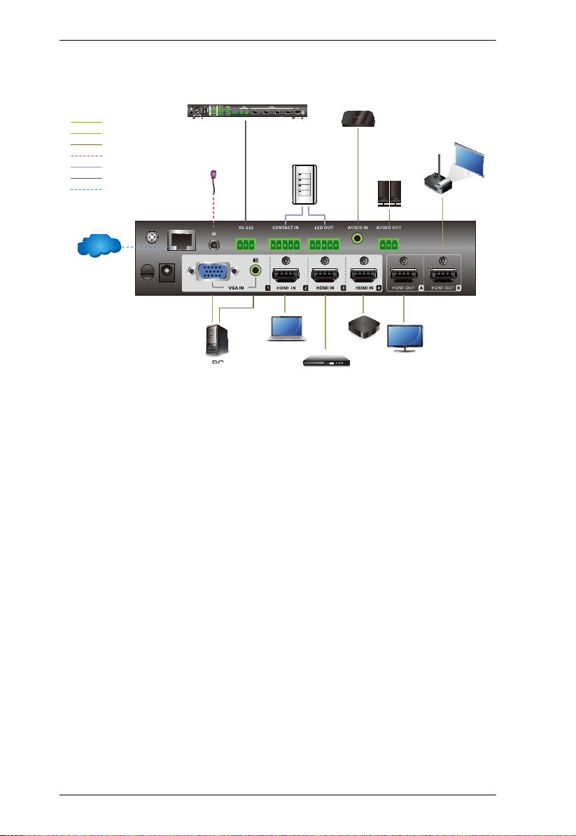
VP1420 / VP1421
Internet/
LAN
MMM
A
B
I/O
IR
Network
RS-232
Audio
HDMI
VGA
ATEN Control Box
IR Recevier
PC
Laptop
TV Box
Blue-ray Player
VPK104 Contact Closure
Remote Pad
Media Player
Active
Speaker
User Manual
3

Chapter 1. Introduction
VP1421
Analog/Digital AV Matrix
Supports 4 multi-format inputs – 2 HDMI, 1 HDBaseT, and 1 VGA inputs
1 HDMI and 1 HDBaseT outputs
Audio embedding – stereo audio can be embedded into the display output
or separated to stereo or optical audio outputs
Audio de-embedding – HDMI/HDBaseT audio can be extracted to stereo
audio output
Built-in audio DSP – supports microphone input with selectable 48V
Phantom Power and allows microphone input to be mixed with program
audio and embedded into display output
Automatically reduces program audio when a microphone signal is
detected
Auto switching – automatically detects and switches to a new source as
soon as it is connected for time-saving and convenience
High-definition Video with Optimum Output
Superior video quality – Up to 4096 x 2160@60Hz (4:4:4) (HDMI) / Up to
4096 x 2160@60Hz (4:2:0) (HDBaseT)
Supports HDR
Scaler – supports video upscaling to 4K for display A and downscaling to
1080p for display B
EDID Export™ – automatically selects the optimum EDID settings for
smooth power-up, high-quality display, and the best video resolution across
connected devices
HDMI 2.0 (3D, Deep Color, 4K); HDCP 2.2 compliant
Versatile, Streamlined Operation
Multiple Control Options – flexible control via the front panel, IR remote
control, RS-232, and web-based GUI through Ethernet
Bi-directional RS-232 and IR channel – allows AV device control over
HDBaseT connection without additional cabling
Supports standby mode for power saving and fast waking up
Consumer Electronics Control (CEC) support
4

VP1420 / VP1421
Internet/
LAN
A
B
I/O
IR
Network
RS-232
Audio
HDMI
HDBaseT
VGA
ATEN Control Box
Microphone
IR Recevier
PC
Laptop
TV Box
Blue-ray Player
Interface Box
Media Player
VE802R
VE802T
Rear View
Front View
Active
Speaker
Built-in contact in and LED out ports for keypad control using the ATEN
User Manual
VPK104 Contact Closure Remote Pad
Extended Transmission over One Cable
Long-distance transmission – transmit digital AV signal, bi-directional
RS-232, and IR control signals up to 140 m via Cat 6/6a or ATEN 2L-2910
Cat 6 cables
Note: This is achieved using the HDBaseT In and HDBaseT Out ports on
the VP1421, each extending the transmission up to 70 m.
Power over HDBaseT (PoH) – remote powering over existing
communication cable with selectable powering device.
5

Chapter 1. Introduction
Planning the Installation
Required Equipment
Prepare the following equipment before installing the VP1420 / VP1421.
VP1420
Up to 3 input devices equipped with HDMI and 1 input device equipped with
a VGA port
Up to 2 display devices each equipped with an HDMI port
VP1421
Up to 2 input devices equipped with HDMI ports, 1 input device equipped
with an HDBaseT port and 1 device equipped with a VGA port
Up to 2 display devices, one equipped with an HDMI port and the other
equipped with an HDBaseT port
6

VP1420 / VP1421
User Manual
Optional Equipment
Prepare the following equipment as required.
VP1420
1 media player
1 Active Speaker
1 Ethernet cable to connect the VP1421 to a network switch for remote
management via the web console
1 RS-232 serial controller or ATEN Control Box for RS-232 serial control
1 ATEN VPK104 Contact Closure Remote Pad for convenient operation
Mounting kits:
Rack Mount Kit
Under Desk Mount Kit
VP1421
1 microphone
1 media player
1 Active Speaker
1 video transmitter and 1 receiver equipped with HDBaseT ports for signal
extension
1 Ethernet cable to connect the VP1421 to a network switch for remote
management via the web console
1 RS-232 serial controller or ATEN Control Box for RS-232 serial control
1 ATEN VPK104 Contact Closure Remote Pad for convenient operation
Mounting kits:
Rack Mount Kit
Under Desk Mount Kit
7

Chapter 1. Introduction
This Page Intentionally Left Blank
8
Chapter 2
1. Please review the safety information regarding the placement of this
device in Safety Instructions, page 53.
2. Do not power on the VP1420 / VP1421 until all the necessary hardware
is connected.
1
2
3
4
5
Hardware Setup
Hardware Overview
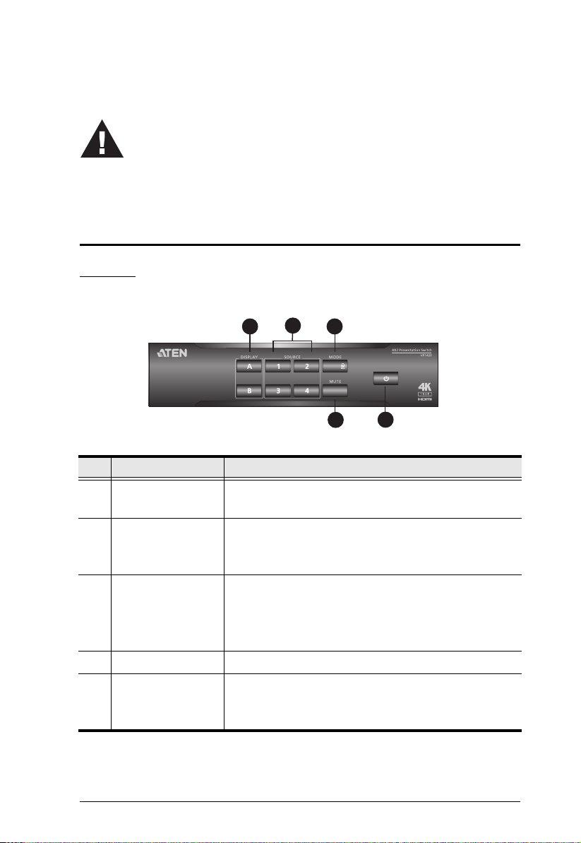
VP1420
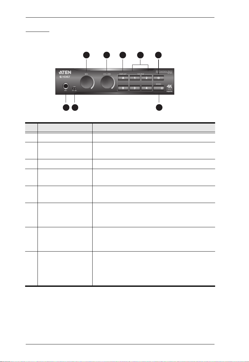
Front View
No. Component Description
1 Display Selection
Pushbuttons
2 Source Selection
Pushbuttons
3 Mode Pushbutton
4 Mute Pushbutton Press to mute all displays and speakers.
5 Power Pushbutton Used to power on/off the VP1420, or enable/disable
Press to focus a display. The pushbutton for the
focused display lights orange.
Press to select a source for the focused display.
The pushbutton for the selected source lights
green.
Press the pushbutton once to show the current
mode setting.
Press the pushbutton twice to switch between
the Matrix mode and the Mirror mode.
the standby mode. For details, see Power LED
Indication, page 29.
9
Chapter 2. Hardware Setup
4
1
2
3
7
8
9
10 11 12 13
5
6
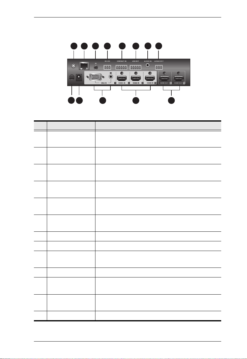
Rear View
No. Component Description
1 Grounding
Terminal
2 Ethernet Port Connects to a network switch via an Ethernet cable
3 IR Receiver Port Connects to an IR receiver to receive IR signals
4 RS-232 Serial
Port
5 Contact In Connects to the Contact Out terminal of a contact
6 LED Out Connects to the LED In terminal of a contact
7 Audio In Receives an audio source.
8 Audio Out Connects to an active speaker.
9 Cable Tie Slot Reserved for a cable tie to hold the power adapter
10 Power Jack Receives a power adapter of the VP1420.
11 Source (1) Connects to a VGA source and a stereo audio
12 Source (2), (3), (4) Each connects to an HDMI source device via an
13 HDMI Out Each connects to an HDMI-enabled display device.
Grounds the VP1420 to prevent damages from
power surge or static electricity.
to allow remote operation via the web console.
from the IR remote control.
Connects to a hardware or software controller to
transmit serial data.
closure interface.
closure interface
in place.
source.
HDMI cable.
10
VP1420 / VP1421 User Manual
543
6
7
1 2
8
VP1421
Front View
No. Component Description
1 MIC In Port Connects to a microphone.
2 Phantom Power
Switch
3 MIC Volume Control Use the knob to adjust the microphone volume.
4 Overall Volume
Control
5 Display Selection
Pushbuttons
6 Source Selection
Pushbuttons
7 Power Pushbutton Used to power on/off the VP1420, or enable/
8 Mode Pushbutton
Enables or disables the supply of phantom power
to a condenser microphone.
Use the knob to adjust the volume of all audio
outputs.
Press a pushbutton to focus a display. The
pushbutton for the focused display lights orange.
Press a pushbutton to select a source for the
focused display. The pushbutton for the selected
source lights green.
disable the standby mode. For details, see Power
LED Indication, page 29.
To show the current display mode, press the
pushbutton once
To switch between the Matrix mode and the
Mirror mode, press the pushbutton twice.
11
Chapter 2. Hardware Setup
4
1
2
3
7
8
9
10 11 12 13 14 15 16
5
6
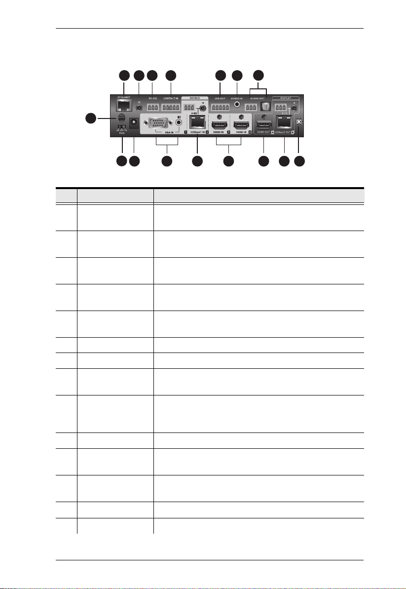
Rear View
No. Component Description
1 Ethernet Port Connects to a network switch via an Ethernet cable
to allow remote operation via the web console.
2 IR Receiver Port Connects to an IR receiver to receive IR signals
from the IR remote control.
3 RS-232 Serial
Port
4 Contact In Connects to the Contact Out terminal of a contact
5 LED Out Connects to the LED In terminal of a contact closure
6 Audio In Port Receives an audio source.
7 Audio Out Ports Connects to an active speaker.
8 Cable Tie Slot Reserved for a cable tie to hold the power adapter in
9 PoH Control
Switch
10 Power Jack Receives a power adapter of the VP1421.
11 Source (1) Connects to a VGA source and a stereo audio
12 Source (2) Connects to a source device at a distance via a Tx
13 Source (3), (4) Connect to HDMI source devices via HDMI cables.
14 Output/Display A Connects to an HDMI-enabled display device.
Connects to a hardware or software controller to
transmit serial data.
closure interface.
interface
place.
Enables the transmission of power along with data
signals to either the Tx or Rx connected to the
VP1421 over an Ethernet cable.
source.
device equipped with an HDBaseT port
12
 Loading...