

Aten VE157, VE607, VE807 User Manual
VGA/DVI/HDMI Audio Cat 5 Extender with MK Wall Plate
VE157 / VE607 / VE807
User Manual
www.aten.com
VE157 / VE607 / VE807 User Manual
EMC Information
FEDERAL COMMUNICATIONS COMMISSION INTERFERENCE STATEMENT:
This equipment has been tested and found to comply with the limits for a Class A digital
device, pursuant to Part 15 of the FCC Rules. These limits are designed to provide
reasonable protection against harmful interference when the equipment is operated in a
commercial environment. This equipment generates, uses, and can radiate radio
frequency energy and, if not installed and used in accordance with the instruction
manual, may cause harmful interference to radio communications. Operation of this
equipment in a residential area is likely to cause harmful interference in which case the
user will be required to correct the interference at his own expense.
This device complies with Part 15 of the FCC Rules. Operation is subject to the
following two conditions: (1) this device may not cause harmful interference, and (2)
this device must accept any interference received, including interference that may cause
undesired operation.
FCC Caution: Any changes or modifications not expressly approved by the party
responsible for compliance could void the user's authority to operate this equipment.
Warning: Operation of this equipment in a residential environment could cause radio
interference.
Suggestion: Shielded twisted pair (STP) cables must be used with the unit to ensure
compliance with FCC & CE standards.
Achtung: Der Gebrauch dieses Geräts in Wohnumgebung kann Funkstörungen
verursachen.
KCC Statement
RoHS
This product is RoHS compliant.
ii
VE157 / VE607 / VE807 User Manual
User Information
Online Registration
Be sure to register your product at our online support center:
International http://eservice.aten.com
Telephone Support
For telephone support, call this number:
International 886-2-8692-6959
China 86-400-810-0-810
Japan 81-3-5615-5811
Korea 82-2-467-6789
North America 1-888-999-ATEN ext 4988
1- 949-428-1111
User Notice
All information, documentation, and specifications contained in this manual
are subject to change without prior notification by the manufacturer. The
manufacturer makes no representations or warranties, either expressed or
implied, with respect to the contents hereof and specifically disclaims any
warranties as to merchantability or fitness for any particular purpose. Any of
the manufacturer's software described in this manual is sold or licensed as is.
Should the programs prove defective following their purchase, the buyer (and
not the manufacturer, its distributor, or its dealer), assumes the entire cost of all
necessary servicing, repair and any incidental or consequential damages
resulting from any defect in the software.
The manufacturer of this system is not responsible for any radio and/or TV
interference caused by unauthorized modifications to this device. It is the
responsibility of the user to correct such interference.
The manufacturer is not responsible for any damage incurred in the operation
of this system if the correct operational voltage setting was not selected prior
to operation. PLEASE VERIFY THAT THE VOLTAGE SETTING IS
CORRECT BEFORE USE.
iii

VE157 / VE607 / VE807 User Manual
Package Contents
The VGA/DVI/HDMI Audio Cat 5 Extender with MK Wall Plate package
contains the following items:
1 VE157T / VE607T / VE807T VGA/DVI/HDMI Audio Cat 5 Extender
with MK Wall Plate
1 VE157R / VE607R / VE807R VGA/DVI/HDMI Audio Cat 5 Extender
with MK Wall Plate
1 Terminal Block Connector
1 Power Adapter
2 MK type Wall Plate Covers
8 Screw Covers
1 Screw kit
1 User Instructions*
Check to make sure that all the components are present and that nothing got
damaged in shipping. If you encounter a problem, contact your dealer.
Read this manual thoroughly and follow the installation and operation
procedures carefully to prevent any damage to the unit, and/or any of the
devices connected to it.
* Features may have been added to the VE157 / VE607 / VE807 since this
manual was published. Please visit our website to download the most up-todate version.
© Copyright 2020 ATEN® International Co., Ltd.
ATEN and the ATEN logo are registered trademarks of ATEN International Co., Ltd. All rights reserved.
All other brand names and trademarks are the registered property of their respective owners.
iv
Manual Date: 2020-7-28

VE157 / VE607 / VE807 User Manual
Contents
EMC Information . . . . . . . . . . . . . . . . . . . . . . . . . . . . . . . . . . . . . . . . . . . . . ii
RoHS. . . . . . . . . . . . . . . . . . . . . . . . . . . . . . . . . . . . . . . . . . . . . . . . . . . . . . ii
User Information . . . . . . . . . . . . . . . . . . . . . . . . . . . . . . . . . . . . . . . . . . . . .iii
Online Registration . . . . . . . . . . . . . . . . . . . . . . . . . . . . . . . . . . . . . . . .iii
Telephone Support . . . . . . . . . . . . . . . . . . . . . . . . . . . . . . . . . . . . . . . .iii
User Notice . . . . . . . . . . . . . . . . . . . . . . . . . . . . . . . . . . . . . . . . . . . . . .iii
Package Contents. . . . . . . . . . . . . . . . . . . . . . . . . . . . . . . . . . . . . . . . . . . iv
About this Manual . . . . . . . . . . . . . . . . . . . . . . . . . . . . . . . . . . . . . . . . . . . vi
Conventions . . . . . . . . . . . . . . . . . . . . . . . . . . . . . . . . . . . . . . . . . . . . . . . vii
Product Information. . . . . . . . . . . . . . . . . . . . . . . . . . . . . . . . . . . . . . . . . . vii
1. Introduction
Overview . . . . . . . . . . . . . . . . . . . . . . . . . . . . . . . . . . . . . . . . . . . . . . . . . . .1
Features . . . . . . . . . . . . . . . . . . . . . . . . . . . . . . . . . . . . . . . . . . . . . . . . . . . 2
Requirements . . . . . . . . . . . . . . . . . . . . . . . . . . . . . . . . . . . . . . . . . . . . . . . 3
Console . . . . . . . . . . . . . . . . . . . . . . . . . . . . . . . . . . . . . . . . . . . . . . . . . 3
Computer. . . . . . . . . . . . . . . . . . . . . . . . . . . . . . . . . . . . . . . . . . . . . . . . 3
Cables . . . . . . . . . . . . . . . . . . . . . . . . . . . . . . . . . . . . . . . . . . . . . . . . . . 3
Components . . . . . . . . . . . . . . . . . . . . . . . . . . . . . . . . . . . . . . . . . . . . . . . . 4
Front View (Transmitter) . . . . . . . . . . . . . . . . . . . . . . . . . . . . . . . . . . . .4
Front View (Receiver) . . . . . . . . . . . . . . . . . . . . . . . . . . . . . . . . . . . . . .4
Rear View (Transmitter / Receiver) . . . . . . . . . . . . . . . . . . . . . . . . . . . . 5
2. Hardware Setup
Overview . . . . . . . . . . . . . . . . . . . . . . . . . . . . . . . . . . . . . . . . . . . . . . . . . . .7
Wall Plate Dimensions. . . . . . . . . . . . . . . . . . . . . . . . . . . . . . . . . . .7
How to Supply Power . . . . . . . . . . . . . . . . . . . . . . . . . . . . . . . . . . . . . .8
Wall Mounting . . . . . . . . . . . . . . . . . . . . . . . . . . . . . . . . . . . . . . . . . . . 10
Hardware Installation . . . . . . . . . . . . . . . . . . . . . . . . . . . . . . . . . . . . . . . . 11
3. Basic Operation
Overview . . . . . . . . . . . . . . . . . . . . . . . . . . . . . . . . . . . . . . . . . . . . . . . . . .13
Picture Adjustment . . . . . . . . . . . . . . . . . . . . . . . . . . . . . . . . . . . . . . . . . . 13
Appendix
Safety Instructions. . . . . . . . . . . . . . . . . . . . . . . . . . . . . . . . . . . . . . . . . . . 15
General . . . . . . . . . . . . . . . . . . . . . . . . . . . . . . . . . . . . . . . . . . . . . . . . 15
Technical Support . . . . . . . . . . . . . . . . . . . . . . . . . . . . . . . . . . . . . . . . . . .17
International. . . . . . . . . . . . . . . . . . . . . . . . . . . . . . . . . . . . . . . . . . . . . 17
North America . . . . . . . . . . . . . . . . . . . . . . . . . . . . . . . . . . . . . . . . . . . 17
Supported ATEN Products . . . . . . . . . . . . . . . . . . . . . . . . . . . . . . . . . . . .18
Specifications . . . . . . . . . . . . . . . . . . . . . . . . . . . . . . . . . . . . . . . . . . . . . .19
Limited Warranty. . . . . . . . . . . . . . . . . . . . . . . . . . . . . . . . . . . . . . . . . . . . 41
v

VE157 / VE607 / VE807 User Manual
About this Manual
This User Manual is provided to help you get the most from your system. It
covers all aspects of installation, configuration and operation. An overview of
the information found in the manual is provided below.
Chapter 1, Introduction, introduces you to the VE157 / VE607 / VE807
system. Its purpose, features and benefits are presented, and its front and back
panel components are described.
Chapter 2, Hardware Setup, describes how to set up your installation. All
necessary steps to prepare for operation are provided.
Chapter 3, Basic Operation, describes how to adjust the picture quality.
An Appendix, provides specifications and other technical information
regarding the VE157 / VE607 / VE807.
vi
Conventions
This manual uses the following conventions:
Monospaced Indicates text that you should key in.
[ ] Indicates keys you should press. For example, [Enter] means to
press the Enter key. If keys need to be chorded, they appear
together in the same bracket with a plus sign between them:
[Ctrl+Alt].
1. Numbered lists represent procedures with sequential steps.
♦ Bullet lists provide information, but do not involve sequential steps.
→ Indicates selecting the option (on a menu or dialog box, for
example), that comes next. For example, Start
open the Start menu, and then select Run.
Indicates critical information.
Product Information
VE157 / VE607 / VE807 User Manual
→
Run means to
For information about all ATEN products and how they can help you connect
without limits, visit ATEN on the Web or contact an ATEN Authorized
Reseller. Visit ATEN on the Web for a list of locati ons and telephone numbers:
International http://www.aten.com
North America http://www.aten-usa.com
vii

VE157 / VE607 / VE807 User Manual
This Page Intentionally Left Blank
viii

Chapter 1
Introduction
Overview
The VGA/DVI/HDMI Audio Cat 5 Extender with MK Wall Plate extends
VGA/DVI/HDMI and audio signals up to 150 m (for VE157) / 60 m (for
VE607/VE807) using Cat 5e cables. It supports popular wide screen formats
and ensures excellent video quality over long distance transmissions. The
VE157 / VE607 / VE807, in combination with other ATEN devices such as
VGA/DVI/HDMI extenders and MDS solutions, can further extend the
distance or multiply A/V sources/displays.
The VE157 / VE607 / VE807 can be powered at either the Transmitter or
Receiver side, and uses a second Cat 5e cable to transmit the power signal to
the other unit. The compact wall plate design does away with bulky cables and
allows a neat and convenient installation. It is an ideal solution for function
rooms, museums and any environment that requires equipment or cabling to be
kept hidden from public view.
1

VE157 / VE607 / VE807 User Manual
Features
Uses two Cat 5e cables to connect the local and remote units – one to
transmit video and audio; and another for power
Remotely powered from either the Transmitter or Receiver side
Extends the distance between VGA/DVI/HDMI source and VGA/DVI/
HDMI display
Superior video quality – VE157: up to 1920 x 1200 @60Hz (30 m), 1280 x
1024 @ 60Hz (150m); VE607 / VE807: 1080p @ 60Hz (40m), 1080i @
60Hz (60m)
Adjustable Video Compensation Control – manually adjusts signal
strength to compensate for distance (VE157)
8-segment equalization adjustment switch optimizes display quality
(VE607 / VE807)
Compatible with existing ATEN VGA/DVI/HDMI extenders – see
page 18 for more information
Supports wide screen formats
Supports hot-plugging
HDMI (3D, Deep Color); HDCP compatible (VE807)
LED indication of power sources / connection status
Supports stereo audio
Built-in 8KV/15KV ESD protection
A neat and cleaner installation via easy wall-mounting
Plug-and-play – no software installation required
1
2
Note: 1. The second Cat 5e cable connection is required to remotely power on
either the Transmitter or Receiver.
2. A power adapter is provided with this package, and can be used at
either the Transmitter or Receiver side, which in turn remotely
powers the other unit. See How to Supply Power, page 8.
2

Requirements
Console
A display with an HDB-15 Male connector (for VE157)
A display with an DVI Male connector (for VE607)
A display with an HDMI Male connector (for VE807)
Speakers (optional)
Computer
Video source with an HDB-15 Male connector (for VE157)
Video source with an DVI Male connector (for VE607)
Video source with an HDMI Male connector (for VE807)
Audio port (optional)
Cables
Cat 5e cables
VGA / DVI / HDMI cable(s)
Audio cable (optional)
Introduction
Note: No cables are included in this package. It is strongly recommended that
you purchase high-quality cables of the required lengths to ensure the
quality of the audio and video display. Contact your dealer for more
information about the correct cable sets.
3
VE157 / VE607 / VE807 User Manual
Components
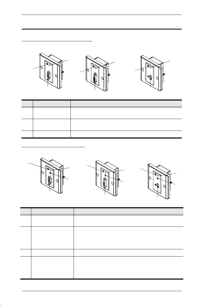
Front View (Transmitter)
VE157T
VE607T
VE807T
2
3
1
3
1
2
3
1
2
No. Component Description
1 Video IN Port The cable from your VGA / DVI / HDMI source device is
plugged in here.
2 Power LED The Power LED lights green to indicate that the unit is
receiving power.
3 Audio IN Port The cable from your audio source device is plugged in here.
Front View (Receiver)
VE157R VE807R
3
1
3
2
4
VE607R
1
3
2
4
1
2
4
No. Component Description
1 Video OUT Port The cable from your VGA / DVI / HDMI monitor plugs in
here.
2 Power/Link LED The Power LED lights green to indicate that the unit is
receiving power.
The Link LED lights orange to indicate that the connection
to the Transmitter unit has been established.
3 Audio OUT Port The cable from your speakers plugs in here.
4 Manual Gain Control
(VE157) /
EQ Switch (VE607 /
Use this knob to adjust the video quality by turning to the
right or left until you obtain the desired picture quality.
See Picture Adjustment, page 13 for more details.
VE807)
4
Introduction
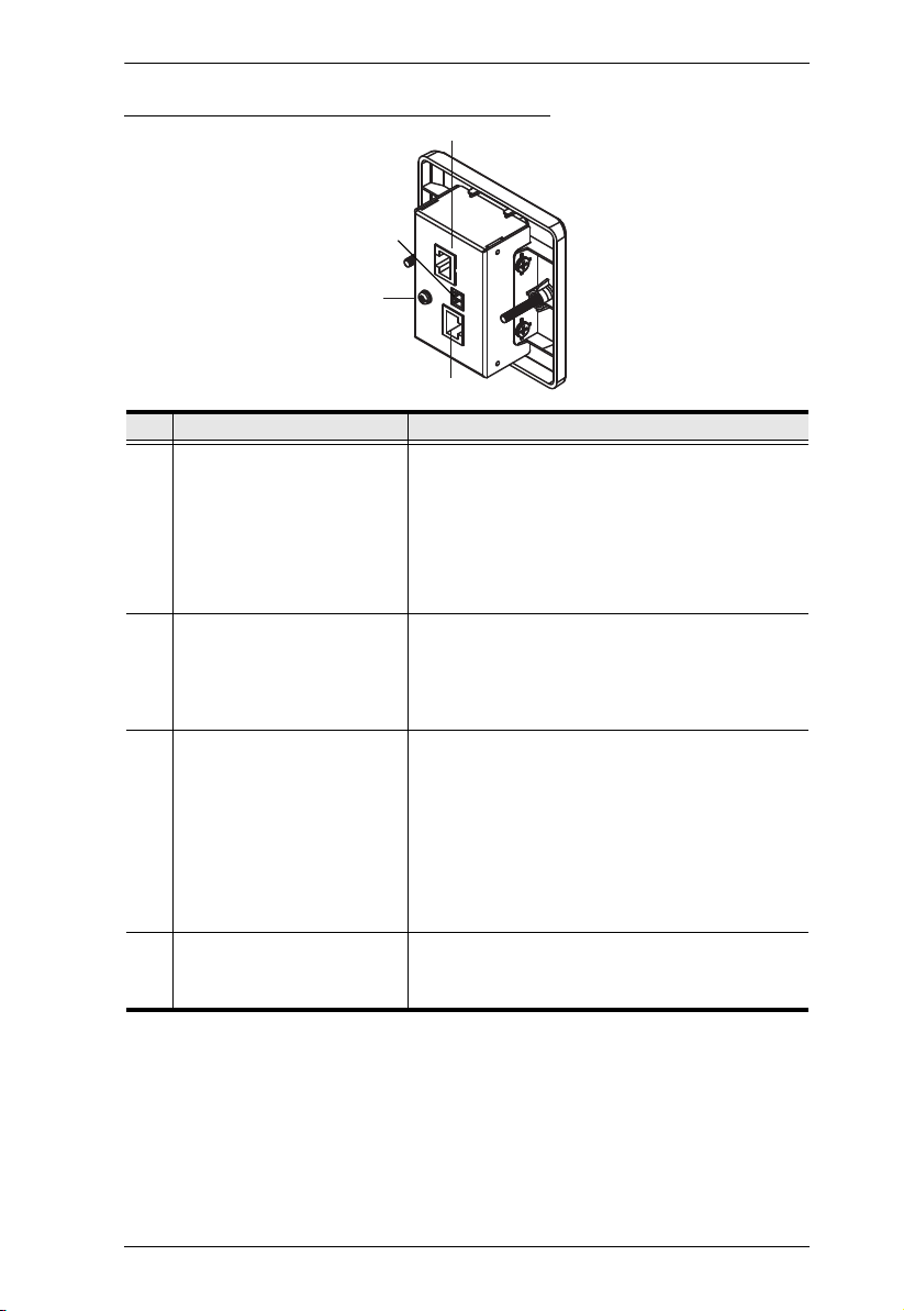
Rear View (Transmitter / Receiver)
3
2
4
1
No. Component Description
1 Line IN/OUT (VE157)
TMDS Port (VE607 / VE807)
2 Power (Terminal block) The power adapter wires (+9V and GND) plug in
3 Power Port (VE157)
DDC Port (VE607 / VE807)
4 Grounding Terminal The grounding wire is attached here.
The Cat 5e cable that connects the Transmitter
and Receiver units plugs in here. The Cat 5e
connection between these ports transmits video
and audio signals.
For VE157:
Transmitter (Line OUT)
Receiver (Line IN)
here.
See How to Supply Power, page 8 for the steps
on how to connect the terminal block to a power
source.
Use a Cat 5e cable to connect the Transmitter
and Receiver units through this port.
The second Cat 5e cable connection transmits the
power signal to either the Transmitter or Receiver
when only one of the units is supplied power via
the Terminal Block.
For VE607 / VE807, in addition to transmitting the
power signal, the second Cat 5e cable is used for
real EDID Bypass and HDCP key authentication.
Note: The grounding wire is not included in this
package.
5

VE157 / VE607 / VE807 User Manual
This Page Intentionally Left Blank
6

Chapter 2
1. Important safety information regarding the placement of this
device is provided on page 15. Please review it before
proceeding.
2. Make sure that the power to all devices connected to the
installation is turned off. You must unplug the power cords of
any computers that have the Keyboard Power On function.
Hardware Setup
Overview
For convenience and flexibility, the VE157 / VE607 / VE807 can be mounted
on the wall, ceiling, floor or any surface of your preference.
The dimensions of the VE157 / VE607 / VE807 are made to fit an area equal
to a standard wall plate.
For a neat finish, use the Wall Plate Covers that are included in the package
contents. For more information on the dimensions of the VE157 / VE607 /
VE807 fitted to a wall plate, see page 22.
Note: This chapter uses theVE807 panels for illustrating the installation steps.
Before Mounting
In order to mount the VE157 / VE607 / VE807, you first need to complete the
following instructions:
Prepare two installation sites (for the Transmitter and Receiver units) with the
proper dimensions (see image below) to accommodate the Wall Plate.
Make sure proper cabling (unit-to-unit via Cat 5e; unit-to-power) can be
supplied to both sites.
Wall Plate Dimensions
The installation site or wall plate should have a minimum depth measurement
of 4.5 cm (1.77 in.). For more information, see page 22.
7
 Loading...