

Page 1
User Manual
VE-120
Read this guide thoroughly and follow the installation and operation
procedures carefully in order to prevent any damage to the units and/or
any devices that connect to them.
This package contains:
M 1 VE-120L Video Extender (Local Unit)
M 1 VE-120R Video Extender (Remote Unit)
M 1 VGA Cable
M 2 Power Adapters
M 1 User Manual
If anything is damaged or missing, contact your dealer.
© Copyright 2008 ATEN
Manual Part No. PAPE - 1141-200
Printed in Taiwan 07/2008
®
International Co., Ltd.
Page 2
NOTE: This equipment has been tested and found to comply
with the limits for a Class B digital device pursuant to Subpart
J of Part 15 of FCC Rules. These limits are designed to provide
reasonable protection against harmful interference in a
residential installation. This equipment generates, uses and
can radiate radio frequency energy and, if not installed and
used in accordance with the instructions, may cause harmful
interference to radio communications. However, there is no
guarantee that interference will not occur in a particular
installation. If this equipment does cause harmful interference
to radio or television reception, which can be determined by
turning the equipment off and on, the user is encouraged to try
to correct the interference by one or more of the following
measures:
M Reorient or relocate the receiving antenna.
M Increase the separation between the equipment and
receiver.
M Connect the equipment into an outlet on a circuit different
from that which the receiver is connected.
M Consult the dealer or an experienced radio/television
technician for help.
Page 3

Overview
The VE-120 Video Extender System allows you to extend the
distance between the computer system unit and the display
monitor by up to 130 meters (430 feet). It accomplishes this by
means of a local transmitting unit (VE-120L), and remote
receiving unit (VE-120R), connected by Category 5 twisted pair
Ethernet cable.
The VE-120 Video Extender System is ideal for factory and
construction sites, or any installation where the display needs
to reside in a harsh setting, but you want the system equipment
kept in an environmentally friendly location.
The Extender System is also useful for control and security
purposes, where you can have the system unit in a secure area
at the same time that you put the display in an area that is
convenient for viewing.
Other useful applications for the Video Extender system include:
Financial: The remote display of stock market information.
Education: The remote display of lectures and lessons to
lecture halls and classrooms.
Business: The remote display of addresses to overf low
rooms; video conferencing; and demos.
- 1 -
Page 4

Features
Uses economical, reliable, Category 5 Ethernet cable to
M
connect the local and remote units
Easy installation - connecting cables is all it takes
M
High resolution video - up to 1024 x 768
M
Supports VGA, SVGA, and Multisync Monitors
M
Long distance transmission - up to 130m (430’)
M
System Requirements
A PC compatible computer with a VGA output port
M
A VGA, SVGA, or Multisync monitor
M
- 2 -
Page 5
Components
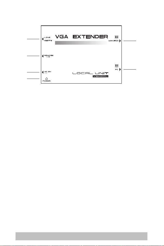
The Local Unit (VE-120L)
1
2
3
4
1. Range Sw itch
Slide the switch to the Long position if the Remote Unit is
located a long distance away; slide the switch to the Short
position if the Remote Unit is located a short distance away.
2. Remote I/O
The Category 5 twisted pair cable that connects to the
Remote Unit plugs in here.
3. AC 9V Power Jack
The AC 9V power adapter’s cable plugs in here.
4. Power LED
Lights to indicate that the unit is receiving power.
5. Monitor
The local monitor’s VGA cable plugs in here.
5
6
6. PC
The VGA cable (supplied with this package) that connects to
the computer’s VGA port plugs in here.
- 3 -
Page 6

The Remote Unit (VE-120R)
1
2
3
1. Remote I/O
The Category 5 twisted pair cable that connects to the
Remote Unit plugs in here.
2. AC 9V Power Jack
The AC 9V power adapter’s cable plugs in here.
3. Power LED
Lights to indicate that the unit is receiving power.
4. Monitor
The local monitor’s VGA cable plugs in here.
4
- 4 -
Page 7

Installation
1. Make sure that power to all the devices you will
be connecting up has been turned off. If your
computer has the Keyboard Power On function,
you must unplug its power cord.
2. To prevent damage to your installation, make sure
that all devices are properly grounded.
Setting up the Video Extender System is simply a matter of
plugging in the cables. Refer to the diagram below as you
perform the following installation procedures. The numbers in
the diagram correspond to the numbers of the steps:
1. Plug the male end of the VGA cable (supplied with this
package) into the computer’s video output port; plug the
female end of the cable into the Local Unit’s PC port.
2. Plug the local monitor’s VG A cable into the Local Unit ’s
Monitor port.
3. Plug one of the power adapt ers (supplied with this package)
into an AC source; plug the adapter’s power cable into the
Local Unit’s AC 9V Power Jack.
4. Slide the Local Unit’s Range Swit ch (see p. 3) to the Long
position if the Remote Unit location is a long distance away;
slide the switch to the Short position if the Remote Unit
location is a short distance away.
5. Plug either end of a Category 5 cable int o the Local Unit ’s
Remote I/O port; plug the other end of the Category 5 cable
into the Remote Unit’s I/O port.
1. Category 5 cable is not supplied with this package.
Note:
It requires a separate purchase. The cable can be
up to 130m long.
2. See the Cable Length table, p. 7, for typical
resolution/refresh rate/distance ratios.
- 5 -
Page 8

6. Plug the remote monit or’s VG A cable int o the Remot e Unit’s
Monitor port.
7. Plug the second power adapter (supplied wit h this package)
into an AC source; plug the adapter’s power cable into the
Remote Unit’s Power Jack.
8. Power On the computer and monit ors.
5
6
7
4
2
3
1
- 6 -
Page 9

Appendix
Cable Length Table
Resolution
640 x 480
800 x 600
1024 x 768
@ 60Hz @ 75Hz @ 85Hz
130 100
TP Pin Assignments
Pin Assignment
1
V OUT G
2
/V OUT G
3
V OUT B
4
V OUT R
5
/V OUT R
6
/V OUT B
7
GND
8
GND
Distance (meters)
100
100
- 7 -
Page 10

TP Wiring Diagram
PAIR 3
PAIR 2 PAIR 1
123456 78
W-O W-GO G W-Br BrBl W-Bl
JACK POSITIONS
PAIR 4
T568B
AT&T 258A
Troubleshooting
Symptom Action
No Video Make sure that all cables are securely plugged
into their sockets.
- 8 -
Page 11

Specifications
Function VE-120L VE-120R
Connectors Input 15 pin HDB male RJ-45 Socket
Output 15 pin HDB female
LEDs 1 Power
Video Resolution 640 x 480 @ 130m - 1024 x 768 @ 100m
Signal Type VGA, SVGA, Multisync
Cable
Type
RJ-45 Socket
Length
Power Consumption AC 9V 130mA (max) AC 9V 180mA (max)
Housing Metal
Weight .24Kg .22Kg
Dimensions (L x W x H) 11.9 x 8.6 x 5.8 cm
15 pin HDB female
Category 5 STP
130m (430’)
- 9 -
Page 12

Limited Warranty
IN NO EVENT SHALL THE DIRECT VENDOR’S LIABILITY
EXCEED THE PRICE PAID FOR THE PRODUCT FROM
DIRECT, INDIRECT, SPECIAL, INCIDENTAL, OR
CONSEQUENTIAL DAMAGES RESULTING FROM THE USE
OF THE PRODUCT, DISK, OR ITS DOCUMENTATION.
The direct vendor makes no warranty or representation,
expressed, implied, or statutory with respect to the contents or
use of this documentation, and especially disclaims its quality,
performance, merchantability, or fitness for any particular
purpose.
The direct vendor also reserves the right to revise or update the
device or documentation without obligation to notify any
individual or entity of such revisions, or update. For further
inquiries, please contact your direct vendor.
- 10 -
Page 13

Notes:
- 11 -
Page 14

Notes:
- 12 -
Page 15

Notes:
- 13 -
Page 16

Notes:
- 14 -
 Loading...