

8-Port Video Switch
Mini Cat 5 A/V Extender
VS881
VE022
User Guide
© Copyright 2011 ATEN® International Co., Ltd.
ATEN and the ATEN logo are trademarks of ATEN International Co., Ltd. All rights reserved. All other
trademarks are the property of their respective owners.
This product is RoHS compliant.
Part No. PAPE-1285-221G Printing Date: 03/2011
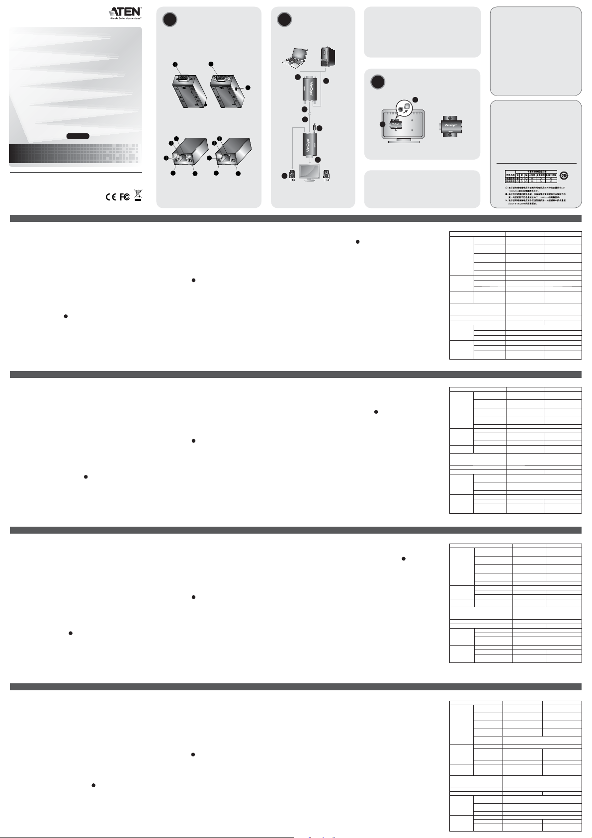
Hardware Review Installation
A
3
B. VE022R Front
View/Side View
1
D. VE022R Rear
View
5
4
1
2
2
3
A. VE022T
Front View
C. VE022T
Rear View
4
1
2
1
5
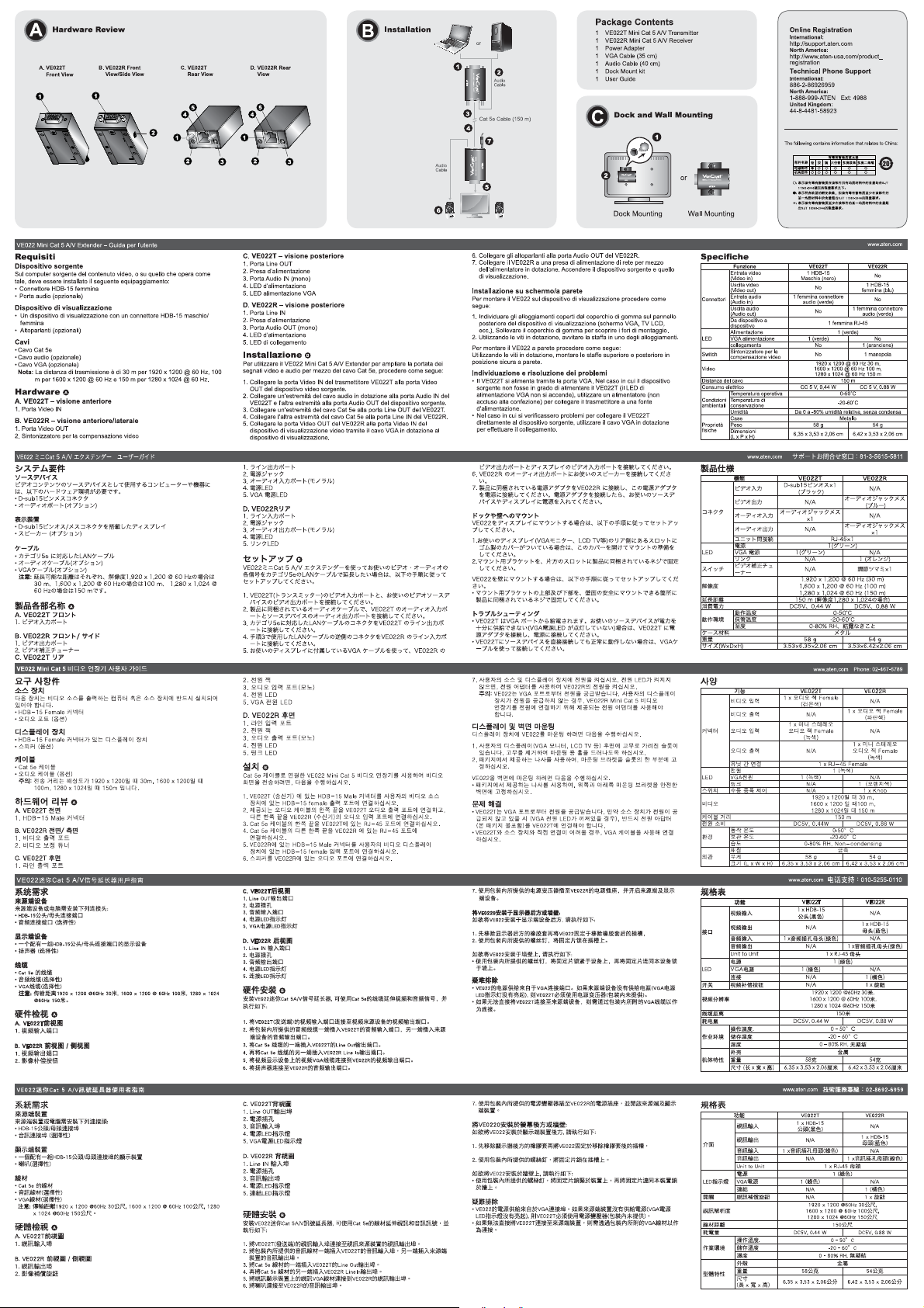
B
Package Contents
1 VE022T Mini Cat 5 A/V Transmitter
1 VE022R Mini Cat 5 A/V Receiver
1 Power Adapter
1 VGA Cable (35 cm)
1 Audio Cable (40 cm)
1 Dock Mount kit
1 User Guide
or
1
Mini Cat5 A/V Transmitter
2
Audio
Cable
<+:
VGA
POWER
POWER
3
Cat 5e Cable (150 m)
4
7
POWER
LINK
R
2
2
0
VE
r
ive
e
c
e
Audio
R
V
5 A/
t
Cable
Ca
i
n
i
M
Dock and Wall Mounting
C
1
2
Dock Mounting Wall Mounting
or
Mini Cat5 A/V Rece
VE022R
iver
5
6
All information, documentation, and specifications
contained in this media are subject to change without
prior notification by the manufacturer.
Please visit our website to find the most up to date
version.
FCC Information
This equipment has been tested and found to comply with
the limits for a Class B digital device, pursuant to Part 15
of the FCC Rules. These limits are designed to provide
reasonable protection against harmful interference in a
residential installation. This equipment generates, uses
and can radiate radio frequency energy, and if not installed
and used in accordance with the instruction manual, may
cause interference to radio communications. However,
there is no guarantee that interference will not occur in a
particular installation. If this equipment does cause harmful
interference to radio or television reception, which can be
determined by turning the equipment off and on, the user
is encouraged to try to correct the interference by one or
more of the following measures:
• Reorient or relocate the receiving antenna;
• Increase the separation between the equipment and
receiver;
• Connect the equipment into an outlet on a circuit different
from that which the receiver is connected;
• Consult the dealer/an experienced radio/television
technician for help.
Online Registration
International:
http://support.aten.com
North America:
http://www.aten-usa.com/product_
registration
Technical Phone Support
International:
886-2-86926959
North America:
1-888-999-ATEN Ext: 4988
United Kingdom:
44-8-4481-58923
The following contains information that relates to China:
VE022 Mini Cat 5 A/V Extender User Guide
Requirements
Source Device
The following equipment must be installed on the computer or source device
that acts at the source of video content:
• HDB-15 Male/Female connector
• Audio port (optional)
Display Device
• A display device with a HDB-15 Male/Female connector
• Speakers (optional)
Cables
• Cat 5e cable
• Audio cable (optional)
• VGA cable (optional)
Note: Transmission distance is 30 m for 1920 x 1200 @ 60 Hz, 100 m for
1600 x 1200 @ 60 Hz and 150 m for 1280 x 1024 @ 60 Hz.
Hardware Review A
A. VE022T Front View
1. Video IN Port
B. VE022R Front View / Side View
1. Video OUT Port
2. Video Compensation Tuner
C. VE022T Rear View
1. Line OUT Port
2. Power jack
Guide de l’utilisateur du mini-système d'extension A/V de catégorie 5 VE022
Configuration minimale
Périphérique source
L’équipement suivant doit être installé sur l’ordinateur ou le périphérique
utilisé comme source de contenu graphique :
• Connecteur femelle HDB-15
• Port audio (facultatif)
Périphérique d’affichage
• Un périphérique d’affichage doté d’un connecteur mâle/femelle HDB-15
• Des haut-parleurs (facultatifs)
Câbles
• Câble Ethernet de catégorie 5e
• Câble audio (facultatif)
• Câble VGA (facultatif)
Remarque: La distance de transmission est de 30 m pour une résolution
de 1920 x 1200 à 60 Hz, 100 m pour 1600 x 1200 à 60 Hz et
150 m pour 1280 x 1024 à 60 Hz.
Description de l’appareil A
A. VE022T – Vue avant
1. Port d’entrée vidéo
B. VE022R – Vue avant / vue latérale
1. Port de sortie vidéo
2. Réglage de la compensation vidéo
C. VE022T – Vue arrière
1. Port de sortie de ligne
VE022 Mini-Kat-5-A/V-Verlängerung Benutzerhandbuch
Voraussetzungen
Signalquelle
Auf den Signalquellen oder Computern, die das Grafiksignal senden, muss
mindestens Folgendes installiert sein:
• HDB-15-Buchse
• Audioport (optional)
Anzeigegerät
• Anzeigegerät mit HDB-15-Buchse (Männlein/Weiblein)
• Lautsprecher (optional)
Kabel
• Kat-5e-Kabel
• Audiokabel (optional)
• VGA-Kabel (optional)
Hinweis: Die maximale Übertragungslänge beträgt 30 m bei 1920 x 1200
und 60 Hz, 100 m bei 1600 x 1200 und 60 Hz und 150 m bei
1280 x 1024 und 60 Hz.
Hardwareübersicht A
A. Vorderseitige Ansicht des VE022T
1. Grafikeingang
B. Vorderseitige und seitliche Ansicht des VE022R
1. Grafikausgang
2. Bildsignalkompensationsregler
C. Rückseitige Ansicht des VE022T
1. Line-Out-Buchse
VE022 Alargador A/V Mini para cables de Cat. 5 Manual del usuario
Requisitos
Dispositivo fuente
En los dispositivos fuente de señal gráfica u ordenadores que se conectan
al equipo debe estar instalado lo siguiente:
• Conector HDB-15 hembra
• Puerto de audio (opcional)
Dispositivo de visualización
• Un dispositivo de visualización con conector HDB-15 macho/hembra
• Altavoces (opcional)
Cables
• Cable de Cat. 5e
• Cable de audio (opcional)
• Cable VGA (opcional)
Nota: La distancia de transmisión máxima es de 30 m para 1920 x 1200 a
60 Hz, 100 m para 1600 x 1200 a 60 Hz y 150 m para 1280 x 1024
a 60 Hz.
Presentación del hardware A
A. VE022T – Vista frontal
1. Puerto de entrada de señal gráfica
B. VE022R – Vista frontal/lateral
1. Salida de señal gráfica
2. Ajuste de compensación de señal gráfica
C. VE022T – Vista posterior
1. Salida de línea Line Out
3. Audio IN Port (mono)
4. Power LED
5. VGA Power LED
D. VE022R Rear View
1. Line IN Port
2. Power jack
3. Audio OUT Port (mono)
4. Power LED
5. Link LED
Installation B
To use the VE022 Mini Cat 5 A/V Extender to extend your video and audio
signals using Cat 5e cabling, do the following:
1. Connect the Video IN Port on VE022T (transmitter) to the Video OUT port
on your video source device.
2. Connect one end of the provided audio cable to the Audio IN port of the
VE022T and connect the other end to the audio OUT port of the source
device.
3. Connect one end of the Cat 5e cable to the Line OUT port on the VE022T.
4. Connect the other end of the Cat 5e cable to the Line IN port on the
VE022R .
5. Connect the Video OUT port on the VE022R to the Video IN port on your
video display device using the VGA cable that came with your display
device.
6. Connect your speakers to the audio OUT port on the VE022R.
2. Prise d’alimentation
3. Port d’entrée audio (mono)
4. Voyant d’alimentation
5. Voyant d'alimentation VGA
D. VE022R – Vue arrière
1. Port d’entrée de ligne
2. Prise d’alimentation
3. Port de sortie audio (mono)
4. Voyant d’alimentation
5. Voyant de liaison (Link)
Installation B
Pour utiliser le mini-système d’extension A/V de catégorie 5 VE022 pour
augmenter la distance de transmission de vos signaux vidéo et audio à l’aide
d’un câblage de catégorie 5e, procédez comme suit :
1. Connectez le port d’entrée vidéo du module VE022T (émetteur) au port
de sortie vidéo de votre périphérique vidéo source.
2. Connectez une extrémité du câble audio fourni au port d’entrée audio du
module VE022T et l’autre extrémité du câble au port de sortie audio du
périphérique source.
3. Connectez une extrémité du câble de catégorie 5e au port de sortie de
ligne du module VE022T.
4. Connectez l’autre extrémité du câble de catégorie 5e au port d’entrée de
ligne du module VE022R.
5. Connectez le port de sortie vidéo du module VE022R au port d’entrée
vidéo de votre périphérique d’affichage vidéo à l’aide du câble VGA livré
avec votre périphérique d’affichage.
2. Stromeingangsbuchse
3. Audio-Eingang (Mono)
4. LED-Betriebsanzeige
5. VGA-Betriebsanzeige
D. Rückseitige Ansicht des VE022R
1. Line-In-Buchse
2. Stromeingangsbuchse
3. Audio-Ausgang (Mono)
4. LED-Betriebsanzeige
5. Verbindungsanzeige
Installation B
Um den Kabelweg zu Ihrem Bildschirm und zu Ihren Lautsprechern mit der
VE022 Mini-Kat 5-A/V-Verlängerung über ein Kat. 5e-Kabel zu erweitern,
gehen Sie folgendermaßen vor:
1. Verbinden Sie den Grafikeingang am VE022T (Sender) mit dem
Grafikausgang Ihrer Grafiksignalquelle.
2. Verbinden Sie das eine Ende des mitgelieferten Audiokabels mit dem
Audioeingang am VE022T. Verbinden Sie das andere Ende mit dem
Audioausgang der Signalquelle.
3. Verbinden Sie das eine Ende eines Kat. 5e-Kabels mit der Line-OutBuchse am VE022T.
4. Verbinden Sie das andere Ende eines Kat. 5e-Kabels mit der Line-InBuchse am VE022R.
5. Verbinden Sie den Grafikausgang des VE022R mit dem Grafikeingang
des Anzeigegerätes. Verwenden Sie dazu das zum Anzeigegerät
gehörige VGA-Kabel.
2. Entrada de alimentación
3. Entrada de audio (monoaural)
4. Indicador LED de alimentación
5. Indicador LED de alimentación vía VGA
D. VE022R – Vista posterior
1. Entrada de línea Line-In
2. Entrada de alimentación
3. Salida de audio (monoaural)
4. Indicador LED de alimentación
5. Indicador de enlace (Link)
Instalación B
Para emplear el alargador Mini de señales A/V para cables de Cat. 5 VE022
y así ampliar la distancia hasta su pantalla con cable de Cat. 5e, proceda
como se indica a continuación:
1. Conecte la entrada de señal gráfica del VE022T (transmisor) a la salida
de señal gráfica de su dispositivo fuente de señal gráfica.
2. Conecte un extremo del cable de audio incluido a la entrada de audio del
VE022T y el otro extremo a la salida de audio del dispositivo fuente de
señal gráfica.
3. Conecte un extremo del cable de Cat. 5e al puerto de salida de línea Line
Out del VE022T.
4. Conecte el otro extremo del cable de Cat. 5e al puerto de entrada de
línea Line In del VE022R.
5. Conecte el puerto de salida de señal gráfica del VE022R a la entrada
de señal gráfica de su dispositivo de visualización. Para ello, emplee el
cable VGA incluido con el dispositivo de visualización.
7. Connect the VE022R to a power outlet using the provided power adapter.
Power on your source and display devices.
Dock and Wall Mounting
To mount the VE022 on the display device do the following:
1. At the rear panel your display (VGA monitor, LCD TV, etc.) locate the
rubber-covered slots. Lift off the rubber to expose the holes for mounting.
2. Using the screws provided with this package, screw the mounting bracket
into one of the slots.
To mount the VE022 on a wall do the following:
• Using the screws provided with this package, screw top and bottom
mounting brackets into a secure position on the wall.
Troubleshooting
• The VE022T gets its power supply from the VGA port. If your source
device is not capable of supplying power (VGA power LED does not
light up), you must use a power adapter (not included in the package) to
connect the VE022T to a power source.
• If the VE022T has trouble connecting directly to the source device, kindly
use the VGA cable provided to make the connection.
6. Branchez vos haut-parleurs sur le port de sortie audio du module
VE022R.
7. Branchez le module VE022R sur une prise de courant à l’aide de
l’adaptateur secteur fourni. Allumez les périphériques d'affichage et
source.
Installation sur l’écran ou au mur
Pour installer le VE022 sur le périphérique d’affichage, procédez comme
suit :
1. Localisez les orifices protégés par des bouchons en caoutchouc à l’arrière
de votre périphérique d’affichage (moniteur VGA, téléviseur LCD, etc.).
Retirez les bouchons pour découvrir les orifices que vous utiliserez pour
l’installation.
2. À l’aide des vis fournies dans cet emballage, vissez le support de
montage dans les orifices.
Pour monter le VE022 au mur, procédez comme suit :
• À l’aide des vis fournies dans cet emballage, vissez les supports de
montage supérieur et inférieur dans le mur dans une position sûre.
Résolution des problèmes
• Le module VE022T est alimenté en électricité par le port VGA. Si votre
périphérique n’est pas en mesure de l’alimenter en électricité (dans ce
cas le voyant d’alimentation VGA reste éteint), vous devez utiliser un
adaptateur secteur (non fourni) pour brancher le module VE022T à une
prise de courant.
• Si le module VE022T ne peut pas être connecté directement au
périphérique source, veuillez utiliser le câble VGA fourni pour réaliser le
raccordement.
6. Verbinden Sie die Lautsprecher mit dem Audioausgang des VE022R.
7. Verbinden Sie den VE022R über das mitgelieferte Netzteil mit dem
Stromnetz. Schalten Sie die Signalquelle und die Anzeigegeräte ein.
Auf Anzeigegerät bzw. an der Wand montieren
Um den VE022 auf dem Anzeigegerät zu montieren, gehen Sie
folgendermaßen vor:
1. Machen Sie die Schraubgewinde für die Wandmontage auf der Rückseite
Ihres Anzeigegerätes (VGA-Monitor, LCD-TV usw.) ausfindig. Entfernen
Sie ggf. die darüber vorhandenen Schutzkappen.
2. Schrauben Sie mit den mitgelieferten Schrauben den Montagerahmen an
einer der Aussparungen fest.
Um den VE022 an der Wand zu montieren, gehen Sie folgendermaßen vor:
• Schrauben Sie mit den mitgelieferten Schrauben den oberen und den
unteren Montagerahmen an der Wand fest.
Problemlösung
• Normalerweise wird der VE022T über den VGA-Anschluss mit Strom
versorgt. Falls die Signalquelle nicht ausreichend Strom liefern kann (die
VGA-Betriebsanzeige leuchtet nicht), müssen Sie ein Netzteil (nicht im
Lieferumfang enthalten) anschließen, um den VE022T mit dem Stromnetz
zu verbinden.
• Falls Sie Schwierigkeiten beim Verbinden des VE022T mit der Signalquelle
haben, stellen Sie die Verbindung über das mitgelieferte VGA-Kabel her.
6. Conecte los altavoces al puerto de salida de audio del VE022R.
7. Enchufe el VE022R a la red eléctrica. Para ello, emplee el adaptador de
alimentación incluido. Encienda los dispositivos de visualización y fuente.
Montaje sobre dispositivo de visualización y en pared
Para montar el VE022 sobre el dispositivo de visualización, proceda como
se indica a continuación:
1. Busque los orificios para el montaje en pared en la parte posterior de su
pantalla (monitor VGA, televisor LCD etc.). En caso de que estuvieran
tapados con tapas protectoras, retírelas.
2. Fije el marco de montaje incluido en una de las ranuras para montaje en
pared. Para ello, emplee los tornillos incluidos.
Para montar el VE022 en la pared, proceda como se indica a continuación:
• Instale los marcos de montaje superior e inferior firmemente en la pared.
Para ello, emplee los tornillos incluidos.
Resolución de problemas
• El VE022T recibe la alimentación del puerto VGA. Si su dispositivo fuente
de señal no suministrara suficiente potencia en el puerto VGA (el indicador
de alimentación vía VGA no se enciende), deberá conectar un adaptador
de alimentación (no incluido) para conectar el VE022T a una fuente de
alimentación eléctrica.
• Si el VE022T no pudiera establecer la conexión con el dispositivo fuente
de señal gráfica, emplee el cable VGA incluido para interconectar los
dispositivos.
C
C
C
Specifications
Function VE022T VE022R
Video In
Video Out N/A
Connectors
Audio In
Audio Out N/A
Unit to Unit 1 x RJ-45 Female
Power 1 (Green)
LEDs
VGA Power 1 (Green) N/A
Link N/A 1 (Orange)
Video
Switch
Compensation
Tuner
Video
Cable Distance 150 m
Power Consumption DC5V, 0.44 W DC5V, 0.88 W
Operating Temp. 0-50°C
Environment
Storage Temp. -20-60°C
Humidity 0-80% RH, Non-condensing
Housing Metal
Physical
Weight 58 g 54 g
Properties
Dimensions
(L x W x H)
Caractéristiques techniques
Fonction VE022T VE022R
Entrée vidéo
Sortie vidéo N/D
Connecteurs
Entrée audio
Sortie audio N/D
Port d'unité à unité 1 connecteur RJ-45 femelle
Alimenta tion 1 (vert)
Voyant d'alimen tation
Voyants
VGA
de liaison N/D 1 (orange)
Réglage de la
Commutateur
compensa tion vidéo
Vidéo
Longueur de câble 150 m
Consommation électrique 5 Vcc, 0,44 W 5 Vcc, 0,88 W
Température de
fonctionne ment
Environne ment
Température de
stockage
Humidité Humidité relative de 0 à 80 %, sans condensation
Boîtier Métallique
Poids 58 g 54 g
Propriétés
physiques
Dimensions
(Long x Larg x Haut)
Technische Daten
Funktion VE022T VE022R
Grafikein gänge
Grafikaus gänge --
Anschlüsse
Audio-Eingänge
Audio-Ausgang -Gerät an Gerät 1 x RJ-45 Weiblein
Stromver sorgung 1 (grün)
LED-Anzeigen
VGA-Betriebs anzeige 1 (grün) -Ver bindung -- 1 (orange)
Bildsignal kompensa-
Schalter
tionsregler
Grafik
Kabellänge 150 m
Stromverbrauch 5 V=, 0,44 W 5 V=, 0,88 W
Betriebs temperatur 0-50°C
Lagertem peratur -20-60°C
Umgebung
Feuchtigkeit
Gehäuse Metall
Physische
Gewicht 58 g 54 g
Eigenschaften
Abmessun gen
(L x B x H)
Especificaciones
Función VE022T VE022R
Entrada de señal
gráfica
Salida de señal
gráfica
Entra da de audio
Conectores
Salida de audio -Puerto de unidad a
unidad
Alimentación 1 (verde)
Indicador LED de
Indicadores
alimenta ción vía
LED
VGA
Enlace -- 1 (naranja)
Ajuste de
Conmutador
compensa ción de
señal gráfica
Señal gráfica
Longitud de cable 150 m
Consumo 5 V de c.c., 0,44 W 5 V de c.c., 0,88 W
Temperatura de
funciona miento
Temperatura de
Entorno
almacena miento
Humedad 0 a 80% de HR, sin condensar
Carcasa Metálica
Peso 58 g 54 g
Propiedades
físicas
Dimensiones
(L x An x Al)
1 x HDB-15
Male (Black)
1 x Audio Jack
Female (Green)
N/A 1 x Knob
1920 x 1200 @ 60 Hz at 30 m
1600 x 1200 @ 60 Hz at 100 m
1280 x 1024 @ 60 Hz at 150 m
6.35 x 3.53 x 2.06 cm 6.42 x 3.53 x 2.06 cm
1 x HDB-15
Mâle (Noir)
1 Prise audio femelle
(vert)
1 (vert) N/D
N/D 1 bouton
une résolution de 1920 x 1200 à 60 Hz 30 m,
1600 x 1200 à 60 Hz 100 m,
1280 x 1024 à 60 Hz 150 m
6,35 x 3,53 x 2,06 cm 6,42 x 3,53 x 2,06 cm
1 x HDB-15
Männlein (schwarz)
1 x Audio-Buchse
Weiblein (grün)
1920 x 1200 und 60 Hz 30 m,
1600 x 1200 und 60 Hz 100 m,
1280 x 1024 und 60 Hz 150 m
0-80% rel. Luftfeuchte, nicht
6,35 x 3,53 x 2,06 cm6,42 x 3,53 x 2,06
1 x HDB-15
Macho (Negro)
--
1 Conector de audio
hembra (verde)
1 conector RJ-45 hembra
1 (verde) --
-- 1 botón
1920 x 1200 a 60 Hz 30 m,
1600 x 1200 a 60 Hz 100 m,
1280 x 1024 a 60 Hz 150 m
6,35 x 3,53 x 2,06 cm 6,42 x 3,53 x 2,06 cm
www.aten.com
N/A
1 x HDB-15
Female (Blue)
N/A
1 x Audio Jack
Female (Green)
www.aten.com
N/D
1 x HDB-15
femelle (bleu)
N/D
1 Prise audio femelle
(vert)
0 à 50 °C
-20 à 60 °C
www.aten.com
--
1 x HDB-15
Weiblein (blau)
--
1 x Audio-Buchse
Weiblein (grün)
-- 1 x Drehregler
kondensierend
cm
www.aten.com
--
1 x HDB-15
hembra (azul)
--
1 Conector de audio
hembra (verde)
0 a 50 °C
-20 a 60 °C
 Loading...