

Page 1

USB 2.0 P e ripher al Switc h
US ER MANUAL
US221A / US421A
Page 2

FCC Information
FEDERAL COMMUNICATIONS COMMISSION INTERFERENCE
STATEMENT: This equipment has been tested and found to comply
with the limits for a Class B digital service, pursuant to Part 15 of the
FCC rules. These limits are designed to provide reasonable
protection against harmful interference in a residential installation.
Any changes or modifications made to this equipment may void the
user’s authority to operate this equipment. This equipment generates,
uses, and can radiate radio frequency energy. If not installed and
used in accordance with the instructions, may cause harmful
interference to radio communications. However, there is no
guarantee that interference will not occur in a particular installation.
If this equipment does cause harmful interference to radio or
television reception, which can be determined by turning the
equipment off and on, the user is encouraged to try to correct the
interference by one or more of the following measures:
Reorient or relocate the receiving antenna.
Increase the separation between the equipment and receiver.
Connect the equipment into an outlet on a circuit different from
that to which the receiver is connected.
Consult the dealer or an experienced radio/TV technician for help.
FCC Caution: Any changes or modifications not expressly approved
by the party responsible for compliance could void the user's authority
to operate this equipment.
This device complies with Part 15 of the FCC Rules. Operation is
subject to the following two conditions:
(1) this device may not cause harmful interference, and
(2) this device must accept any interference received, including
interference that may cause undesired operation.
KCC Statement
RoHS
This product is RoHS compliant.
Page 3
US221A / US421A User Manual
Online Registration
You can register your product at our online support center:
International http://support.aten.com
Online Support
International
Email Support support@aten.com
Online
Support
Telephone Support
For telephone support, call this number:
International 886-2-8692-6959
China 86-400-810-0-810
Japan 81-3-5615-5811
Korea 82-2-467-6789
North America 1-888-999-ATEN ext 4988
Technical Support http://support.aten.com
Troubleshooting
Documentation
Software Updates
1-9 49 -428 -1111
http://www.aten.com
- 3 -
Page 4

North America
Email Support support@aten-usa.com
Online
Technical
Support
Telephone Support 1-888-999-ATEN ext 4988
Troubleshooting
Documentation
Software
Updates
http://www.aten-usa.com/support
1-949-428-1111
- 4 -
Page 5

Package Contents
Copyright © 2020 ATEN® International Co., Ltd.
Manual Part No. PAPE-1245-110G
Manual Date: 2020-06-18
ATEN and the ATEN logo are trademarks of ATEN International Co., Ltd. All rights
reserved. All other trademarks are the property of their respective owners.
The US221A / US421A USB 2.0 Peripheral Switch package
contains the following items:
1 2-port (US221A) or 4-port (US421A) USB 2.0 Peripheral
Switch
1 1.8 m USB Type A to USB Type B Cable
1 User Instructions*
Check to make sure that all the components are present and that
nothing got damaged in shipping. If you encounter a problem,
contact your dealer.
Read this manual thoroughly and follow the installation and
operation procedures carefully to prevent any damage to the unit,
and/or any of the devices connected to it.
* Features may have been added to the US221A / US421A since
this manual was printed. Please visit our website to download
the most up-to-date version of the manual.
- 5 -
Page 6

Overview
The US221A / US421A is a 2/4-port USB 2.0 Peripheral Switch
that allows up to 2/4 computers to share the use of a single USB
peripheral device (such as a printer, scanner, mass storage drive,
etc.*) on a one-at-a-time basis.
The peripheral focus can be given to a computer manually by
using pushbuttons on the switch or by using the software-based
configuration utility. In addition, the US221A / US421A has a new
Auto Switch function that stores commands sent to the USB
peripheral device to be processed on a first-come, first-served
basis, meaning that a print server is not required.
Compatible with both Windows and Mac, and with multifunction
printer support, the US221A / US421A is the ideal way to share
the latest USB 2.0 peripherals in a multimedia SOHO
environment.
Note: The US221A / US421A does not support a USB hub
peripheral device.
- 6 -
Page 7

Features
Enables two (US221A) or four (US421A) computers to share
a single USB peripheral device
Simple port selection via pushbuttons or easy-to-use
configuration utility
Auto Switch function – no need for a separate print server
USB 2.0 compliant
Supports transfer rates up to 480 Mbps
Multiplatform support – Windows and Mac
LED indicators display port focus
Overcurrent protection
Bus-powered
Hot pluggable
Buzzer indicates switching between computers
Supports multifunction printers
- 7 -
Page 8
System Requirements
Computers
The following equipment must be installed on each computer that
is to be connected to the system:
USB host controller
Cables
USB to USB cables to connect the computers to the
peripheral device.
Note: Only one USB Type A to USB Type B cable is provided
in the US221A / US421A package. You will need to
purchase an additional USB Type A to USB Type B
cables for each computer you wish to connect to the
US221A / US421A.
Operating Systems
Supported operating systems are shown in the table, below:
OS Version
Windows 2000, XP, 2003, 2008, Vista
Mac OS X 10.4.5, 10.5
- 8 -
Page 9
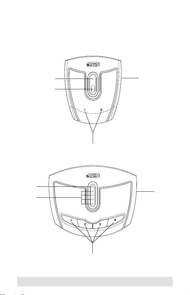
Components
Top View
1
2
3
1
3
4
4
2
- 9 -
Page 10

Rear View
5
6
5
6
No. Component Description
1 Lock LED Lights orange to show that the US221A /
2 Port Selection
Pushbutton(s)
3 Port Selected
LEDs
4 Beeper On/Off
Switch (on side)
5 USB Type B
Computer Port
6 USB Type A
Peripheral Port
US421A is locked.
Pressing a Port Selection Pushbutton brings
control to the computer attached to its
corresponding port. See Manual Operation –
Pushbutton, page 13 for further details.
Lights green to show that the computer
attached to its corresponding port has control.
Use this recessed switch to turn the US221A /
US421A’s beeper on or off.
Your computers plug into these ports. See
Installation, page 11 for further details.
Your USB 2.0 peripheral device plugs into this
port.
- 10 -
Page 11

Installation
1. Make sure that the power to any device that you
connect to the installation has been turned off and
that all devices are properly grounded.
The US221A / US421A USB 2.0 Peripheral Switch provides 2/4
USB Type B ports for computers to connect to, and one USB
Type A port for the peripheral device (multifunction printer,
scanner, mass storage device, etc.) that the computers will
share.
To install the US221A / US421A, do the following:
1. Use your USB device's USB cable to connect it to the
US221A / US421A's USB Type A port.
2. Plug the USB Type B connector of the USB Type A to USB
Type B cable provided with the US221A / US421A package
into any available port on the US221A / US421A.
3. Plug the Type A connector into the computer’s USB host port.
Repeat steps 2 and 3 for any other computers you are installing.
Note: Only one USB Type A to USB Type B cable is provided in
the US221A / US421A package. You will need to
purchase an additional USB Type A to USB Type B cables
for each computer you wish to connect to the US221A /
US421A.
- 11 -
Page 12

1
2
3
- 12 -
Page 13

Manual Operation – Pushbutton
Note: Manual operation and the software-based configuration
utility operate independently; commands from one will not
override the other.
US221A
To toggle the USB peripheral focus between the two computers,
press the port selection pushbutton (located on the top of the
unit). The selected port LED flashes and the unit beeps. When
the flashing stops and the LED becomes steady (in about four
seconds), that port has the peripheral focus.
US421A
To switch the peripheral focus to another port, press the
pushbutton that corresponds to that port. The selected port LED
flashes and the unit beeps. When the flashing stops and the LED
becomes steady (in about four seconds), that port has the
peripheral focus.
Lock/Unlock Peripheral Focus
To lock the peripheral focus on a certain computer, press and
hold the pushbutton that corresponds to that port for two
seconds, or until the orange LED lights up.
To unlock the peripheral focus, press and hold the pushbutton
that corresponds to that port for one second, or until the orange
LED turns off.
- 13 -
Page 14

Software Operation
Installing the Configuration Utility
The US221A / US421A has a software-based configuration utility
that can be used to configure the US221A / US421A's settings,
such as the Auto Switch function, Manual Switch and Release
reminder, and sound effects. The utility can also be used to lock
and unlock control of the US221A / US421A.
Note: Microsoft Windows users should login as an administrator
to install and launch the US221A / US421A software.
To install the configuration utility, do the following:
Note: 1. Below examples are based on a Windows 10 operating
1. From a computer that is connected to the US221A / US421A
2. Choose the Software Installation Package you want to install
system.
2. The screens shown in this section are for reference
only. The wording and layout of the actual screens put
up by the Software Installation Utility may vary slightly
from these examples.
using USB Type A to USB Type B cable, go to our Aten
Support & Download → Downloads site and choose the
model name that relates to your device (US221A / US421A)
to get a list of available Software Installation Packages.
(usually the most recent), and download it to your computer.
- 14 -
Page 15

3. Extract and open the downloaded software installation
package file, right click on the Setup icon, and select Run as
administrator as shown in the picture below.
4. The Software Installation Utility welcome screen appears, and
select Next.
- 15 -
Page 16

5. To choose a destination location, click Change, or click Next to
continue.
6. A confirmation screen appears, click Next to begin the
upgrade.
- 16 -
Page 17

7. After the upgrade has completed, you will be asked to restart
the PC. Click Yes to restart the PC now, or click No to restart
the PC later, then click Finish to exit the Software Installation
Utility.
8. When the installation completes, an icon labeled USB 2.0
Peripheral Switch Utility appears on your desktop and
another icon appears in your system tray.
The icon on your system tray displays in four colors to indicate
the US221A / US421A’s status, as shown in the following table:
Color Status
Green Locked on local computer
Yellow Connected to local computer
Red Peripheral device not connected
Grey Disconnected or busy
- 17 -
Page 18

Basic Operation
When you click on the icon in your system tray, a menu bar of
shortcuts appears. The first item at the top of the menu is one of
four shortcuts, depending on the current status of the US221A /
US421A. Shortcut options are Lock Connection, Unlock
Connection, Switch to Local Computer, and Cancel Switch
Request.
Lock / Unlock Connection
To lock the connection from your computer to the USB peripheral,
click on the icon in the system tray and select Lock Connection.
This method is a toggle between Lock and Unlock, so to unlock
the connection, do the same but click Unlock Connection.
Switch to Local Computer
To bring the control of the USB peripheral device to your
computer, click on the icon in the system tray and select Switch
to Local Computer.
Cancel Switch Request
If you have sent a request to the USB peripheral device and the
USB peripheral device is busy, your request is queued. To cancel
a sent request, click on the icon in the system tray and select
Cancel Switch Request.
- 18 -
Page 19

Advanced Operation and Settings
To use the Configuration Utility to view and change the US221A
/ US421A’s settings, click on the icon in your system tray and
select Settings. The following dialog box appears:
Auto Switch and Release
Enable these buttons to activate the US221A / US421A’s Auto
Switch function for a printer or other devices.
When Auto Switch and Release is enabled, commands sent to
the USB peripheral device are stored to be processed on a firstcome, first-served basis. Control of the US221A / US421A and
the USB peripheral device is locked on the computer currently
performing the action and then automatically released after the
action is completed.
- 19 -
Page 20

Printers
If your USB device is a printer or MFP (multifunction printer) and
you wish to use its print function, enable the Print Function Only
button and select the printer from the drop-down menu.
Note: 1. If the USB peripheral device is a printer, you do not
need a separate print server.
2. If you cannot find your printer in the drop-down menu,
the printer may need to be reinstalled. See
Troubleshooting, page 23 for further details.
3. If your printer is a multifunction printer and you want to
use its scan function, you must also enable the Other
Devices/Applications button if these functions have
dedicated applications. See Multifunction Printers,
page 21 for further details.
Other Devices
To add another device (such as a scanner) and associate its
application with the Auto Switch function, enable the Other
Devices/Applications button and click Add. In the dialog box that
appears, click Browse to search for the application program.* (In
Microsoft Windows only, you can also key in the device name for
easy reference).
Note: Be sure to search for the full application path. A desktop
shortcut, for example, does not work.
Once a device and application has been associated with the Auto
Switch function, the US221A / US421A automatically takes
control of the attached USB 2.0 peripheral when the application
is opened. Control is released when the application is closed.
- 20 -
Page 21

Multifunction Printers
If your printer is a multifunction printer and you want to
use its print and scan functions, you must enable both
the Print Function Only and the Other Devices/
Applications buttons, if these functions have dedicated
applications.
If your USB 2.0 peripheral device is a multifunction printer and
you wish to use its scan function, there are three ways to do this:
If the multifunction printer’s scan function have dedicated
applications, enable both the Print Function Only and the
Other Devices/Applications buttons and click Add. In the
dialog box that appears, click Browse to search for the
application program. (In Microsoft Windows only, you can
also key in the device name for easy reference).
Simply operate the US221A / US421A manually. See Manual
Operation – Pushbutton, page 13.
Use the shortcut in the system tray. See Basic Operation,
page 18.
To use the fax function of a multifunction printer, operate the
US221A / US421A manually. See Manual Operation –
Pushbutton, page 13.
- 21 -
Page 22

Manual Switch and Release
If the US221A / US421A is operating under manual control (with
a USB 2.0 peripheral such as a storage device, for example),
enable this button to set the time for a reminder to release control
of the US221A / US421A. The reminder will appear as a dialog
box on screen of the PC currently in control of the US221A /
US421A.
General
Enable this button to turn the US221A / US421A’s configuration
utility beeper on.
Note: 1. This enables the software beeper. To enable/disable
the hardware beeper, use the On/Off switch located on
the side of the US221A / US421A unit.
2. Default settings are Enabled.
- 22 -
Page 23

Troubleshooting
First, make sure that all cables are securely attached and seated
completely in their sockets.
Problem Possible Cause Action
Unit operates
erratically
Printer does not
appear in
configuration
utility.
Monitor program
of a printer does
not respond / Print
error messages
are generated
The Lock / Unlock
function does not
respond
Auto Switch print
function does not
respond.
Auto Switch
function for other
devices does not
release control
after application
closes.
Static electricity may
cause the unit to
operate erratically.
Printer was not
installed correctly.
The printer’s USB port
is configured for a PC;
the US221A / US421A
is in Auto Switch
mode.
The too rapid or
continuous
connecting /
disconnecting of a
USB connector from a
locked port can cause
the status of the lock
to be misread.
OS printer settings not
sent / not set correctly.
OS failed to close the
application.
Disconnect the
appropriate USB cable
from the US221A /
US421A port, then
reconnect it.
Re-install the printer; the
configuration utility will
now find the printer.
Disable the Auto Switch
function and operate the
US221A / US421A
manually.
Disconnect all USB cables
from the US221A /
US421A, then reconnect
them.
Reboot your PC to reestablish settings, or reinstall the Configuration
Utility. See Software
Operation, page 14.
Manual close the
application in your OS.
- 23 -
Page 24

Specifications
Function US221A US421A
Computer Connections 2 4
Computer Selection Pushbuttons, Software, Auto Switch
Connectors Computer 2 x USB Type B 4 x USB Type B
Device 1 x USB Type A
LEDs Device 1 (Orange)
Selected 2 (Green) 4 (Green)
Switches 2 x Pushbutton 4 x Pushbutton
Power Supply USB Bus Powered
Power Consumption DC5V, 2.5W
Environment Humidity 0–80% RH, Non-condensing
Storage Temp. -20–60ºC
Operating Temp. 5–40ºC
Physical
Properties
Housing Plastic
Weight 54 g 97 g
Dimensions
(L x W x H)
7.20 x 6.60 x 2.50 cm 10.20 x 7.60 x 2.30
cm
- 24 -
Page 25

Limited Warranty
ATEN warrants its hardware in the country of purchase against
flaws in materials and workmanship for a Warranty Period of two
[2] years (warranty period may vary in certain regions/countries)
commencing on the date of original purchase. This warranty
period includes the LCD panel of ATEN LCD KVM switches.
Select products are warranted for an additional year (see A+
Warranty for further details). Cables and accessories are not
covered by the Standard Warranty.
What is covered by the Limited Hardware Warranty
ATEN will provide a repair service, without charge, during the
Warranty Period. If a product is detective, ATEN will, at its
discretion, have the option to (1) repair said product with new or
repaired components, or (2) replace the entire product with an
identical product or with a similar product which fulfills the same
function as the defective product. Replaced products assume the
warranty of the original product for the remaining period or a
period of 90 days, whichever is longer. When the products or
components are replaced, the replacing articles shall become
customer property and the replaced articles shall become the
property of ATEN.
To learn more about our warranty policies, please visit our
website:
http://www.aten.com/global/en/legal/policies/warranty-policy
- 25 -
Page 26

MEMO
- 26 -
Page 27

MEMO
- 27 -
Page 28

MEMO
- 28 -
 Loading...