


Professional Online UPS
OL1000HV / OL1000SHV / OL1500HV / OL2000HV /
OL2000SHV / OL3000HV / OL1000LV / OL1000SLV /
OL1500LV / OL2000LV / OL2000SLV / OL3000LV
User Manual
www.aten.com

UPS User Manual
EMC Information
FEDERAL COMMUNICATIONS COMMISSION INTERFERENCE
STATEMENT: This equipment has been tested and found to comply
with t he l i mit s fo r a C l a ss A dig i tal devi ce, p urs u ant t o P a rt 15 of the FCC
Rules. These limits are designed to provide reasonable protection
against harmful interference when the equipment is operated in a
commercial environment. This equipment generates, uses, and can
radiate radio frequency energy and, if not installed and used in
accordance with the instruction manual, may cause harmful
interference to radio communications. Operation of this equipment in a
residential area is likely to cause harmful interference in which case the
user will be required to correct the interference at his own expense.
FCC Caution: Any changes or modifications not expressly approved by
the party responsible for compliance could void the user's authority to
operate this equipment.
Warning: Operation of this equipment in a residential environment
could cause radio interference.
Warning: For currents lower than 16A, this is a category C2 UPS
product. In a residential environment, this product may cause radio
interference, in which case the user may be required to take additional
measures.
Warning: For currents greater than 16A, this is a product for
commercial and industrial application in the second environment
installation restrictions or additional measures may be needed to
prevent disturbances.
This device complies with Part 15 of the FCC Rules. Operation is
subject to the following two conditions:
(1) this device may not cause harmful interference, and
(2) this device must accept any interference received, including
interference that may cause undesired operation.
ii

UPS User Manual
KCC Statement
이 기기는 업무용(A 급 ) 전자파적합기기로서 판매자 또는 사용자는 이
점을 주의하시기 바라며 , 가정외의 지역에
서 사용하는 것을 목적으로
합니다 .
RoHS
This product is RoHS compliant.
iii

UPS User Manual
User Information
Online Registration
Be sure to register your product at our online support center:
International http://eservice.aten.com
Telephone Support
For telephone support, call this number:
International 886-2-8692-6959
China 86-400-810-0-810
Japan 81-3-5615-5811
Korea 82-2-467-6789
North America 1-888-999-ATEN ext 4988
1-949-428-1111
User Notice
All information, documentation, and specifications contained in this
manual are subject to change without prior notification by the
manufacturer. The manufacturer makes no representations or
warranties, either expressed or implied, with respect to the contents
hereof and specifically disclaims any warranties as to merchantability or
fitness for any particular purpose. Any of the manufacturer's software
described in this manual is sold or licensed as is. Should the programs
prove defective following their purchase, the buyer (and not the
manufacturer, its distributor, or its dealer), assumes the entire cost of all
necessary servicing, repair and any incidental or consequential
damages resulting from any defect in the software.
The manufacturer of this system is not responsible for any radio and/or
TV interference caused by unauthorized modifications to this device. It
is the responsibility of the user to correct such interference.
The manufacturer is not responsible for any damage incurred in the
operation of this system if the correct operational voltage setting was
not selected prior to operation. PLEASE VERIFY THAT THE VOLTAGE
SETTING IS CORRECT BEFORE USE.
iv

UPS User Manual
Copyright © 2020 ATEN® International Co., Ltd.
Manual Date: 2020-09-17
The ATEN logo are registered trademarks of ATEN International Co., Ltd. All rights reserved. All other brand
names and trademarks are the registered property of their respective owners.
Package Contents
The UPS package consists of:
1Online UPS
1 Rack Mounting Kit
1Rail Slide Kit
1 RS-232 Cable
1 USB Type A to B Cable
4 Power Cables (HV Models only 1xIEC C13/C14+1xIEC C13/
Schuko+1xIEC C13/UK+1xIEC C13/AU(10A))
1 Tower Stand set
1 User Instructions*
*Features may have been added to the UPS since this manual was
printed. Please visit our website to download the most up-to-date
version of the manual.
Check to make sure that all the components are present and that
nothing got damaged in shipping. If you encounter a problem, contact
your dealer. Read this manual thoroughly and follow the installation and
operation procedures carefully to prevent any damage to the unit, and/
or any of the devices connected to it.
v

UPS User Manual
Contents
EMC Information. . . . . . . . . . . . . . . . . . . . . . . . . . . . . . . . . . . . . . . . . . . . . ii
RoHS . . . . . . . . . . . . . . . . . . . . . . . . . . . . . . . . . . . . . . . . . . . . . . . . . . . . .iii
User Information . . . . . . . . . . . . . . . . . . . . . . . . . . . . . . . . . . . . . . . . . . . . .iv
Online Registration . . . . . . . . . . . . . . . . . . . . . . . . . . . . . . . . . . . . . . . .iv
Telephone Support . . . . . . . . . . . . . . . . . . . . . . . . . . . . . . . . . . . . . . . .iv
User Notice . . . . . . . . . . . . . . . . . . . . . . . . . . . . . . . . . . . . . . . . . . . . . .iv
Package Contents . . . . . . . . . . . . . . . . . . . . . . . . . . . . . . . . . . . . . . . . . . . v
Contents . . . . . . . . . . . . . . . . . . . . . . . . . . . . . . . . . . . . . . . . . . . . . . . . . . .vi
About this Manual. . . . . . . . . . . . . . . . . . . . . . . . . . . . . . . . . . . . . . . . . . . viii
Conventions . . . . . . . . . . . . . . . . . . . . . . . . . . . . . . . . . . . . . . . . . . . . . . . .ix
Product Information . . . . . . . . . . . . . . . . . . . . . . . . . . . . . . . . . . . . . . . . . .ix
Battery Information . . . . . . . . . . . . . . . . . . . . . . . . . . . . . . . . . . . . . . . . . . . x
Internal Battery . . . . . . . . . . . . . . . . . . . . . . . . . . . . . . . . . . . . . . . . x
External Battery Package . . . . . . . . . . . . . . . . . . . . . . . . . . . . . . . . x
Chapter 1.
Introduction
Overview. . . . . . . . . . . . . . . . . . . . . . . . . . . . . . . . . . . . . . . . . . . . . . . . . . . 1
Features . . . . . . . . . . . . . . . . . . . . . . . . . . . . . . . . . . . . . . . . . . . . . . . . . . . 3
Operation Principle . . . . . . . . . . . . . . . . . . . . . . . . . . . . . . . . . . . . . . . . . . . 4
Components . . . . . . . . . . . . . . . . . . . . . . . . . . . . . . . . . . . . . . . . . . . . . . . . 5
UPS Front View for all series . . . . . . . . . . . . . . . . . . . . . . . . . . . . . . . . 5
UPS HV Series Rear View . . . . . . . . . . . . . . . . . . . . . . . . . . . . . . . . . . 6
UPS LV Series Rear View. . . . . . . . . . . . . . . . . . . . . . . . . . . . . . . . . . . 7
Chapter 2.
Hardware Setup
Mounting. . . . . . . . . . . . . . . . . . . . . . . . . . . . . . . . . . . . . . . . . . . . . . . . . . . 9
Rack Mount. . . . . . . . . . . . . . . . . . . . . . . . . . . . . . . . . . . . . . . . . . . . . . 9
Vertical (Tower) Desktop Mount . . . . . . . . . . . . . . . . . . . . . . . . . . . . . 13
Mounting UPS with Battery Box . . . . . . . . . . . . . . . . . . . . . . . . . . 15
Connecting Internal Battery . . . . . . . . . . . . . . . . . . . . . . . . . . . . . . . . . . . 18
Installation. . . . . . . . . . . . . . . . . . . . . . . . . . . . . . . . . . . . . . . . . . . . . . . . . 20
External Battery Connection. . . . . . . . . . . . . . . . . . . . . . . . . . . . . . . . . . . 22
Chapter 3.
General Operations
Turn On the UPS . . . . . . . . . . . . . . . . . . . . . . . . . . . . . . . . . . . . . . . . . . . 25
EPO Function . . . . . . . . . . . . . . . . . . . . . . . . . . . . . . . . . . . . . . . . . . . . . . 25
Install Software . . . . . . . . . . . . . . . . . . . . . . . . . . . . . . . . . . . . . . . . . . . . . 25
Chapter 4.
LCD/Button Operations
Overview. . . . . . . . . . . . . . . . . . . . . . . . . . . . . . . . . . . . . . . . . . . . . . . . . . 27
Button Operation. . . . . . . . . . . . . . . . . . . . . . . . . . . . . . . . . . . . . . . . . . . . 27
vi

UPS User Manual
LCD Panel. . . . . . . . . . . . . . . . . . . . . . . . . . . . . . . . . . . . . . . . . . . . . . . . .28
Audible Alarm . . . . . . . . . . . . . . . . . . . . . . . . . . . . . . . . . . . . . . . . . . . . . .30
LCD Display Wordings Index . . . . . . . . . . . . . . . . . . . . . . . . . . . . . . . . . .31
UPS Setting. . . . . . . . . . . . . . . . . . . . . . . . . . . . . . . . . . . . . . . . . . . . . . . . 33
Suggested Battery Charger Current . . . . . . . . . . . . . . . . . . . . . . . . . .41
Operating Mode Description . . . . . . . . . . . . . . . . . . . . . . . . . . . . . . . . . . .44
Faults Reference Code . . . . . . . . . . . . . . . . . . . . . . . . . . . . . . . . . . . . . . . 45
Warning Indicator . . . . . . . . . . . . . . . . . . . . . . . . . . . . . . . . . . . . . . . . . . .46
Appendix
Safety Instructions. . . . . . . . . . . . . . . . . . . . . . . . . . . . . . . . . . . . . . . . . . . 49
Transportation . . . . . . . . . . . . . . . . . . . . . . . . . . . . . . . . . . . . . . . . . . . 49
Preparation . . . . . . . . . . . . . . . . . . . . . . . . . . . . . . . . . . . . . . . . . . . . .49
Installation . . . . . . . . . . . . . . . . . . . . . . . . . . . . . . . . . . . . . . . . . . . . . .49
Operation. . . . . . . . . . . . . . . . . . . . . . . . . . . . . . . . . . . . . . . . . . . . . . .50
Maintenance, service and faults . . . . . . . . . . . . . . . . . . . . . . . . . . . . .51
Technical Support . . . . . . . . . . . . . . . . . . . . . . . . . . . . . . . . . . . . . . . . . . . 53
International. . . . . . . . . . . . . . . . . . . . . . . . . . . . . . . . . . . . . . . . . . . . .53
North America . . . . . . . . . . . . . . . . . . . . . . . . . . . . . . . . . . . . . . . . . . . 53
Specifications . . . . . . . . . . . . . . . . . . . . . . . . . . . . . . . . . . . . . . . . . . . . . . 54
HV Series . . . . . . . . . . . . . . . . . . . . . . . . . . . . . . . . . . . . . . . . . . . . . . 54
LV Series. . . . . . . . . . . . . . . . . . . . . . . . . . . . . . . . . . . . . . . . . . . . . . . 57
Troubleshooting . . . . . . . . . . . . . . . . . . . . . . . . . . . . . . . . . . . . . . . . . . . . 60
Limited Warranty. . . . . . . . . . . . . . . . . . . . . . . . . . . . . . . . . . . . . . . . . . . .63
vii

UPS User Manual
About this Manual
This user manual is provided to help you get the most from your UPS
unit. It covers all aspects of installation, configuration and operation. An
overview of the information found in the manual is provided below.
Chapter 1, Introduction, introduces you to the Professional Online
UPS. Its purpose, features and benefits are presented, and its front and
back panel components are described.
Chapter 2, Hardware Setup, provides step-by-step instructions to
setting up your unit, and explains the connections in detail.
Chapter 3, General Operations, explains the general operations of
the unit.
Chapter 4, LCD/Button Operations, describes the LCD and its button
operations in more details.
An Appendix, at the end of the manual provides technical and
troubleshooting information.
viii

Conventions
This manual uses the following conventions:
Monospaced Indicates text that you should key in.
[ ] Indicates keys you should press. For example, [Enter] means to
press the Enter key. If keys need to be chorded, they appear
together in the same bracket with a plus sign between them:
[Ctrl+Alt].
1. Numbered lists represent procedures with sequential steps.
Bullet lists provide information, but do not involve sequential steps.
Indicates selecting the option (on a menu or dialog box, for
example), that comes next. For example, Start
open the Start menu, and then select Run.
Indicates critical information.
Product Information
UPS User Manual
Run means to
For information about all ATEN products and how they can help you
connect without limits, visit ATEN on the Web or contact an ATEN
Authorized Reseller. Visit ATEN on the Web for a list of locations and
telephone numbers:
International http://www.aten.com
North America http://www.aten-usa.com
ix

UPS User Manual
Battery Information
Please only install battery package from your dealer. Refer to the
battery package information below:
Internal Battery
Rated Description Model Name
1000VA(2B) 2x9AH, 2 pcs batteries in total BC24V9AH
1000VA(3B) 3x7AH, 3 pcs batteries in total BC36V7AH
1500VA(3B) 3x9AH, 3 pcs batteries in total BC36V9AH
2000VA(4B) 4x9AH, 4 pcs batteries in total BC48V9AH
2000VA(6B) 6x7AH, 6 pcs batteries in total BC72V7AH
3000VA(6B) 6x9AH, 6 pcs batteries in total BC72V9AH
External Battery Package
Rated Description Model Name
1000VA(2B) 2*2x9AH, 4 pcs batteries in total BP24V18AH
1000VA(3B) 2*3x9AH, 6 pcs batteries in total BP36V18AH
1500VA(3B) 2*3x9AH, 6 pcs batteries in total BP36V18AH
2000VA(4B) 2*4x9AH, 8 pcs batteries in total BP48V18AH
2000VA(6B) 2*6x9AH, 12 pcs batteries in total BP72V18AH
3000VA(6B) 2*6x9AH, 12 pcs batteries in total BP72V18AH
x

Chapter 1
Introduction
Overview
Aten Professional Online UPS is an excellent electrical apparatus that
provides emergency power to a load when the input power source or
when the mains fails. The basic technology of an online UPS is the
same as in a standby or line-interactive UPS, however, Aten
Professional Online UPS provides a much greater current AC-to-DC
battery-charger/rectifier where the rectifier and inverter are designed to
run continuously with improved cooling systems.
In all our years of working with computers, the vast majority of hardware
failures can be directly attributed to the stress hardware components
experience during the shut-down and startup process, especially if
power surges or blackouts are involved. With severe weather, the aging
electrical grid and hazards lurk inside your own walls, your equipment
is under constant attack from power problems. Even a brief loss of
power, sags or a momentary surge can ruin your equipment and destroy
irreplaceable data. Desktop computers don’t have batteries built-in like
laptops do. If you had been working on a desktop during that power
outage, the system would come to an immediate halt. Not only would
you lose your work, but the process imposes unnecessary stress on
your machine.
If UPS is present and a power loss occurs, the batteries of the UPS
keep the power steady and unchanged. Aten Professional Online UPS
adjusts incoming AC power, provides battery backup to pass through
most outages and saves open files automatically. When power is
restored, the UPS begins recharging its batteries.
The Online UPS unit continuously filters the wall power through the
battery system. Since the attached electronics run completely off the
battery (that are always topped off by the external power supply), there
is never a single millisecond of power interruption when there is power
loss or voltage regulation issues. The Online UPS unit is then effectively
an electronic firewall between your devices and the outside world by
stabilizing all the electricity your devices are ever exposed to.
The UPS has one USB port and one Serial port that allow connection
and communication between the UPS and the connected computer. A
1

UPS User Manual
power management software installed on the connected computer(s)
gives IT professionals with the tools they need to easily monitor and
manage their backup power. This advanced software allows users to
access vital UPS battery conditions, load levels, and runtime
information as well as provide graceful unattended shut down of
network computers and virtual machines connected to a battery backup
during a power event.
Aten Professional Online UPS offers you a different way to access to
detailed UPS setting and information with LCD screen. The illuminated
LCD screen displays input voltage, battery capacity, etc. and includes a
three-button configuration interface and audible alarms for different
modes of operation.
2

Chapter 1. Introduction
Features
True double-conversion – Output power factor is 1, which means all
of the power supplied is being used for productive work and makes
work the most efficient
Output voltage regulation < 1% – Provides higher performance and
efficiency for critical applications
Programmable power management outlets – Users can easily and
independently control load segments. During power failure, this
feature enables users to extend battery time to mission-critical
devices by shutting down the noncritical devices
Emergency power off function (EPO) – EPO connector at rear panel
allows emergency UPS Power Off from a remote location
SNMP + USB + RS-232 multiple communications – Allows either
USB or RS-232 communication port to work with SNMP interface
simultaneously
Hot swappable battery design – All potential UPS maintenance,
including complete power module exchange, can be performed
without powering down connected equipment. As long as utility
power is on, you may leave the UPS and connected equipment on
while replacing a new battery
ECO mode for energy saving – Offers up to 97% efficiency to cut
energy usage and cost. UPS power application via static bypass,
timely returning to online double conversion when the need arises
Provides over voltage cut-off protection and surge immunity by
MOV for full time equipment protection
High power factor charger up to 1000W capacity with very low
ripple current when charging battery
Multi-functional LCD interface – Displays immediate, detailed
information on input voltage, battery capacity, power status, battery
status, operating status and assessed backup runtime, etc.
Smart battery charger design to optimize battery performance – It
will adjust charging voltage according to outside temperature and
extend the useful service life of batteries.
3

UPS User Manual
Operation Principle
The operation principle of the UPS is shown in the diagram below:
The UPS is composed of mains input, EMI/RFI filters, rectifier/PFC,
inverter, battery charger, DC-to-DC converter, battery, dynamic bypass
and UPS output.
4
Components
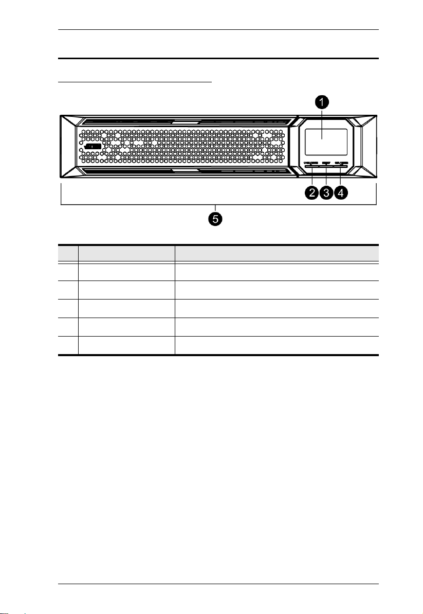
UPS Front View for all series
No. Component Description
1Display LCD
2 On / Mute Button Click this to turn on the LCD
3 Select Button Click this to jump to the next selection
Chapter 1. Introduction
4 Off / Enter Button Click this to turn off the LCD
5 Removable Front Panel
5
UPS User Manual
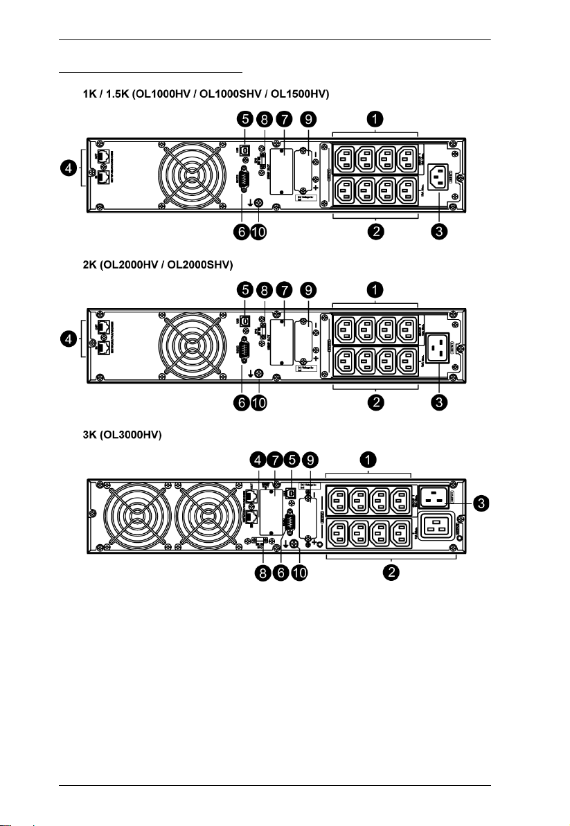
UPS HV Series Rear View
6
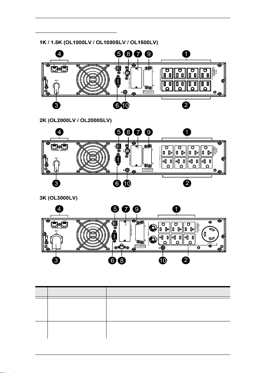
UPS LV Series Rear View
Chapter 1. Introduction
No. Component Description
1 Programmable Outlets For non-critical load connection. These outlets can be
programmed to provide backup power and surge
protection.
2 Backup and Surge
Protected Outlets
For critical load connection. These outlets provide
backup power and surge protection.
7

UPS User Manual
No. Component Description
3 AC Input For HV models, connect the included Power Cable
between this port and an AC power socket.
For LV models, this serves as a power cable. Connect
the power cable to an AC power socket.
4 Network / Fax / Modem
Surge Protection
5 USB Communication
Port
6 RS-232 Communication
Port
Protects standard RJ-45-based products (LAN lines)
and cabling systems from surges.
For scheduled UPS shutdown / start-up and status
monitoring.
For scheduled UPS shutdown / start-up and status
monitoring.
7 SNMP Intelligent Slot The UPS is equipped with intelligent slot perfect for
SNMP. When installing SNMP in the UPS, it will
provide advanced communication and monitoring
options.
8 Emergency Power Off
Function Connector
Enables an emergency UPS Power Off from a remote
location.
(EPO)
9 External Battery
Connection Port
This port connects to external battery pack for backup
power. For external battery pack, please refer to
Battery Information on page x.
10 Grounding Terminal Connect to a suitable grounding object.
8
Chapter 2
1. Important safety information regarding the placement of
this device is provided on Safety Instruction s on page 49.
Please review it before proceeding.
2. Make sure that power to all the devices you will be
installing has been turned off. You must unplug the power
cords of any computers that have the Keyboard Power On
Hardware Setup
Mounting
The unit can be either desktop mounted (vertically or horizontally) or
rack mounted (in a 19” rack chassis).
Rack Mount
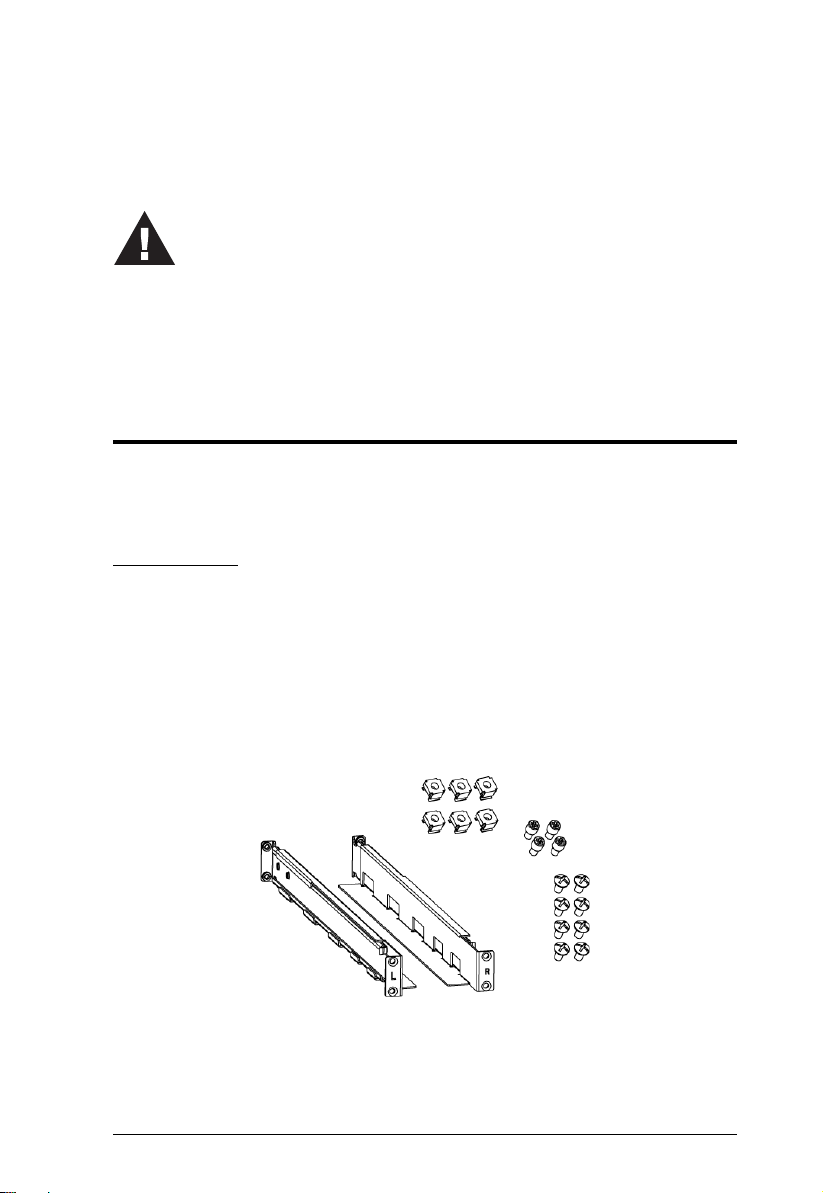
A rail slide kit and rack mounting kit is provided in the package for rack
mounting. The rail slide kit is installed on the rack and the rack mounting
kit installs the UPS to the rack. To mount the UPS, do the following:
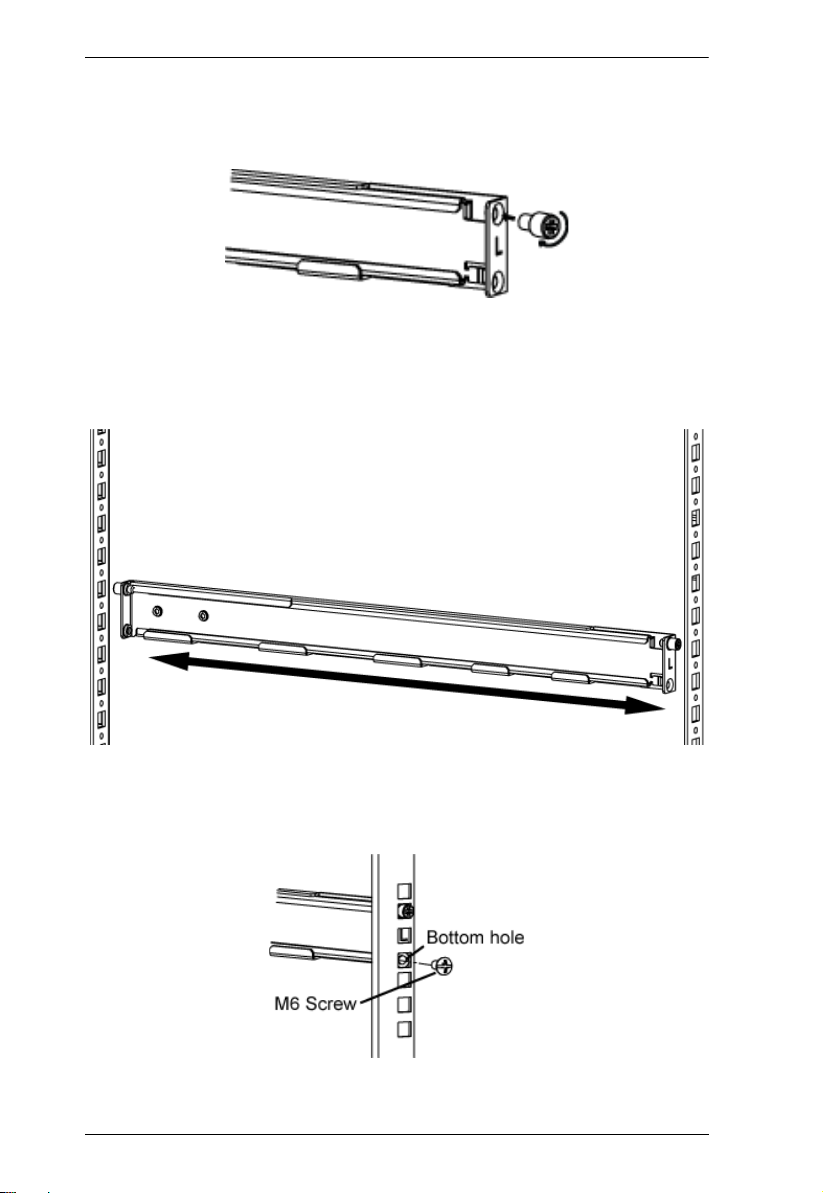
1. Make sure the rail slide kit includes all the components. The
components include 2 slide rails (1 for each side, indicated by L and
R in the diagram below), 6 M6 nuts, 4 fixing studs and 8 M6 screws,
as shown in the diagram below:
9
UPS User Manual
2. Insert the 4 fixing studs: Two screw holes are available on both
ends of a slide rail. Screw a fixing stud into the top screw hole as
shown:
3. Have the rail near the supporting columns, pull the two ends of the
rail slider apart. While at it, fit the fixing studs into the columns’
holes on the same level. This step serves to hold the slider rail in
place for the latter steps.
4. Screw a M6 screw into each of the bottom holes to fix the rail slider
in place for both ends of the rail, and for both rail sliders (a total of 4
M6 screws are used here).
10
Chapter 2. Hardware Setup
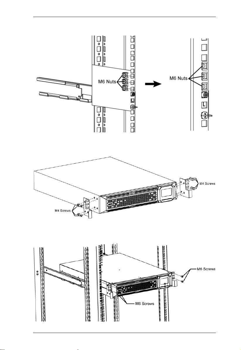
5. Insert the M6 nuts onto the support columns as show below:
6. Attach the mounting kit onto the UPS by screwing M4 screws into
the mounting kit screw holes and the UPS as shown:
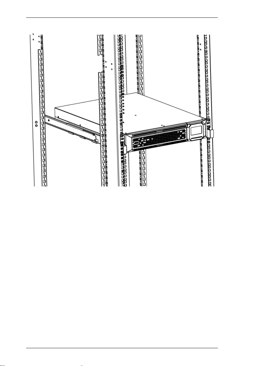
7. Fit the UPS onto the rack rails and stabilize the mounting kit (M6
screws) onto the rack as shown:
11
UPS User Manual
12
 Loading...