

User Manual
CS-138A

Note: This equipment has been tested and found to comply with
the limits for a Class B digital device, pursuant to Part 15 of the
FCC Rules. These limits are designed to provide reasonable
protection against harmful interference in a residential installation.
This equipment generates, uses and can radiate radio frequency
energy, and if not installed and used in accordance with the
instruction manual, may cause interference to radio
communications. However, there is no guarantee that
interference will not occur in a particular installation. If this
equipment does cause harmful interference to radio or television
reception, which can be determined by turning the equipment off
and on, the user is encouraged to try to correct the interference
by one or more of the following measures:
M Reorient or relocate the receiving antenna;
M Increase the separation between the equipment and receiver;
M Connect the equipment into an outlet on a circuit different from
that which the receiver is connected;
M Consult the dealer or an experienced radio/television technician for
help.

Packing List
The complete Master View CS-138A package consists of:
M One CS-138A KVM Switch
M One Power Adapter
M One User Manual
Check to make sure that the unit was not damaged in shipping. If you encounter
a problem, contact your dealer.
Read this manual thoroughly and follow the installation and operation
procedures carefully to prevent any damage to the unit, and/or any of the
devices connected to it.
© Copyright 2001 ATEN® International Co., Ltd.
Manual Part No. PAPE-0115-400
Printed in Taiwan 03/2000
All brand names and trademarks are the registered property of their respective owners.
CS-138A User Manual iii.

Contents
Overview . . . . . . . . . . . . . . . . . . . . . . . . . . . . . . . . . . . . . . . . . . . . . . . . . . . . . . 1
Features. . . . . . . . . . . . . . . . . . . . . . . . . . . . . . . . . . . . . . . . . . . . . . . . . . . . . . . 2
Hardware Requirements . . . . . . . . . . . . . . . . . . . . . . . . . . . . . . . . . . . . . . . . . . 3
Console . . . . . . . . . . . . . . . . . . . . . . . . . . . . . . . . . . . . . . . . . . . . . . . . . . . . 3
Computer . . . . . . . . . . . . . . . . . . . . . . . . . . . . . . . . . . . . . . . . . . . . . . . . . . . 3
Cables . . . . . . . . . . . . . . . . . . . . . . . . . . . . . . . . . . . . . . . . . . . . . . . . . . . . . 4
Introduction . . . . . . . . . . . . . . . . . . . . . . . . . . . . . . . . . . . . . . . . . . . . . . . . . . . . 5
Front View . . . . . . . . . . . . . . . . . . . . . . . . . . . . . . . . . . . . . . . . . . . . . . . . . . 5
Rear View. . . . . . . . . . . . . . . . . . . . . . . . . . . . . . . . . . . . . . . . . . . . . . . . . . . 6
Installation . . . . . . . . . . . . . . . . . . . . . . . . . . . . . . . . . . . . . . . . . . . . . . . . . . . . . 7
Before you Begin . . . . . . . . . . . . . . . . . . . . . . . . . . . . . . . . . . . . . . . . . . . . . 7
Single Station Installation. . . . . . . . . . . . . . . . . . . . . . . . . . . . . . . . . . . . . . . 7
Two Stage Installation . . . . . . . . . . . . . . . . . . . . . . . . . . . . . . . . . . . . . . . . . 8
Three Stage Installation. . . . . . . . . . . . . . . . . . . . . . . . . . . . . . . . . . . . . . . . 9
Operation. . . . . . . . . . . . . . . . . . . . . . . . . . . . . . . . . . . . . . . . . . . . . . . . . . . . . 11
Hot Plugging. . . . . . . . . . . . . . . . . . . . . . . . . . . . . . . . . . . . . . . . . . . . . . . . 11
Powering Off and Restarting . . . . . . . . . . . . . . . . . . . . . . . . . . . . . . . . . . . 12
Port Selection. . . . . . . . . . . . . . . . . . . . . . . . . . . . . . . . . . . . . . . . . . . . . . . 12
Port ID Numbering. . . . . . . . . . . . . . . . . . . . . . . . . . . . . . . . . . . . . . . . . . . . . . 14
Hotkey Summary Table . . . . . . . . . . . . . . . . . . . . . . . . . . . . . . . . . . . . . . . 15
OSD Operation . . . . . . . . . . . . . . . . . . . . . . . . . . . . . . . . . . . . . . . . . . . . . . . . 16
OSD Hotkey Navigation. . . . . . . . . . . . . . . . . . . . . . . . . . . . . . . . . . . . . . . 16
OSD Overview . . . . . . . . . . . . . . . . . . . . . . . . . . . . . . . . . . . . . . . . . . . . . . 17
OSD Navigation . . . . . . . . . . . . . . . . . . . . . . . . . . . . . . . . . . . . . . . . . . . . . 18
OSD Main Menu Headings . . . . . . . . . . . . . . . . . . . . . . . . . . . . . . . . . . . . 18
The Function Keys: . . . . . . . . . . . . . . . . . . . . . . . . . . . . . . . . . . . . . . . . . . 19
Factory Default Settings. . . . . . . . . . . . . . . . . . . . . . . . . . . . . . . . . . . . . . . 23
OSD Security . . . . . . . . . . . . . . . . . . . . . . . . . . . . . . . . . . . . . . . . . . . . . . . 24
Appendix . . . . . . . . . . . . . . . . . . . . . . . . . . . . . . . . . . . . . . . . . . . . . . . . . . . . . 25
Master View - Computer Connection Table. . . . . . . . . . . . . . . . . . . . . . . . 25
Troubleshooting . . . . . . . . . . . . . . . . . . . . . . . . . . . . . . . . . . . . . . . . . . . . . 26
Specifications. . . . . . . . . . . . . . . . . . . . . . . . . . . . . . . . . . . . . . . . . . . . . . . 27
Limited Warranty . . . . . . . . . . . . . . . . . . . . . . . . . . . . . . . . . . . . . . . . . . . . 28
iv. CS-138A User Manual

Overview
The Master View CS-138A KVM Switch is a control unit that allows access to
multiple computers from a single console (keyboard, monitor, and mouse).
Before the development of the Master View, the only way to control multiple
computer configurations from a single console was through a complex and
costly network. Now, with the Master View CS-138A, you can easily access
multiple computers in a cost effective manner.
A single Master View CS-138A can control up to 8 computers. Since units can
be cascaded to three levels, in a full three stage installation up to 73 CS-138A
Master View switches can control up to 512 computers - all from a single
console.
Setup is fast and easy; plugging cables into their appropriate ports is all that is
entailed. There is no software to configure, so there is no need to get involved in
complex installation routines or be concerned with incompatibility problems.
Since the CS-138A intercepts keyboard input directly, it works on any hardware
platform and with all operating computers.
There are three convenient methods to access any computer connected to the
installation: (1) using the pushbutton port selection switches located on each
unit’s front panel; (2) entering Hotkey combinations from the keyboard; and (3)
selecting from menus provided by the On Screen Display (OSD) feature. A
powerful Quick View Scan feature also permits auto scanning and monitoring
the activities of all computers running on the installation one by one.
There is no better way to save time and money than with a Master View
CS-138A installation. By allowing a single console to manage all the attached
computers, a Master View CS-138A installation: (1) eliminates the expense of
having to purchase a separate keyboard, monitor, and mouse for each
computer; (2) saves all the space those extra components would take up; (3)
saves on energy costs; and (4) eliminates the inconvenience and wasted effort
involved in constantly moving from one computer to another.
CS-138A User Manual 1

Features
M Cascadable To Three Levels - Control Up to 512 Computers From a Single
Console
M No Software Required - Computer Selection via Front Panel Switches,
Hotkeys, or On Screen Display (OSD)
M Quick View Scan Feature for Monitoring User-Selected computers
M PS/2 and Serial Mouse Emulation Provided For System Bootup
M PS/2 Compatible Mouse Support - Microsoft Intellimouse Explorer and
Logitech FirstMouse+ Support*
M SVGA, VGA, abd Multisync Monitor Support
M Superior Video Quality: Up to 1920x1440; DDC; DDC2; DDC2B
M LED Display for Easy Status Monitoring
M Supports High Quality CS Series Custom KVM Cables
M Rack Mountable in 19" computer Rack (1U)
M Hot Pluggable, Add or Remove Computers without Powering Off the Switch
* 1. PS/2 compatible mouse support is for three button (wheel) mice.
2. The Logitech Mouse Ware program’s Change Device procedure does
not work on Microsoft NT systems.
2 CS-138A User Manual

Hardware Requirements
Console
M A VGA, SVGA, or Multisync monitor capable of the highest resolution that
you will be using on any computer in the installation.
M A PS/2 style mouse
M A PS/2 style keyboard
Computer
The following equipment must be installed on each computer:
M A VGA, SVGA or Multisync card.
M Either a 6-pin mini-DIN (PS/2 style), or DB-9 (standard serial), mouse port.
M Either a 6-pin mini-DIN (PS/2 Style) keyboard port with +5V DC on pin 4 and
Ground on pin 3, or a 5-pin DIN (AT Style) keyboard port with +5V DC on pin
5 and ground on pin 4.*
* See the note under Cables in the next section.
CS-138A User Manual 3

Cables
Use of substandard cables may damage the connected devices or degrade overall
performance. For optimum signal integrity and to simplify the layout, we strongly
recommend that you use the following high quality CS Custom Cable sets:
Connector Purpose CS Cable Part Number
AT (5 pin DIN) Keyboard and Serial Mouse 2L-1001P/C (1.8m) or
PS/2 (6 pin mini-DIN) Keyboard and Mouse
Cascading Master Views
Note: 1. If your computer uses a standard AT style keyboard socket you will
need to purchase a PS/2-to-AT keyboard adapter (Part No. 2A-106,
or any standard keyboard adapter).
2. If your computer uses a standard 9 pin serial port for the mouse, you
will need to purchase a special PS/2-to-Serial mouse adapter (Part
No. 2A-105); a standard mouse adapter will probably not work).
3. Because of the wiring and pin assignments, you cannot use a
Serial-to-PS/2 adapter at the end that plugs into the CS-138A.
Attempting to use a standard serial extender cable with adapters at
both ends will fail.
2L-1003P/C (3m)
4 CS-138A User Manual
Introduction
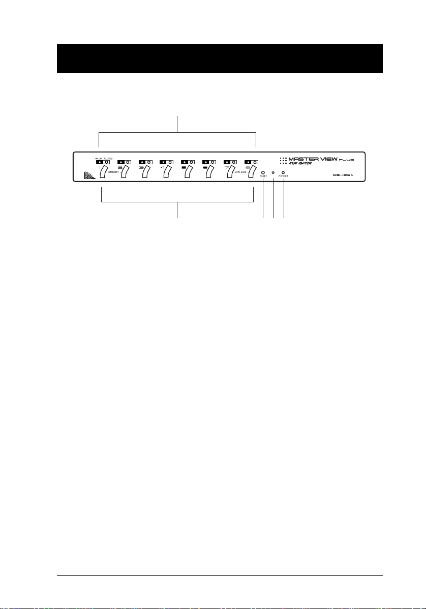
Front View
1
2
1. Port LEDs
The Port LEDs provide status information about their corresponding CPU
Ports. They come in pairs - one pair for each Port. The one on the left is the
On Line LED; the one on the right is the Selected Port LED:
M The On Line LEDs light ORANGE to indicate that the computer attached
to its corresponding port is up and running. If the LED is flashing, it indicates that the Port is being used for cascading to another Master View
switch (see p. 8).
M A Selected LED lights GREEN to indicate that the computer attached to its
corresponding port is the one that has the KVM focus. The LED is steady
under normal conditions, but flashes when its port is accessed under Auto
Scan Mode (see p. 30).
2. Port Selection Switches
Press a switch to access the computer attached to the corresponding port.
M Pressing Buttons 1 and 2 simultaneously for 3 seconds performs a Key-
board and Mouse Reset.
M Pressing 7 and 8 simultaneously starts Auto Scan Mode (see p. 30).
3. Reset
Use a thin object (such as the end of a paper clip, or a ballpoint pen), to
press this recessed switch in to initiate a warm reset. If the switch is kept in
for longer than three seconds, a cold reset takes place.
4. Sound Opening
System sounds (beeps, etc.), are emitted from this opening.
5. Power LED
Lights to indicate that the unit is receiving power.
3 4 5
CS-138A User Manual 5
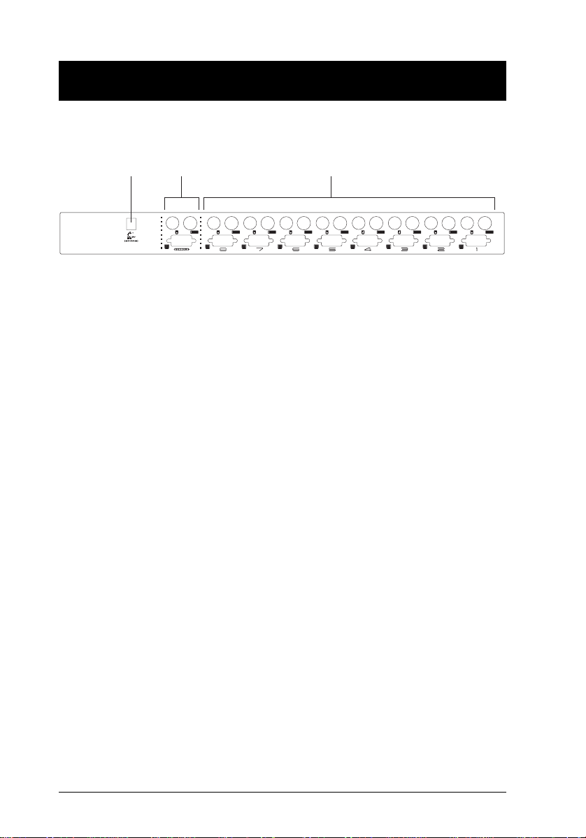
Rear View
1
23
1. Power Jack
The unit is designed to be non-powered (external power is not required - its
operating power comes from the computers). In general, the only time that
external power is necessary is when you cascade it, or if operation becomes
erratic because the unit isn’t obtaining enough power from the computer
connections. If you choose to use external power, the power adapter cable
plugs in here.
2. Console Port Section
M If this is a first station unit, your monitor, keyboard and mouse plug in here.
M If this is a daisy chained unit, the cables that link back to a port on a higher
Master View unit plug in here.
3. CPU Port Section
The cables that link to the computers plug in here.
6 CS-138A User Manual
 Loading...