


4 Port KVM Switch
User Manual
CS-124U
2001-04-25

NOTE: This equipment has been tested and found to comply with the limits
for a Class B digital device pursuant to Subpart J of Part 15 of the FCC Rules.
These limits are designed to provide reasonable protection against harmful
interference in a residential installation. This equipment generates, uses and
can radiate radio frequency energy and, if not installed and used in
accordance with the instructions, may cause harmful interference to radio
communications. However, there is no guarantee that interference will not
occur in a particular installation. If this equipment does cause harmful
interference to radio or television reception, which can be determined by
turning the equipment off and on, the user is encouraged to try to correct the
interference by one or more of the following measures:
w Reorient or relocate the receiving antenna.
w Increase the separation between the equipment and receiver.
w Connect the equipment into an outlet on a circuit different from that which
the receiver is connected.
w Consult the dealer or an experienced radio/television technician for help.
2001-04-25

Packing List
The complete Master View CS-124U package consists of:
One CS-124U KVM Switch
w
One Power Adapter
w
One User Manual
w
Check to make sure that the unit was not damaged in shipping. If you encounter
a problem, contact your dealer.
Read this manual thoroughly and follow the installation and operation
procedures carefully to prevent any damage to the unit, and/or any of the
devices connected to it.
©Copyright 2001 ATEN International Co., Ltd.
Manual Part No. PAPE-0184-100
Printed in Taiwan 04/2001
All brand names and trademarks are the registered property of their respective owners.
CS-124U User Manual iii.
2001-04-25

Contents
Overview . . . . . . . . . . . . . . . . . . . . . . . . . . . . . . . . . . . . . . . . . . . . . . . . . . . . . . 1
Features. . . . . . . . . . . . . . . . . . . . . . . . . . . . . . . . . . . . . . . . . . . . . . . . . . . . . . . 2
Hardware Requirements . . . . . . . . . . . . . . . . . . . . . . . . . . . . . . . . . . . . . . . . . . 3
Console . . . . . . . . . . . . . . . . . . . . . . . . . . . . . . . . . . . . . . . . . . . . . . . . . . . . 3
PC . . . . . . . . . . . . . . . . . . . . . . . . . . . . . . . . . . . . . . . . . . . . . . . . . . . . . . . . 3
Cables . . . . . . . . . . . . . . . . . . . . . . . . . . . . . . . . . . . . . . . . . . . . . . . . . . . . . 3
Introduction . . . . . . . . . . . . . . . . . . . . . . . . . . . . . . . . . . . . . . . . . . . . . . . . . . . . 4
Front View . . . . . . . . . . . . . . . . . . . . . . . . . . . . . . . . . . . . . . . . . . . . . . . . . . 4
Rear View. . . . . . . . . . . . . . . . . . . . . . . . . . . . . . . . . . . . . . . . . . . . . . . . . . . 5
Installation . . . . . . . . . . . . . . . . . . . . . . . . . . . . . . . . . . . . . . . . . . . . . . . . . . . . . 6
Before you Begin . . . . . . . . . . . . . . . . . . . . . . . . . . . . . . . . . . . . . . . . . . . . . 6
Single Station Installation. . . . . . . . . . . . . . . . . . . . . . . . . . . . . . . . . . . . . . . 6
Second Station Installation . . . . . . . . . . . . . . . . . . . . . . . . . . . . . . . . . . . . . 7
Third Station Installation . . . . . . . . . . . . . . . . . . . . . . . . . . . . . . . . . . . . . . . 9
Operation. . . . . . . . . . . . . . . . . . . . . . . . . . . . . . . . . . . . . . . . . . . . . . . . . . . . . 11
Hot Plugging. . . . . . . . . . . . . . . . . . . . . . . . . . . . . . . . . . . . . . . . . . . . . . . . 11
Powering Off and Restarting . . . . . . . . . . . . . . . . . . . . . . . . . . . . . . . . . . . 12
Port Selection. . . . . . . . . . . . . . . . . . . . . . . . . . . . . . . . . . . . . . . . . . . . . . . 13
Port ID Numbering. . . . . . . . . . . . . . . . . . . . . . . . . . . . . . . . . . . . . . . . . . . . . . 14
ID Numbering Overview. . . . . . . . . . . . . . . . . . . . . . . . . . . . . . . . . . . . . . . 14
Port Key In Examples . . . . . . . . . . . . . . . . . . . . . . . . . . . . . . . . . . . . . . . . 15
Hotkey Summary Table . . . . . . . . . . . . . . . . . . . . . . . . . . . . . . . . . . . . . . . 16
OSD Operation . . . . . . . . . . . . . . . . . . . . . . . . . . . . . . . . . . . . . . . . . . . . . . . . 17
OSD Overview . . . . . . . . . . . . . . . . . . . . . . . . . . . . . . . . . . . . . . . . . . . . . . 17
OSD Navigation . . . . . . . . . . . . . . . . . . . . . . . . . . . . . . . . . . . . . . . . . . . . . 18
OSD Main Menu Headings . . . . . . . . . . . . . . . . . . . . . . . . . . . . . . . . . . . . 19
The Function Keys. . . . . . . . . . . . . . . . . . . . . . . . . . . . . . . . . . . . . . . . . . . 19
Factory Default Settings. . . . . . . . . . . . . . . . . . . . . . . . . . . . . . . . . . . . . . . 24
OSD Security . . . . . . . . . . . . . . . . . . . . . . . . . . . . . . . . . . . . . . . . . . . . . . . 24
Appendix . . . . . . . . . . . . . . . . . . . . . . . . . . . . . . . . . . . . . . . . . . . . . . . . . . . . . 25
Troubleshooting . . . . . . . . . . . . . . . . . . . . . . . . . . . . . . . . . . . . . . . . . . . . . 26
Specifications. . . . . . . . . . . . . . . . . . . . . . . . . . . . . . . . . . . . . . . . . . . . . . . 27
Limited Warranty . . . . . . . . . . . . . . . . . . . . . . . . . . . . . . . . . . . . . . . . . . . . 28
iv. CS-124U User Manual
2001-04-25

Overview
The Master View Plus CS-124U represents a revolutionary new direction in
KVM (Keyboard, Video, Mouse) Switches. The CS-124U is a control unit that
allows access to four computer systems from a single USB keyboard, USB
mouse, and monitor console in a cost effective manner. There are three
convenient methods to access the computers: (1) push button port selection
switches located on the unit’s front panel; (2) Hotkey combinations; and (3)
selecting from menus provided by the OSD (On Screen Display) feature. A
powerful Quick View Scan feature also allows you to autoscan and monitor the
activities of all operating computers on the installation one by one. Setup is fast
and easy; simply plug cables into their appropriate ports. There is no software to
configure, no installation routines, and no incompatibility problems. Since the
CS-124U intercepts keyboard input directly, it works on any hardware platform
and with all operating systems.
The CS-124U represents the second generation of KVM switches incorporating
USB technology to handle the keyboard and mouse data connection between
itself and the connected computers.
There is no better way to save time and money than with a Master View
CS-124U installation. Since a single console manages all of the computers, the
CS-124U setup: eliminates the expense of having to purchase a separate
keyboard, monitor, and mouse for each computer; saves all the space those
extra components would take up; saves on energy costs; and eliminates the
inconvenience and wasted effort involved in constantly moving around from one
computer to another.
CS-124U User Manual 1
2001-04-25

Features
Full Speed Connectivity - USB Mouse and Keyboard
w
Easy Installation
w
No Software Required - Computer Selection via Front Panel Switches, Hot
w
Keys, or OSD (On Screen Display)
New and Improved OSD Interface for Easier Control of Your Computers
w
LED Display For Easy Status Monitoring
w
Quick View Scan Feature for Monitoring Selected Computers
w
Complete Keyboard and Mouse Emulation for Error Free Booting
w
Superior Video Quality; 1920x1440; DDC; DDC2; DDC2B
w
Hot Pluggable - Add or Remove Computers for Maintenance Without
w
Powering Down the Switch
Supports Mac Keyboard Power On / Off Function
w
Supports High Quality CS Connector Cables
w
Rack Mountable (with optional Rack Panel; Part No.2X-007)
w
2 CS-124U User Manual
2001-04-25

Hardware Requirements
Console
A VGA, SVGA, or Multisync monitor capable of the highest resolution that
w
you will be using on any computer in the installation.
A USB mouse
w
A USB keyboard
w
Computer
The following equipment must be installed on each computer:
A VGA, SVGA or Multisync card.
w
USB Type A port.
w
Cables
Use of substandard cables may damage the connected devices or degrade
overall performance. For optimum signal integrity and to simplify the layout, we
strongly recommend that you use the following high quality CS cables:
2L-1201U (1.2M) or 2L-1202U (1.8m).
CS-124U User Manual 3
2001-04-25
Introduction
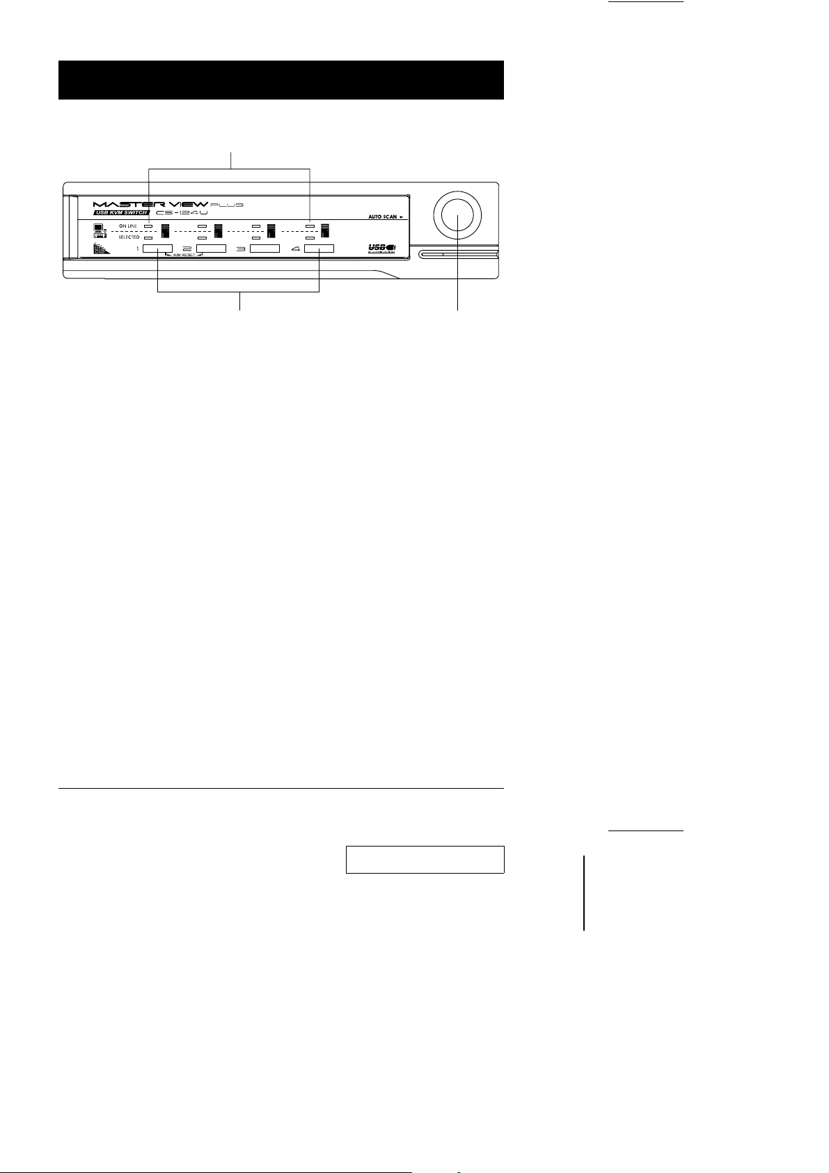
Front View
1
2 3
1. Port LEDs
The selected LEDs light to indicate the currently selected port.
On Line: Lights ORANGE to indicate that the computer attached to the
corresponding port is up and running. If the LED is flashing, it
indicates that the Port is being used for Cascading to another
Master View switch.
Selected: Lights GREEN to indicate the currently selected port. The LED is
steady under normal conditions, but flashes when its port is
accessed under Auto Scan mode.
2. Port Selection Switches
w Press a switch to access the computer attached to the corresponding
port.
w Pressing Buttons 1 and 2 simultaneously for 3 seconds performs a Key-
board and Mouse reset (K/M Reset).
3. Auto Scan Switch
w Press this switch again to activate Auto Scanning. To stop, press it
again, or press the keyboard’s Spacebar.
4 CS-124U User Manual
2001-04-25

Rear View
1 2 3
1. Power Jack
The unit is designed to use external power, the power adapter cable plugs in
here.
2. Console Port Section
Your monitor, keyboard and mouse plug in here.
3. CPU Port Section
The cables that link to the computers plug in here.
CS-124U User Manual 5
2001-04-25

Installation
Before you Begin
1. Make sure that power to all the devices you will be connecting
up have been turned off. You must unplug the power cords of
any computers that have the Keyboard Power On function.
Otherwise, the switch will receive power from the computer.
2. To prevent damage to your equipment due to ground potential
difference, make sure that all devices on the installation are
properly grounded. Consult your dealer for technical details, if
necessary.
Single Station Installation
In a Single Stage installation, there are no additional Master View’s daisy
chained down from the first unit. To set up a single stage installation do the
following:
1. Plug your keyboard, mouse, and monitor into the unit’s Console Ports.
2. In a Single Stage Installation, computers connect to all of the Master View’s
CPU ports (1 - 4). Use connector cable sets (as described in the Hardware
Requirements section), to connect the monitor and any available USB (type
A) port of the computer to any CS-124U CPU port.
3. The unit is designed to use external power, plug the adapter cable into the
Master View’s Power Jack, then plug the power adapter into an AC power
source.
6 CS-124U User Manual
2001-04-25