

KVM over IP Console Station
KA8270 / KA8278 / KA8280 / KA8288
User Manual
www.aten.com

KVM over IP Console Station User Manual
EMC Information
FEDERAL COMMUNICATIONS COMMISSION INTERFERENCE
ST
ATEMENT: This equipment has been tested and found to comply
with the limits for a Class A digital device, pursuant to Part 15 of the FCC
Rules. These limits are designed to provide reasonable protection
against harmful interference when the equipment is operated in a
commercial environment. This equipment generates, uses, and can
radiate radio frequency energy and, if not installed and used in
accordance with the instruction manual, may cause harmful
interference to radio communications. Operation of this equipment in a
residential area is likely to cause harmful interference in which case the
user will be required to correct the interference at his own expense.
The device complies with Part 15 of the FCC Rules. Operation is subject
to the following two conditions: (1) this device may not cause harmful
interference, and (2) this device must accept any interference received,
including interference that may cause undesired operation.
FCC Caution: Any changes or modifications not expressly approved by
the party responsible for compliance could void the user's authority to
operate this equipment.
Warning: Operation of this equipment in a residential environment
could cause radio interference.
KCC Statement
이 기기는 업무용 (A 급 ) 전자파 적합기기로서 판매자 또는 사용자는 이
점을 주의하시기 바라며 , 가정외의 지역에서 사용하는 것을 목적으로
합니다 .
RoHS
This product is RoHS compliant.
ii

KVM over IP Console Station User Manual
User Information
Online Registration
Be sure to register your product at our online support center:
International http://eservice.aten.com
Telephone Support
For telephone support, call this number:
International 886-2-8692-6959
China 86-400-810-0-810
Japan 81-3-5615-5811
Korea 82-2-467-6789
North America 1-888-999-ATEN ext 4988
1-949-428-1111
User Notice
All information, documentation, and specifications contained in this
manual are subject to change without prior notification by the
manufacturer. The manufacturer makes no representations or
warranties, either expressed or implied, with respect to the contents
hereof and specifically disclaims any warranties as to merchantability or
fitness for any particular purpose. Any of the manufacturer's software
described in this manual is sold or licensed as is. Should the programs
prove defective following their purchase, the buyer (and not the
manufacturer, its distributor, or its dealer), assumes the entire cost of all
necessary servicing, repair and any incidental or consequential
damages resulting from any defect in the software.
The manufacturer of this system is not responsible for any radio and/or
TV interference caused by unauthorized modifications to this device. It
is the responsibility of the user to correct such interference.
The manufacturer is not responsible for any damage incurred in the
operation of this system if the correct operational voltage setting was
not selected prior to operation. PLEASE VERIFY THAT THE VOLTAGE
SETTING IS CORRECT BEFORE USE.
iii

KVM over IP Console Station User Manual
Copyright © 2018 ATEN® International Co., Ltd.
Manual Date: 2018-08-24
Altusen and the ATEN logo are registered trademarks of ATEN International Co., Ltd. All rights reserved. All
other brand names and trademarks are the registered property of their respective owners.
Package Contents
1 KVM over IP Console Station (KA8270 or KA8278 or KA8280 or
KA8288)
1 Power Adapter
1 Power Cord
1 Mounting Kit
1 Foot Pad Set (4 pcs.)
1 User Instructions*
* Features may have been added to the KVM over IP console station
since the user instructions were created. Please visit our website to
download the most up-to-date version of the user manual.
Check to make sure that all of the components are present and in good order.
If anything is missing, or was damaged in shipping, contact your dealer. Read
this manual thoroughly and follow the installation and operation procedures
carefully to prevent any damage to the KVM over IP console station or to any
other devices on the installation.
iv

KVM over IP Console Station User Manual
Contents
EMC Information . . . . . . . . . . . . . . . . . . . . . . . . . . . . . . . . . . . . . . . . . . . . . ii
User Information . . . . . . . . . . . . . . . . . . . . . . . . . . . . . . . . . . . . . . . . . . . . .iii
Online Registration . . . . . . . . . . . . . . . . . . . . . . . . . . . . . . . . . . . . . . . .iii
Telephone Support . . . . . . . . . . . . . . . . . . . . . . . . . . . . . . . . . . . . . . . .iii
User Notice . . . . . . . . . . . . . . . . . . . . . . . . . . . . . . . . . . . . . . . . . . . . . .iii
Package Contents. . . . . . . . . . . . . . . . . . . . . . . . . . . . . . . . . . . . . . . . . . . iv
Contents . . . . . . . . . . . . . . . . . . . . . . . . . . . . . . . . . . . . . . . . . . . . . . . . . . . v
About This Manual . . . . . . . . . . . . . . . . . . . . . . . . . . . . . . . . . . . . . . . . . .viii
Conventions . . . . . . . . . . . . . . . . . . . . . . . . . . . . . . . . . . . . . . . . . . . . ix
Product Information. . . . . . . . . . . . . . . . . . . . . . . . . . . . . . . . . . . . . . . . . . ix
Chapter 1.Introduction
Overview . . . . . . . . . . . . . . . . . . . . . . . . . . . . . . . . . . . . . . . . . . . . . . . . . . .1
Features . . . . . . . . . . . . . . . . . . . . . . . . . . . . . . . . . . . . . . . . . . . . . . . . . . .2
Requirements . . . . . . . . . . . . . . . . . . . . . . . . . . . . . . . . . . . . . . . . . . . . . . . 2
Console . . . . . . . . . . . . . . . . . . . . . . . . . . . . . . . . . . . . . . . . . . . . . . . . .2
Components . . . . . . . . . . . . . . . . . . . . . . . . . . . . . . . . . . . . . . . . . . . . . . . . 3
Front View . . . . . . . . . . . . . . . . . . . . . . . . . . . . . . . . . . . . . . . . . . . . . . .3
Rear View . . . . . . . . . . . . . . . . . . . . . . . . . . . . . . . . . . . . . . . . . . . . . . .4
Chapter 2.Hardware Setup
Overview . . . . . . . . . . . . . . . . . . . . . . . . . . . . . . . . . . . . . . . . . . . . . . . . . . .5
Before You Begin . . . . . . . . . . . . . . . . . . . . . . . . . . . . . . . . . . . . . . . . . . . . 5
Mounting . . . . . . . . . . . . . . . . . . . . . . . . . . . . . . . . . . . . . . . . . . . . . . . . . . . 6
Rack Mounting . . . . . . . . . . . . . . . . . . . . . . . . . . . . . . . . . . . . . . . . . . .6
Wall Mounting . . . . . . . . . . . . . . . . . . . . . . . . . . . . . . . . . . . . . . . . . . . . 7
Single Stage Installation . . . . . . . . . . . . . . . . . . . . . . . . . . . . . . . . . . . . . . .8
Hot Plugging . . . . . . . . . . . . . . . . . . . . . . . . . . . . . . . . . . . . . . . . . . . . . . . .9
Powering Off and Restarting. . . . . . . . . . . . . . . . . . . . . . . . . . . . . . . . . . .10
Chapter 3.Operation
Overview . . . . . . . . . . . . . . . . . . . . . . . . . . . . . . . . . . . . . . . . . . . . . . . . . .11
Logging In . . . . . . . . . . . . . . . . . . . . . . . . . . . . . . . . . . . . . . . . . . . . . . . . .11
Dashboard. . . . . . . . . . . . . . . . . . . . . . . . . . . . . . . . . . . . . . . . . . . . . . . . . 13
Page Components. . . . . . . . . . . . . . . . . . . . . . . . . . . . . . . . . . . . . . . .13
Dashboard Operation . . . . . . . . . . . . . . . . . . . . . . . . . . . . . . . . . . . . . . . . 15
Monitor Unit Option . . . . . . . . . . . . . . . . . . . . . . . . . . . . . . . . . . . . . . .16
Primary / Secondary Display . . . . . . . . . . . . . . . . . . . . . . . . . . . . . 16
GUI . . . . . . . . . . . . . . . . . . . . . . . . . . . . . . . . . . . . . . . . . . . . . . . .17
Disconnect . . . . . . . . . . . . . . . . . . . . . . . . . . . . . . . . . . . . . . . . . . . 17
Reconnect . . . . . . . . . . . . . . . . . . . . . . . . . . . . . . . . . . . . . . . . . . . 17
Tab / Panel Array Display and Management . . . . . . . . . . . . . . . . . . . . . .18
Tab Options. . . . . . . . . . . . . . . . . . . . . . . . . . . . . . . . . . . . . . . . . . . . .18
Tab Display . . . . . . . . . . . . . . . . . . . . . . . . . . . . . . . . . . . . . . . . . .19
Panel Array Options . . . . . . . . . . . . . . . . . . . . . . . . . . . . . . . . . . . . . .19
v

KVM over IP Console Station User Manual
Panel Array Display. . . . . . . . . . . . . . . . . . . . . . . . . . . . . . . . . . . . 20
Tab / Panel Array Management . . . . . . . . . . . . . . . . . . . . . . . . . . . . . 21
Adding a Tab. . . . . . . . . . . . . . . . . . . . . . . . . . . . . . . . . . . . . . . . . . . . 22
Adding another Tab. . . . . . . . . . . . . . . . . . . . . . . . . . . . . . . . . . . . . . . 23
Editing a Tab. . . . . . . . . . . . . . . . . . . . . . . . . . . . . . . . . . . . . . . . . . . . 24
Deleting a Tab. . . . . . . . . . . . . . . . . . . . . . . . . . . . . . . . . . . . . . . . . . . 24
Chapter 4.Device Management
Overview. . . . . . . . . . . . . . . . . . . . . . . . . . . . . . . . . . . . . . . . . . . . . . . . . . 25
Device List. . . . . . . . . . . . . . . . . . . . . . . . . . . . . . . . . . . . . . . . . . . . . . 26
Search . . . . . . . . . . . . . . . . . . . . . . . . . . . . . . . . . . . . . . . . . . . . . . 26
Remove Device . . . . . . . . . . . . . . . . . . . . . . . . . . . . . . . . . . . . . . . 26
Adding Device . . . . . . . . . . . . . . . . . . . . . . . . . . . . . . . . . . . . . . . . . . . 27
Changing Device Access Right. . . . . . . . . . . . . . . . . . . . . . . . . . . . . . 28
Chapter 5.System Configuration
Overview. . . . . . . . . . . . . . . . . . . . . . . . . . . . . . . . . . . . . . . . . . . . . . . . . . 29
User Management . . . . . . . . . . . . . . . . . . . . . . . . . . . . . . . . . . . . . . . . . . 30
Users and Groups . . . . . . . . . . . . . . . . . . . . . . . . . . . . . . . . . . . . . . . . 30
Add User . . . . . . . . . . . . . . . . . . . . . . . . . . . . . . . . . . . . . . . . . . . . 31
Copy User . . . . . . . . . . . . . . . . . . . . . . . . . . . . . . . . . . . . . . . . . . . 33
Modify User . . . . . . . . . . . . . . . . . . . . . . . . . . . . . . . . . . . . . . . . . . 34
Delete User . . . . . . . . . . . . . . . . . . . . . . . . . . . . . . . . . . . . . . . . . . 34
Managing (Assigning) Users and Groups . . . . . . . . . . . . . . . . . . . . . . 35
Using User Configuration Page. . . . . . . . . . . . . . . . . . . . . . . . . . . 35
Using Group Configuration Page . . . . . . . . . . . . . . . . . . . . . . . . . 36
Device Assignment . . . . . . . . . . . . . . . . . . . . . . . . . . . . . . . . . . . . . . . 38
Using Device Configuration Page . . . . . . . . . . . . . . . . . . . . . . . . . 38
Device Management. . . . . . . . . . . . . . . . . . . . . . . . . . . . . . . . . . . . . . . . . 41
Device Information . . . . . . . . . . . . . . . . . . . . . . . . . . . . . . . . . . . . . . . 41
Network . . . . . . . . . . . . . . . . . . . . . . . . . . . . . . . . . . . . . . . . . . . . . . . . 41
IP Installer . . . . . . . . . . . . . . . . . . . . . . . . . . . . . . . . . . . . . . . . . . . 42
IPv4 Settings . . . . . . . . . . . . . . . . . . . . . . . . . . . . . . . . . . . . . . . . . 43
IPv6 Settings . . . . . . . . . . . . . . . . . . . . . . . . . . . . . . . . . . . . . . . . . 44
Finishing Up . . . . . . . . . . . . . . . . . . . . . . . . . . . . . . . . . . . . . . . . . 44
ANMS . . . . . . . . . . . . . . . . . . . . . . . . . . . . . . . . . . . . . . . . . . . . . . . . . 44
RADIUS Settings. . . . . . . . . . . . . . . . . . . . . . . . . . . . . . . . . . . . . . 45
AD / LDAP Settings . . . . . . . . . . . . . . . . . . . . . . . . . . . . . . . . . . . . 46
Finishing Up . . . . . . . . . . . . . . . . . . . . . . . . . . . . . . . . . . . . . . . . . 47
Security . . . . . . . . . . . . . . . . . . . . . . . . . . . . . . . . . . . . . . . . . . . . . . . . 48
Login Failures . . . . . . . . . . . . . . . . . . . . . . . . . . . . . . . . . . . . . . . . 48
Account Policy. . . . . . . . . . . . . . . . . . . . . . . . . . . . . . . . . . . . . . . . 49
Working Mode . . . . . . . . . . . . . . . . . . . . . . . . . . . . . . . . . . . . . . . . 50
Finishing Up . . . . . . . . . . . . . . . . . . . . . . . . . . . . . . . . . . . . . . . . . 50
Maintenance . . . . . . . . . . . . . . . . . . . . . . . . . . . . . . . . . . . . . . . . . . . . . . . 51
Upgrade Main Firmware . . . . . . . . . . . . . . . . . . . . . . . . . . . . . . . . . . . 51
Firmware Upgrade Recovery . . . . . . . . . . . . . . . . . . . . . . . . . . . . . . . 53
vi

KVM over IP Console Station User Manual
Backup / Restore. . . . . . . . . . . . . . . . . . . . . . . . . . . . . . . . . . . . . . . . . 53
Backup. . . . . . . . . . . . . . . . . . . . . . . . . . . . . . . . . . . . . . . . . . . . . . 54
Restore . . . . . . . . . . . . . . . . . . . . . . . . . . . . . . . . . . . . . . . . . . . . .55
Push / Pull Configuration. . . . . . . . . . . . . . . . . . . . . . . . . . . . . . . . . . .56
Pull Configuration . . . . . . . . . . . . . . . . . . . . . . . . . . . . . . . . . . . . .57
Push Configuration . . . . . . . . . . . . . . . . . . . . . . . . . . . . . . . . . . . . 58
Terminal . . . . . . . . . . . . . . . . . . . . . . . . . . . . . . . . . . . . . . . . . . . . . . .59
System Operation . . . . . . . . . . . . . . . . . . . . . . . . . . . . . . . . . . . . . . . .60
Reset Default Values. . . . . . . . . . . . . . . . . . . . . . . . . . . . . . . . . . .60
Reset on exit:. . . . . . . . . . . . . . . . . . . . . . . . . . . . . . . . . . . . . . . . .60
Quick User Configuration . . . . . . . . . . . . . . . . . . . . . . . . . . . . . . . . . . . . .62
Chapter 6.Toolbar Interface
Overview . . . . . . . . . . . . . . . . . . . . . . . . . . . . . . . . . . . . . . . . . . . . . . . . . .63
Exit Remote Location . . . . . . . . . . . . . . . . . . . . . . . . . . . . . . . . . . . . .64
Video Settings . . . . . . . . . . . . . . . . . . . . . . . . . . . . . . . . . . . . . . . . . . . 65
Macros. . . . . . . . . . . . . . . . . . . . . . . . . . . . . . . . . . . . . . . . . . . . . . . . . 67
Hotkeys . . . . . . . . . . . . . . . . . . . . . . . . . . . . . . . . . . . . . . . . . . . . . 67
User Macros . . . . . . . . . . . . . . . . . . . . . . . . . . . . . . . . . . . . . . . . .69
Import / Export Macros . . . . . . . . . . . . . . . . . . . . . . . . . . . . . . . . .72
Delete Macros . . . . . . . . . . . . . . . . . . . . . . . . . . . . . . . . . . . . . . . . 73
Search Macros. . . . . . . . . . . . . . . . . . . . . . . . . . . . . . . . . . . . . . . . 73
System Macros . . . . . . . . . . . . . . . . . . . . . . . . . . . . . . . . . . . . . . .73
Further Configuration . . . . . . . . . . . . . . . . . . . . . . . . . . . . . . . . . . . . .74
Virtual Media . . . . . . . . . . . . . . . . . . . . . . . . . . . . . . . . . . . . . . . . .75
Message Board . . . . . . . . . . . . . . . . . . . . . . . . . . . . . . . . . . . . . . . 77
Mouse Sync Mode. . . . . . . . . . . . . . . . . . . . . . . . . . . . . . . . . . . . .79
Appendix
Safety Instructions. . . . . . . . . . . . . . . . . . . . . . . . . . . . . . . . . . . . . . . . . . .81
General . . . . . . . . . . . . . . . . . . . . . . . . . . . . . . . . . . . . . . . . . . . . . . . .81
Rack Mounting . . . . . . . . . . . . . . . . . . . . . . . . . . . . . . . . . . . . . . . . . .83
Consignes de sécurité. . . . . . . . . . . . . . . . . . . . . . . . . . . . . . . . . . . . . . . .85
Général . . . . . . . . . . . . . . . . . . . . . . . . . . . . . . . . . . . . . . . . . . . . . . . .85
Montage sur bâti . . . . . . . . . . . . . . . . . . . . . . . . . . . . . . . . . . . . . . . . .88
Technical Support . . . . . . . . . . . . . . . . . . . . . . . . . . . . . . . . . . . . . . . . . . .89
International. . . . . . . . . . . . . . . . . . . . . . . . . . . . . . . . . . . . . . . . . . . . . 89
North America . . . . . . . . . . . . . . . . . . . . . . . . . . . . . . . . . . . . . . . . . . .89
Specifications . . . . . . . . . . . . . . . . . . . . . . . . . . . . . . . . . . . . . . . . . . . . . . 90
Troubleshooting . . . . . . . . . . . . . . . . . . . . . . . . . . . . . . . . . . . . . . . . . . . .91
General Operation. . . . . . . . . . . . . . . . . . . . . . . . . . . . . . . . . . . . . . . . 91
Mouse Problems . . . . . . . . . . . . . . . . . . . . . . . . . . . . . . . . . . . . . . . . .92
Virtual Media . . . . . . . . . . . . . . . . . . . . . . . . . . . . . . . . . . . . . . . . . . . .93
Panel Array Mode . . . . . . . . . . . . . . . . . . . . . . . . . . . . . . . . . . . . . . . .93
Supported KVM Switches . . . . . . . . . . . . . . . . . . . . . . . . . . . . . . . . . . . . .94
Limited Warranty . . . . . . . . . . . . . . . . . . . . . . . . . . . . . . . . . . . . . . . . . . . . 95
vii

KVM over IP Console Station User Manual
About This Manual
This User Manual is provided to help you get the most from your KVM
over IP Console Station. It covers all aspects of installation,
configuration and operation. An overview of the information found in the
manual is provided below.
Chapter 1, Introduction, introduces you to the KVM over IP Console
Station. Its purpose, features and benefits are presented, and its front
and back panel components are described.
Chapter 2, Hardware Setup, provides step-by-step instructions for
setting up your installation, and explains some basic operation
procedures.
Chapter 3, Operation, explains the fundamental concepts involved in
operating the product, and provides a complete description of how to
operate the product.
Chapter 4, Device Management, explains how to add or remove KVM
over IP switches to or from the product.
Chapter 5, System Configuration, explains the system settings,
which include the General, ANMS, AD/LDAP, RADIUS, F/W Upgrade,
Backup/Restore, and explains the quick user interface.
Chapter 6, Toolbar Interface, explains how to use the toolbar
interface when entering a connected port.
An Appendix, at the end of the manual provides technical and
troubleshooting information.
viii

KVM over IP Console Station User Manual
Conventions
This manual uses the following conventions:
Monospaced Indicates text that you should key in.
[ ] Indicates keys you should press. For example, [Enter] means
to press the Enter key. If keys need to be chorded, they appear
together in the same bracket with a plus sign between them:
[Ctrl+Alt].
1. Numbered lists represent procedures with sequential steps.
♦ Bullet lists provide information, but do not involve sequential
steps.
→ Indicates selecting the option (on a menu or dialog box, for
example), that comes next. For example, Start
to open the Start menu, and then select Run.
Indicates critical information.
Product Information
→ Run means
For information about all ATEN products and how they can help you
connect without limits, visit ATEN on the Web or contact an ATEN
Authorized Reseller. Visit ATEN on the Web for a list of locations and
telephone numbers:
International http://www.aten.com
North America http://www.aten-usa.com
ix

KVM over IP Console Station User Manual
This Page Intentionally Left Blank
x

Chapter 1. Introduction
Chapter 1
Introduction
Overview
The KVM over IP Console Station (KA8270/KA8278/KA8280/KA8288)
is a standalone console that replaces PC or NB, enabling users to
remotely access, monitor and control all servers connected to multiple
ATEN’s KVM over IP switches* with impenetrable security against virus
threats. It also supports various data encryption methods, ensuring
impervious data protection. The KVM over IP Console Station can be
deployed anywhere instant access is needed and stringent security
required, ideal for applications such as studios, offices, data centers,
broadcast stations, control rooms, or network operations centers
(NOC).
All the KA8270, KA8278, KA8280, and KA8288 support USB mouse/
keyboard and two USB ports for Virtual Media function, and
respectively support 1 VGA video output, 1 VGA plus 1 HDMI video
outputs, 1 HDMI video output, and 2 HDMI video outputs at resolutions
up to 1920 x 1200 @ 60 Hz. With KA8278 and KA8288, users can
multitask across two displays with a single keyboard and mouse.
In addition, the KVM over IP Console Station provides Panel Array
Mode™ function, enabling administrators to monitor the video output of
up to 64 servers simultaneously. The feature makes it possible for
previewing the content of all the ports at the same time, which is
especially suitable for environments such as manufacturing and
surveillance that often require monitoring of a much higher number of
ports.
The KVM over IP Console Station can be set on a desk, mounted on a
wall or at the rear of a rack with its space-saving 0U rack mount design.
It is flexible and easy to install, and provides a GUI with multi-language
interface for device management, user profile customization, as well as
hassle-free configuration for large deployments.
* Compatible KVM over IP switches include KN1132V, KN2116VA, KN4116VA,
KN2132VA, KN4132VA, KN4164V, KN8132V, KN8164V, KN2124VA,
KN4124VA, KN2140VA, and KN4140VA. The aforementioned KVM over IP
1

KVM over IP Console Station User Manual
switches require firmware version v1.6.151 or above to support the KVM over
IP Console Station.
Features
A standalone console that replaces PC or NB, enabling users to
remotely access and control ATEN’s KVM over IP switches
Impenetrable security against virus threats and impervious data
protection
Single sign-on to consolidate the management of multiple ATEN’s
KVM over IP switches
Advanced FPGA graphics processor – with a Full HD resolution of
1920 x 1200
Supports 1 VGA video output (KA8270) or 1 HDMI video output
(KA8280)
Supports 1 VGA plus 1 HDMI video outputs (KA8278) or 2 HDMI
video outputs (KA8288) – enables users to multitask across two
displays with a single keyboard and mouse
Panel Array Mode™ – allows administrators to monitor the video
output of up to 64 servers on one screen simultaneously
Supports Virtual Media
Wall Mountable – standard rack mount kit included
Space-saving 0U rack mount design with rear mounting
GUI with multi-language interface – provides easy access and
management, user profile customization, and flexible configuration
for large deployments
Requirements
Console
A VGA monitor (KA8270); an HDMI monitor(KA8280 or KA8288); a
VGA or HDMI monitor (KA8278)
A USB mouse
A USB keyboard
Microphone and Speakers
2
Components
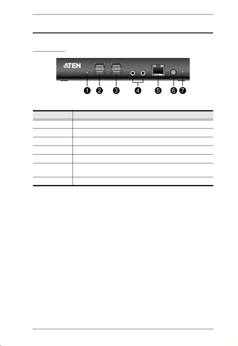
Front View
No. Component
1Reset Switch
2 USB Ports (Peripherals)
3 USB Ports (Keyboard and Mouse)
4 Audio Ports
5 Cascade Port
6 Power Push Button (Press to enter the standby mode; press again
to wake the unit)
7 Power LED (Power on: Blue; Standby: Orange)
Chapter 1. Introduction
3
KVM over IP Console Station User Manual
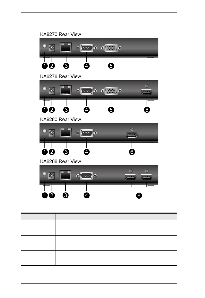
Rear View
No. Component
1 Grounding Terminal
2 Power Jack
3 LAN Port
4COM Port
5 VGA Port (KA8270 and KA8278 only)
6 HDMI Port(s) (KA8278, KA8280 and KA8288 only)
4

Chapter 2. Hardware Setup
1. Important safety information regarding the placement and
grounding of this device is provided on page 81 and
onwards. Please review it before proceeding.
2. Make sure that power to all the devices you will be
connecting up have been turned off. You must unplug the
power cords of any computers that have the Keyboard
Power On function.
Chapter 2
Hardware Setup
Overview
This chapter outlines different ways of mounting your KVM over IP
Console Station as well as a quick hardware connection summary in the
form of single stage installation.
Before You Begin
5

KVM over IP Console Station User Manual
Mounting
The KVM over IP Console Station can be rack mounted or wall
mounted. The following sections take you through the procedures for
each method.
Rack Mounting
The KVM over IP Console Station is designed to be mounted at the rear
of a rack, where it occupies 0U to save space.
1. Remove two bottom screws of the unit and use those to screw the
mounting bracket to the bottom of the unit as shown in the diagram
below:
2. Screw the mounting bracket to any convenient location on the rack.
Note: Rack screws are not provided to mount the unit. We
recommend that you use M5 x 12 Phillips type I cross screws.
6
Chapter 2. Hardware Setup
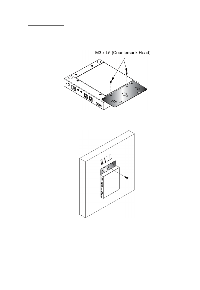
Wall Mounting
1. Remove two bottom screws of the unit and use those to screw the
mounting bracket to the bottom of the unit as shown in the diagram
below:
2. Use the mounting bracket’s center screw hole to mount the unit on
a wall.
7

KVM over IP Console Station User Manual
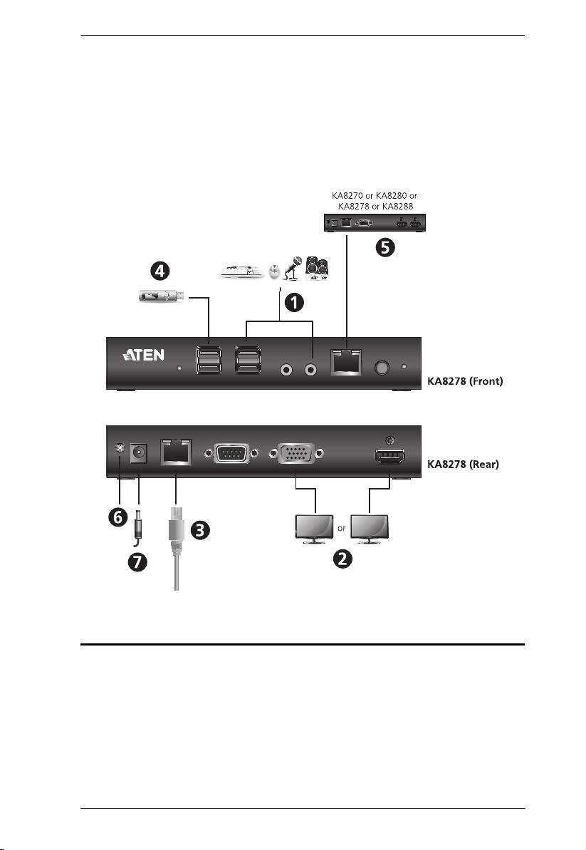
Single Stage Installation
For a single stage installation, refer to the installation diagram and
procedures shown below (KA8278 is used as an example):
Note: The numbers shown in the diagram are the installation steps
corresponding directly to the steps below.
1. Plug the connectors of your USB mouse, USB keyboard, microphone, and speakers into their respective ports on the front panel of
the KVM over IP Console Station. Each port is color coded and
marked with an icon.
2. Plug the monitor into the VGA or the HDMI port on the rear panel of
the KVM over IP Console Station.
Note:
1. KA8270 supports 1 VGA video output, KA8278 supports 1 VGA
and 1 HDMI video outputs, KA8280 supports 1 HDMI video
output, and KA8288 supports 2 HDMI video outputs.
2. For models that support two video outputs (KA8278 and
KA8288), the video interface at the inner side (e.g., the VGA
video interface of KA8278) is the Primary Display, the video
interface at the outer side is the Secondary Display.
3. Login page will appear on Primary Display and make sure you
use the Primary Display to log in.
3. Plug an Ethernet cable from the LAN into the KVM over IP Console
Station’s LAN port.
4. (Optional) Plug USB drives into the dedicated USB ports located on
the front panel.
5. (Optional) To cascade one more unit, plug one end of a Cat 5e
cable into the Cascade port on the front panel, and then plug the
other end of the cable to the LAN port of another KVM over IP
Console Station. The added unit will gain the first unit’s Internet
connection.
Configuration / control of each unit is separate.
Note: Do not connect the Cascade Port to a network switch or it will
cause a switching loop.
8
Chapter 2. Hardware Setup
6. (Optional) Use a grounding wire to connect the Grounding Terminal
on the rear panel of the KVM over IP Console Station to a suitable
grounded object.
7. Plug the power adapter into an AC source with the power cord; then
plug the other end into the KVM over IP Console Station’s Power
Jack.
Hot Plugging
KVM over IP console stations support hot plugging – components can
be removed and added back into the installation by unplugging and
replugging cables from the ports without the need to shut the unit down.
9

KVM over IP Console Station User Manual
Powering Off and Restarting
If it becomes necessary to power off the console station, please use the
shut down function (see Shutdown on page 62), disconnect the power
adapter and wait 30 seconds before reconnecting it back.
10
Chapter 3. Operation
Chapter 3
Operation
Overview
The KVM over IP console station can be used as a central control
station to monitor several KVM switches.
Available interfaces are described in the sections that follow.
Logging In
The KVM over IP Console Station can be used as a central control
station to monitor several KVM switches. A valid Username and
Password are required to login.
If you supply invalid login information, the authentication routine will
return an Invalid Username or Password, or Login Failed message. If
you see this type of message, log in again with a correct username and
password.
Note: If the number of invalid login attempts exceeds a specified
amount, a timeout period is invoked. You must wait until the timeout
period expires before you can attempt to log in again. See Login
Failures on page 48 for further details.
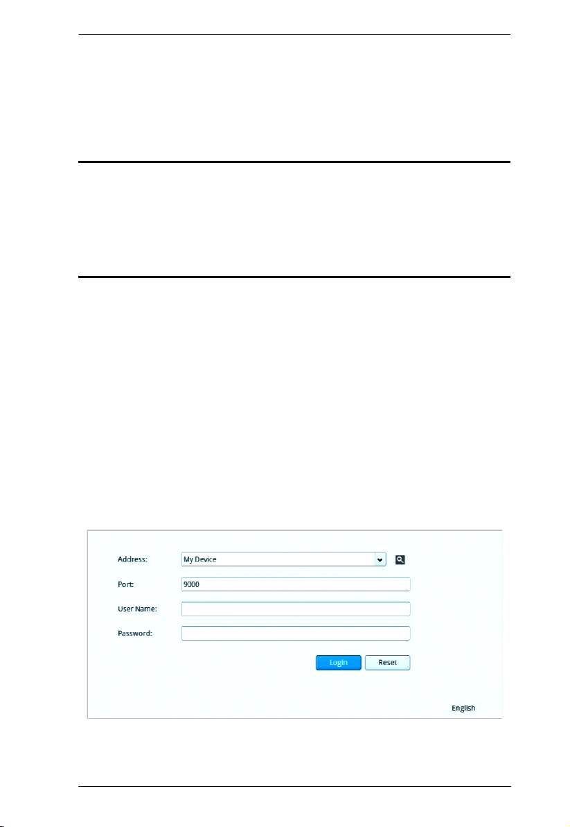
The login screen is shown below:
11

KVM over IP Console Station User Manual
The KVM over IP console station supports two modes:
a) KVM over IP console station mode: Logging into the console
station (My Device).
b) KVM device mode: Logging into a KVM device directly.
Follow the steps below to log in:
1. If you wish to log into a KVM device directly, specify the device’s IP
Address and its Port.
For the KVM over IP console station login, select “My Device” from
the drop down menu for the Address field and go to the next step.
Note:
1. As an alternative, you can drag your mouse over the magnifying
glass symbol to find the addresses of the devices on the same
local area network; or
2. Click the drop-down menu for a device list. The device list shows
the device login history. “My Device” is always shown at the top
of the list. The history can be cleared using a terminal command,
please see Terminal on page 59.
2. Enter a Username and Password (by default Username and
Password are administrator and password, respectively) and click
“Login” to log in.
Note: For security purposes, you should change the Username and
Password. (See Users and Groups on page 30)
3. (Optional) At the bottom right-hand corner, a language option is
available (English is shown as it is the default language). Click it to
select a preferred language for the interface.
After you successfully login, the dashboard of the console station will
appear. Please refer to Dashboard on page 13 for the operations.
12
Chapter 3. Operation
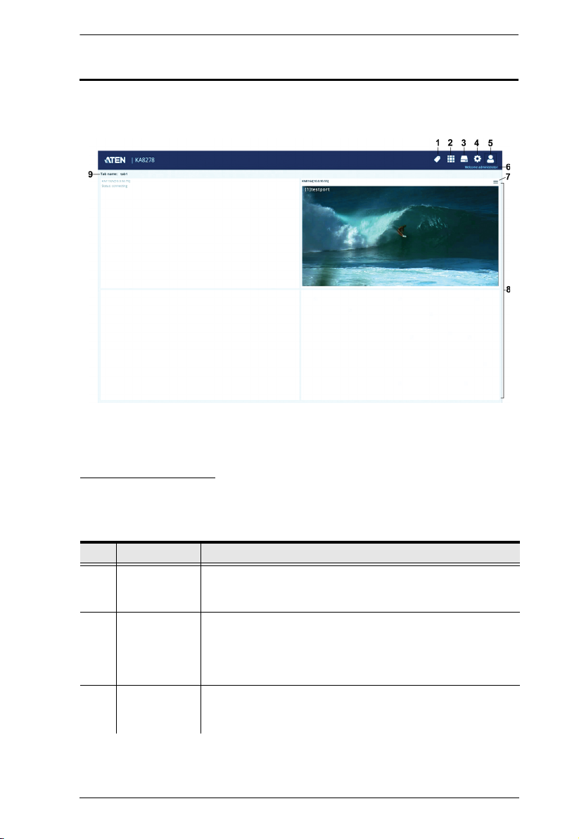
Dashboard
Once you have successfully logged in, the KVM over IP console
station’s user interface dashboard appears:
Note: The screen depicts an Administrator’s page. Depends on the
user’s type and permissions, not all of these elements will appear.
Page Components
The page components of the dashboard are described in the table
below:
No. Item Description
1 Tab
Management
2 Panel Array
Management
3Device
Management
Tab management allows users to separate KVM over IP
switches currently being monitored into different tab
groups or select which tab is to be displayed.
Panel array management allows users to
simultaneously display the ports connected to the KVM
over IP switches. The ports can also be grouped into
different groups and only simultaneously display the
ports in the chosen group.
Device management allows users with administrative
authority to add devices to or remove devices from the
console station.
13

KVM over IP Console Station User Manual
No. Item Description
4System
Configuration
System configuration allows users with administrative
authority to manage users or groups, display device
information, configure network, advanced network
management (ANMS) or security settings, or manage
firmware upgrade, system backup / restore, push / pull
configurations to or from other devices, access
terminal, or reset system to factory default settings.
5 User Settings User settings allow users to change password,
configure preferences, logout, restart the system, shut
down the system, or display quick information about the
console station.
6 Username This displays the username.
7 Individual
Monitor
Option
Individual monitor option allows users to select which
port is to be displayed on an assigned display, open the
GUI or disconnect from the KVM over IP switch.
If the switch is disconnected, you can also click
Reconnect to reconnect the switch to the console
station.
For example, if you have a primary and secondary
display (KA8278 or KA8288), you can choose to display
one of the ports on the primary display while another
port on the secondary display. See Primary / Secondary
Display on page 16.
8 Available
KVM over IP
Switch
Monitor
Available KVM over IP switch monitor displays the
available KVM over IP switch at a glance. Each monitor
will consecutively rotate through the device’s connected
ports.
9 Tab name This displays the tab name.
Clicking the tab name will bring out an option
“Reconnect All Devices”. Click the option for the
reconnect operation.
14
Chapter 3. Operation
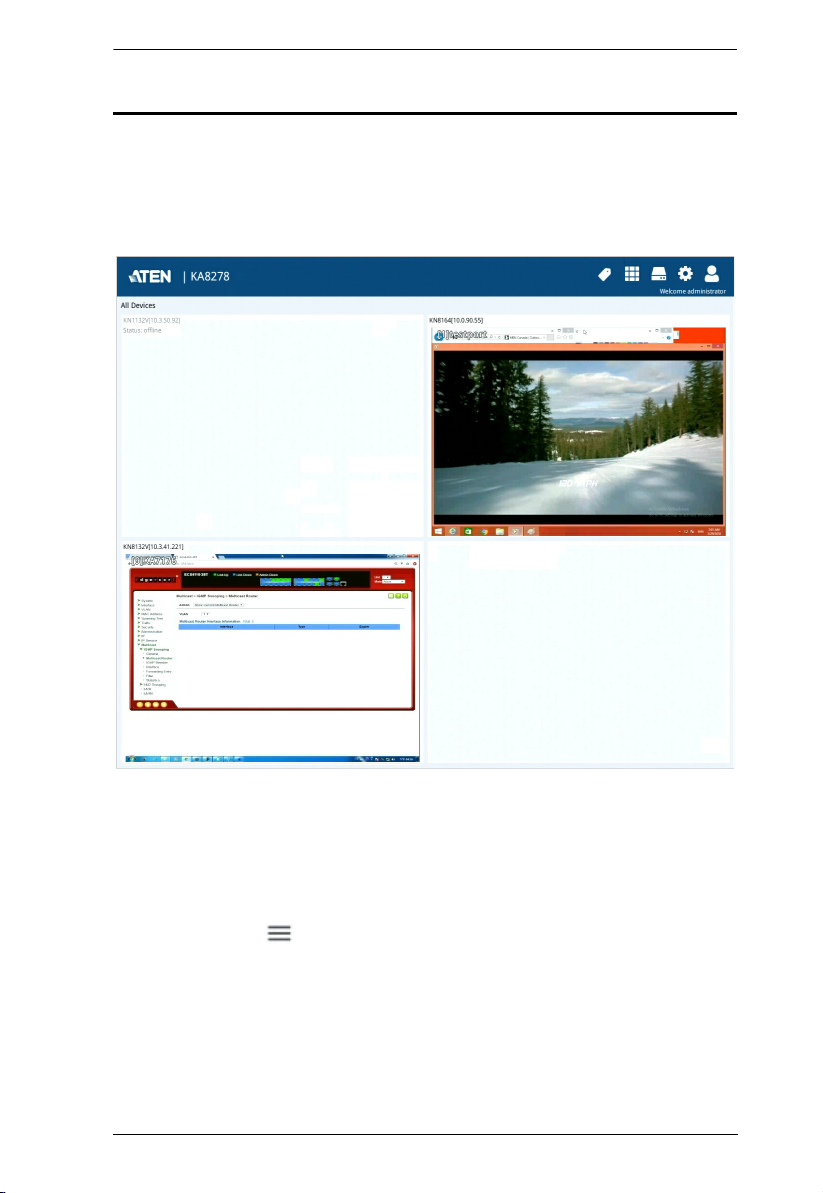
Dashboard Operation
The dashboard of the console station usually displays the connected
devices in an array of monitor units. Each of the unit corresponds to a
connected device. The unit will rotate consecutively between all the
connected ports.
Double-clicking a monitor will bring you to the port’s page.
For individual monitor options of a particular device, move your mouse
over its corresponding monitor unit. A menu icon will be shown on the
top right-hand corner of each unit.
= Menu icon
15
KVM over IP Console Station User Manual
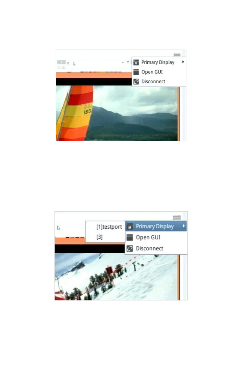
Monitor Unit Option
Clicking the Menu icon to display available options:
Primary / Secondary Display
Depends on your console station model (whether you have one or two
display ports), the menu may show a Primary Display option or both a
Primary Display option and a Secondary Display option. To display a
port on a primary or secondary display:
1. Mouse over the display (primary or secondary):
2. Click to select the port. The selected display should now show the
port’s screen. Your keyboard and mouse can now also control the
server connected to the port.
For the control of the server, the KVM over IP console station’s
16

Chapter 3. Operation
interface provides a toolbar to help you with the remote control
operations. Please refer to Toolbar Interface on page 63.
GUI
If you wish to use the KVM over IP switch’s GUI, click to select “Open
GUI”. Please refer to the KVM switch’s user manual for the GUI’s
operation.
Disconnect
Click “Disconnect” to disconnect from this KVM switch device.
Reconnect
Click “Reconnect” to reconnect to an offline KVM switch device.
17
KVM over IP Console Station User Manual
Tab / Panel Array Display and Management
Tab management allows users to separate KVM over IP switches
currently being monitored into different groups or select which tab group
is to be displayed on the dashboard.
Panel array management allows users to separate available ports into
different groups or select which panel array group is to be displayed on
the panel array page.
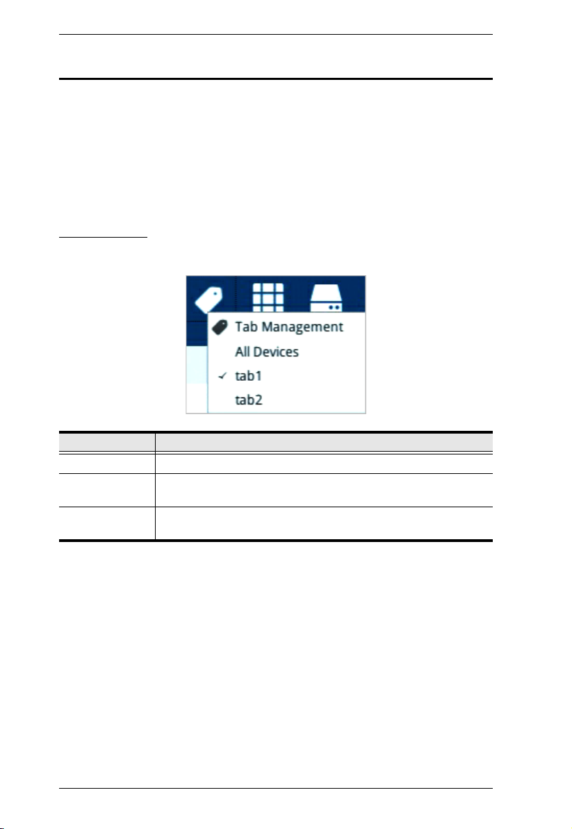
Tab Options
Click the Tab icon to display the tab options.
Option Description
Tab Management Click this option to allow you to add, delete or modify tabs (groups).
All Devices Click this option to display all the connected KVM over IP switches
Created tabs Select a created tab to display the KVM over IP switches in the tab
18
on the dashboard.
on the dashboard.
Chapter 3. Operation
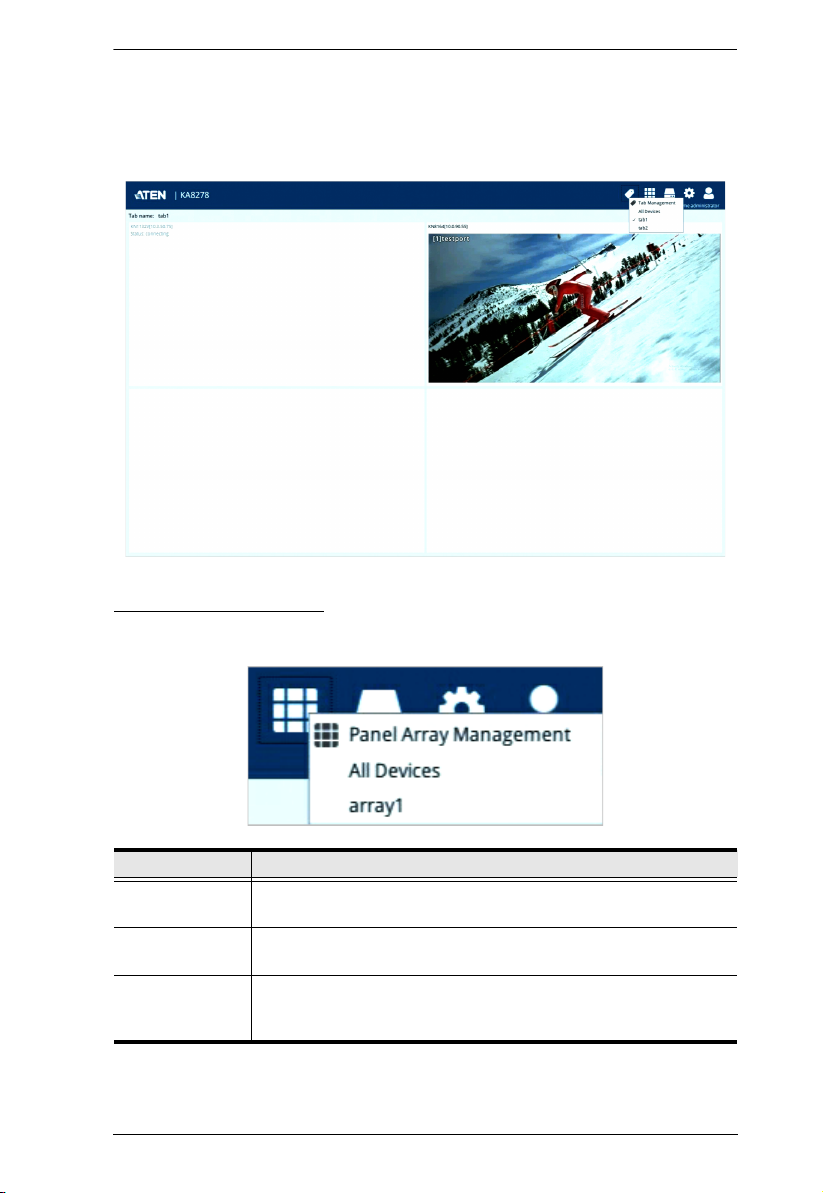
Tab Disp l ay
An example showing the KVM over IP switches in a tab displayed on the
dashboard (tab1 is the selected tab):
Panel Array Options
Click the Panel Array icon to display the panel array options:
Option Description
Panel Array
Management
All Devices All the ports connected KVM over IP switches are displayed on the
Created panel
arrays
This option allows you to add, delete or modify panel array
(groups).
panel array page.
Select a created panel array. All the ports connected to the KVM
over IP switches in the panel array are displayed on the panel array
page.
Note: Audio is not supported.
19
KVM over IP Console Station User Manual
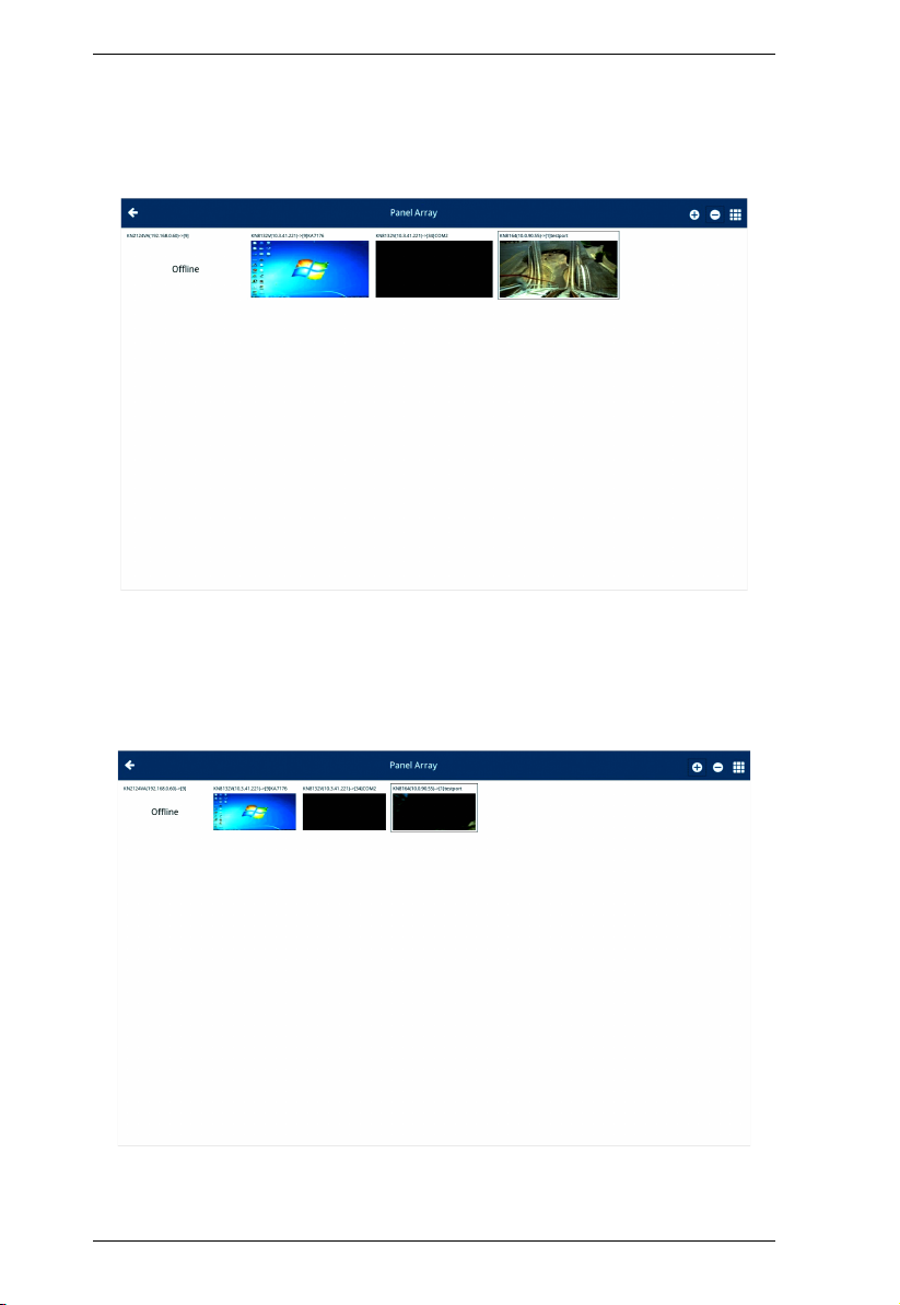
Panel Array Display
An example showing the ports of connected KVM over IP switches in a
panel array displayed (array1 selected):
Press the + icon to display more device ports (up to 64 ports) on a
smaller scale. Press the - icon to display less device ports on a larger
scale.
The diagram below displays a view on a smaller scale.
20
 Loading...