

Page 1

HDBaseT Installation Guide
Page 2
HDBaseT
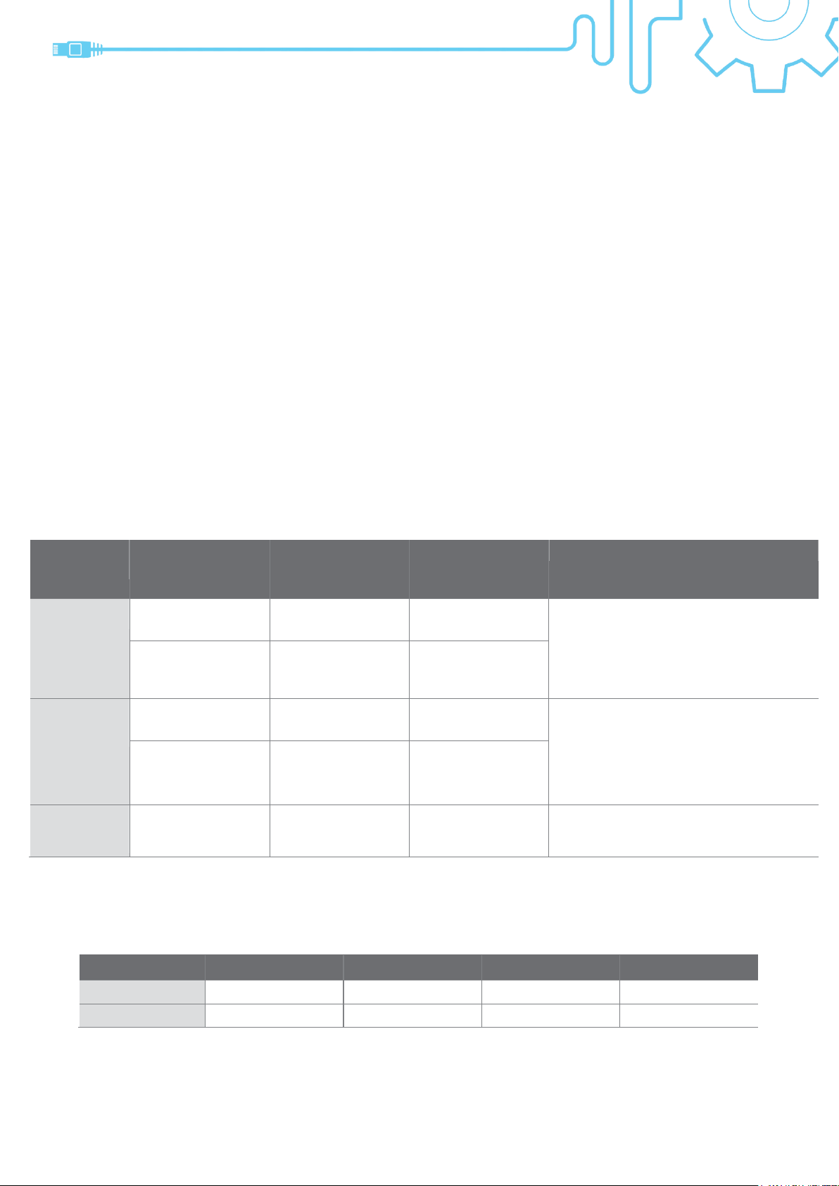
Type
Mode
Cat5e/6
Cat6a/7 &
ATEN 2L2910 Cat6
Model
HDBaseT 2.0
Standard
mode
4K2K@90m
1080P@100
4K2K@100m
1080P@100m
CE620* /CE624* /CE820 /CE920 and
future products
NOTE: For HDBaseT2.0, Cat6/6a/7
on the same segment.
Long Reach
mode
1080P@150m
1080P@150m
HDBaseT 1.0
Class A
Standard
mode
4K2K@70m
1080P@100
4K2K@100m
1080P@100m
VE811 /VE812 /VE1812 /VE814
/VE814A /VE813 /VE813A /CE610*
/CE610A* /VE2812T /VE2812EUT
/VE2812UST /VE816R and future
products
Long Reach
mode
1080P@150m
1080P@150m
HDBaseT 1.0
Class B (lite)
Standard
mode**
4K2K@35m
1080P@60m
4K2K@40m
1080P@70m
VE801/ VE802/ VE805R/ VE601*/
VE901 and future products
Type 30m
50m
70m
100m
CAT5e/6 6 4 2 1
CAT6a/7/2L-2910
6 6 6 6
ATEN HDBaseT Installation Guide
This document provides the best practices for installing Ethernet
cable with HDBaseT setups.
We strongly recommend to use ATEN HDBaseT certified cable (2L-2910) to provide
‧
best performance and to guarantee best quality.
The 2L-2910 has been verified to meet performance requirements set by the HDBaseT Alliance
and POH standard.
The 2L-2910 utilizes SF/UTP design with four unshielded 23 AWG twisted pair conductors.
Among the four unshielded twisted pair conductors, there is one cross filler to reduce cross talk.
The outer metal layer and the braid protect signal transmissions from electromagnetic
interference and reduce the impact caused by electrical noise.
With pure copper conductor and better cladding design, user does not need to worry the risk
of fire when use POH transmits huge current.
Thus, 2L-2910 is your best choice for HDBT solution.
Applying right cable type & length:
‧
*VE601 and CE610/CE610A/620/624 have a maximum resolution of 1920x1200 & 1600x1200.
** HDBaseT1.0 ClassB do NOT support Long Reach mode
The HDBaseT Alliance defines the maximum number of Ethernet cables in a bundle to be:
‧
Page 3
Magnetic
Field
Current through
the wire
ATEN HDBaseT Installation Guide
Crosstalk
‧
When installing in an
environment with lots of
structured cabling, do
your best to separate
out the Ethernet cable
from all other cables to
prevent crosstalk with
other signals.
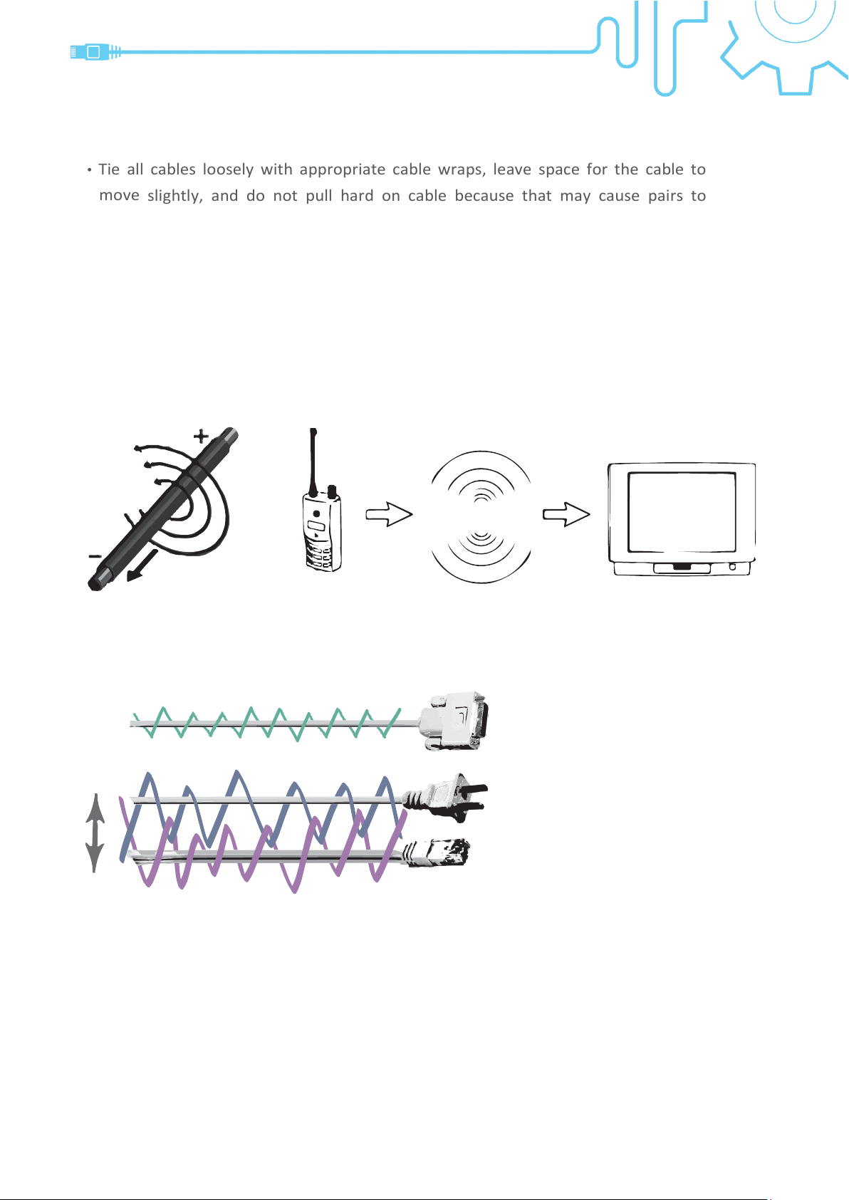
Tie all cables loosely with appropriate cable wraps, leave space for the cable to
‧
move
slightly, and do not pull hard on cable because that may cause pairs to
untwist and degrade performance. Always try to minimize damage to the cable
structure during installation and never drop or install anything on or over an
Ethernet cable.
Always keep cable away from equipment that may cause electromagnetic interference
‧
and
magnetic fields, such as high voltage electric cables, electric motors, Walkie-
Talkies, TVs and
elevators.
Electromagnetic
interference
Walkie-talkie TV set
Page 4
Video Source
100 meters
HDMI
cable
HDMI
cable
Wall-mounted
link segment
HDBaseT
Transmitter
Patch
Patch
HDBaseT
Receiver
RJ45
RJ45
ATEN HDBaseT Installation Guide
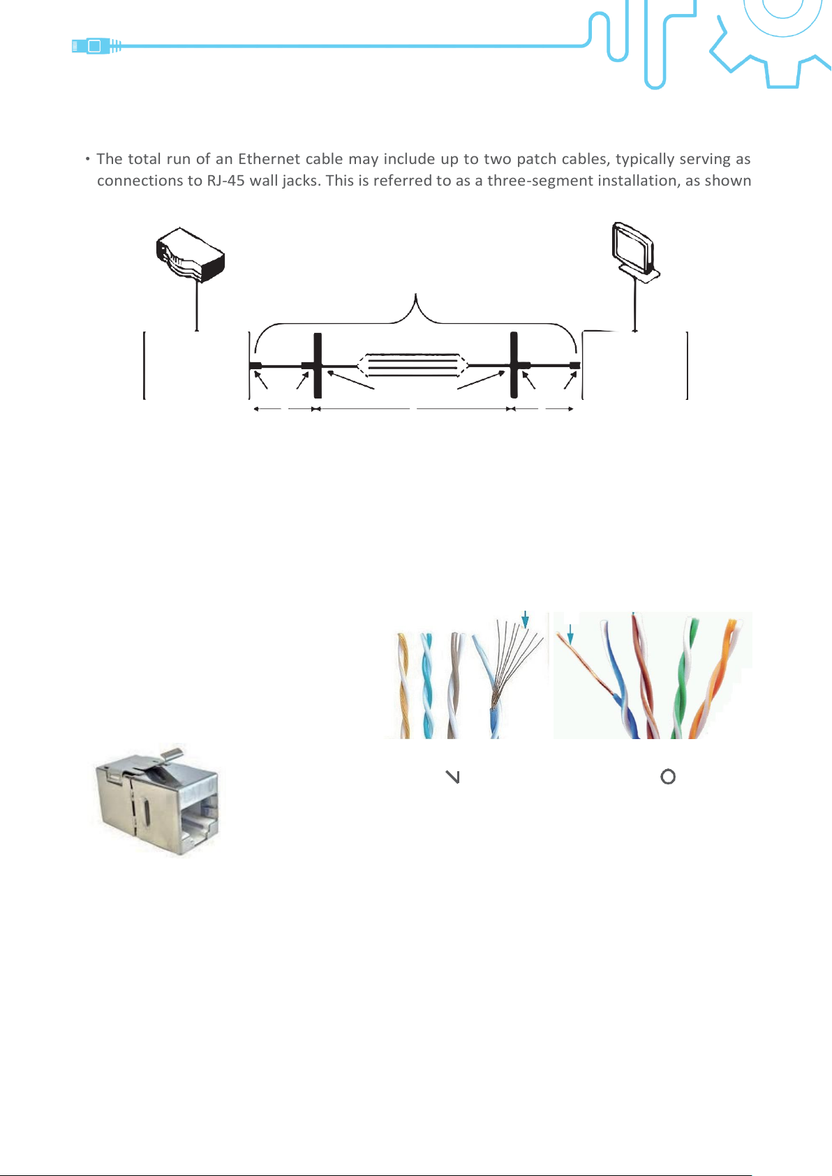
The total run of an Ethernet cable may include up to two patch cables, typically serving as
‧
connections to RJ-45 wall jacks. This is referred to as a three-segment installation, as shown
below:
Display
X Z Y
X = Left-side patch cable length ≤ 5 [meter] (as short as possible)
Y = Right-side patch cable length ≤ 5 [meter] (as short as possible)
Z = Wall segment ≤ 100 – X – Y [meter]
***Depends on different criteria, please refer HDBaseT type table of Page1
for the real number of distance.
Do not use patch cable for the wall
‧
segment. The wall segment requires
AWG 24/23 infrastructure cable.
Patch cable
( )
Shielded coupler
If pass-through points are required, use shielded couplers.
‧
Apply T568A or T568B standards for straight through cabling.
‧
solid wire
( )
Page 5
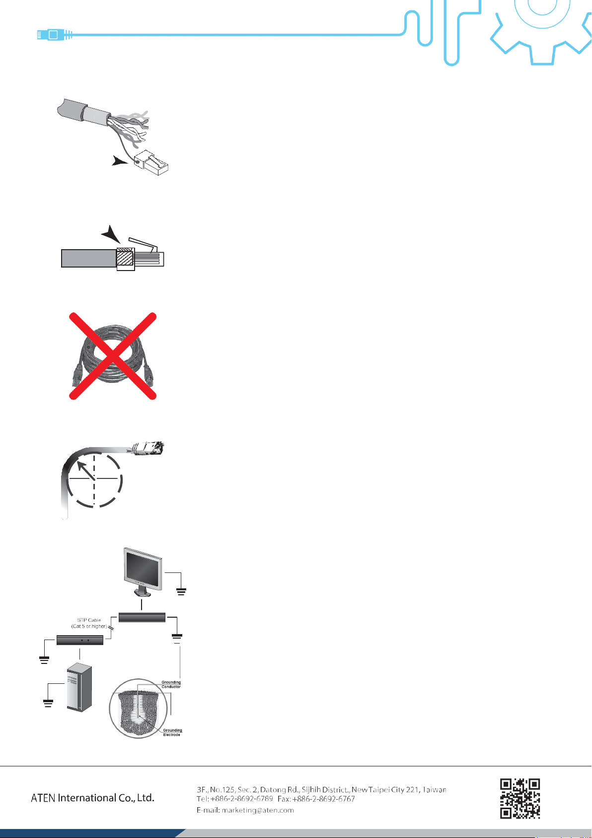
50mm
ATEN HDBaseT Installation Guide
‧
When using STP/FTP cable, make sure the drain wire is well
soldered to the metal casing of the RJ-45 connectors on both
ends.
Display
Source
Make sure the shielding makes tight contact with the top side in
‧
the RJ-45 connector.
Install cable of the shortest length possible between the HDBaseT
‧
Transmitter and Receiver while leaving a little wiggle room to
ensure the cable does not apply pressure to either device port.
Always avoid using unnecessary rolls of cable which will result in
performance degradation due to the increased length.
Do not bend the cable beyond a bend radius of 50 mm.
‧
Ground all devices.
‧
Ensure that every source and cable is grounded so that electrical
‧
interference does not have a path through your main signal.
Ensuring a proper ground will maintain your signal integrity for
the life of the installation.
08/2018 V3.0
 Loading...