


2/4/8-Port USB DVI/HDMI/DisplayPort
Single/Dual Display Secure KVM Switch
User Manual
www.aten.com
ATEN Secure KVM User Manual
EMC Information
FEDERAL COMMUNICATIONS COMMISSION INTERFERENCE STATEMENT: This equipment
has been tested and found to comply with the limits for a Class B digital service, pursuant to Part 15 of
the FCC rules. These limits are designed to provide reasonable protection against harmful interference
in a residential installation. Any changes or modifications made to this equipment may void the user’s
authority to operate this equipment. This equipment generates, uses, and can radiate radio frequency
energy. If not installed and used in accordance with the instructions, may cause harmful interference to
radio communications. However, there is no guarantee that interference will not occur in a particular
installation. If this equipment does cause harmful interference to radio or television reception, which
can be determined by turning the equipment off and on, the user is encouraged to try to correct the
interference by one or more of the following measures:
Reorient or relocate the receiving antenna.
Increase the separation between the equipment and receiver.
Connect the equipment into an outlet on a circuit different from that to which the receiver is
connected.
Consult the dealer or an experienced radio/TV technician for help.
FCC Caution: Any changes or modifications not expressly approved by the party responsible for
compliance could void the user's authority to operate this equipment.
This device complies with Part 15 of the FCC Rules. Operation is subject to the following two
conditions:
(1) this device may not cause harmful interference, and
(2) this device must accept any interference received, including interference that may cause
undesired operation.
KCC Statement
유선 제품용 / B 급 기기 ( 가정용 방송 통신 기기 ) 이 기기는 가정용 (B
급 ) 전자파적합기기로서 주로 가정에서 사용하는 것을 목적으로 하며 ,
모든 지역에서 사용할 수 있습니다
RoHS
This product is RoHS compliant.
ii
ATEN Secure KVM User Manual
SJ/T 11364-2006
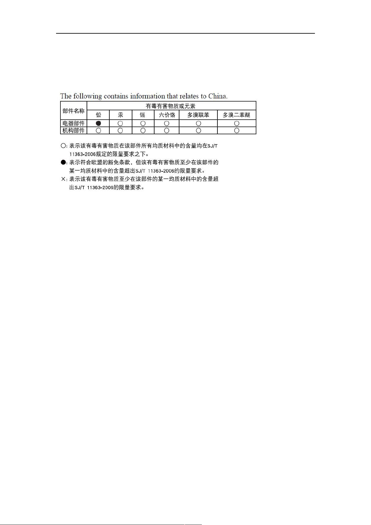
The following contains information that relates to China.
iii

ATEN Secure KVM User Manual
User Information
Online Registration
Be sure to register your product at our online support center:
https://eservice.aten.com/eServiceCx/Common/productRegister.do
Telephone Support
For telephone support, call this number:
International 886-2-8692-6959
China 86-10-5255-0110
Japan 81-3-5615-5811
Korea 82-2-467-6789
North America 1-888-999-ATEN ext 4988
United Kingdom 44-8-4481-58923
User Notice
All information, documentation, and specifications contained in this manual are subject to change
without prior notification by the manufacturer. The manufacturer makes no representations or
warranties, either expressed or implied, with respect to the contents hereof and specifically disclaims
any warranties as to merchantability or fitness for any particular purpose. Any of the manufacturer's
software described in this manual is sold or licensed as is. Should the programs prove defective
following their purchase, the buyer (and not the manufacturer, its distributor, or its dealer), assumes the
entire cost of all necessary servicing, repair and any incidental or consequential damages
resulting from any defect in the software.
The manufacturer of this system is not responsible for any radio and/or TV interference caused by
unauthorized modifications to this device. It is the responsibility of the user to correct such
interference.
The manufacturer is not responsible for any damage incurred in the operation of this system if the
correct operational voltage setting was not selected prior to operation. PLEASE VERIFY THAT THE
VOLTAGE SETTING IS CORRECT BEFORE USE.
iv

ATEN Secure KVM User Manual
Package Contents
The ATEN Secure KVM package consists of:
1 Secure KVM Switch
1 Power Cord
1 User Instructions*
Check to make sure that all of the components are present and in good order.
If anything is missing, or was damaged in shipping, contact your dealer.
Read this manual thoroughly and follow the installation and operation procedures carefully to
prevent any damage to the switch or to any other devices on the Secure KVM installation.
*Please visit our website to download the most up to date version of the manual.
© Copyright 2011–2017 ATEN® International Co., Ltd.
Manual Version: v1.05
Manual Date: 2020-03-06
ATEN and the ATEN logo are registered trademarks of ATEN International Co., Ltd. All rights
reserved.
All other brand names and trademarks are the registered property of their respective owners.
V

ATEN Secure KVM User Manual
Contents
EM
EMC
C Information
Information ................................
EMEM
C C
InformationInformation
SJ/T 11364
SJ/T 11364----2006
SJ/T 11364SJ/T 11364
User Information
User Information ................................
User InformationUser Information
Online Registration
Online Registration ................................
Online RegistrationOnline Registration
Telephone Support
Telephone Support ................................
Telephone SupportTelephone Support
User Notice
User Notice ................................
User NoticeUser Notice
Package Contents
Package Contents ................................
Package ContentsPackage Contents
About This Manual
About This Manual ................................
About This ManualAbout This Manual
Overview
Overview ................................
OverviewOverview
Conventions
Conventions ................................
ConventionsConventions
Product Information
Product Information ................................
Product InformationProduct Information
Chapter 1
Chapter 1
Chapter 1Chapter 1
Introduction
Introduction ................................
IntroductionIntroduction
................................................................
................................................................
Overview ........................................................................................................................... 1
................................................................
................................................................
2006 ................................
................................................................
20062006
................................................................
................................................................
................................................................
................................................................
................................................................
................................................................
................................................................
................................................................
................................................................
................................................................
................................................................
................................................................
................................................................
................................................................
................................................................
................................................................
................................................................
................................................................
................................................................
................................................................
................................................................
................................................................
................................................................
................................................................
................................................................
................................................................
................................................................
................................................................
................................................................
................................................................
................................................................
................................................................
................................................................
................................................................
................................................................
................................................................
................................................................
..............................................................
................................................................
................................................................
................................................................
................................................................
................................................................
................................................................
................................................................
...................................................
................................................................
..................................................
................................................................
...................................................
................................................................
...............................................
................................................................
...............................................
................................................................
..........................................................
................................................................
................................................
................................................................
..............................................
................................................................
.............................. ix
............................................................
..........................................................
................................................................
...............................................
................................................................
...........................................................
................................................................
................... ii
......................................
.................. iii
....................................
................... iv
......................................
............... iv
..............................
............... iv
..............................
.......................... iv
....................................................
................ VVVV
................................
.............. viii
............................
.......................... xxxx
....................................................
............... xxxx
..............................
........................... 1111
......................................................
viii
viiiviii
ii
iiii
iii
iiiiii
iv
iviv
iv
iviv
iv
iviv
iv
iviv
ix
ixix
Features ............................................................................................................................ 2
Requirements .................................................................................................................... 4
Console ............................................................................................................................. 4
Computers ........................................................................................................................ 4
Cables ............................................................................................................................... 4
Operating Systems ........................................................................................................... 5
Components ...................................................................................................................... 6
Front View ......................................................................................................................... 6
Rear View.......................................................................................................................... 7
Chapter 2
Chapter 2
Chapter 2Chapter 2
Hardware Setup
Hardware Setup ................................
Hardware SetupHardware Setup
Chapter 3
Chapter 3
Chapter 3Chapter 3
................................................................
................................................................
Before You Begin ............................................................................................................ 11
Stacking .......................................................................................................................... 13
Rack-Mount ..................................................................................................................... 13
Cable Connection ........................................................................................................... 13
Installation Diagram ........................................................................................................ 16
................................................................
................................................................
..................................................
................................................................
.................. 11
....................................
11
1111
Operation
Operation ................................
OperationOperation
................................................................
................................................................
Powering On ................................................................................................................... 17
Manual Switching ............................................................................................................ 18
Port ID Numbering .......................................................................................................... 18
LED Display .................................................................................................................... 18
Chassis Intrusion Detection ............................................................................................ 20
................................................................
................................................................
............................................................
................................................................
............................ 17
........................................................
17
1717
vi
ATEN Secure KVM User Manual
Smart Card and CAC Reader ......................................................................................... 20
Appendix
Appendix
AppendixAppendix
Safety Instructions .......................................................................................................... 21
General ........................................................................................................................... 21
Consignes de Sécurité .................................................................................................... 23
Général ........................................................................................................................... 23
Technical Support ........................................................................................................... 25
International .................................................................................................................... 25
North America ................................................................................................................. 25
Specifications .................................................................................................................. 26
Limited Warranty ............................................................................................................. 34
vii
ATEN Secure KVM User Manual
Console Video
Console Video Console Video
Console Video
ATTENTION
Tamper-evident seal
If the tamper-evident seal is missing or peeled, avoid using the product and contact
your ATEN dealer.
If all front panel LEDs flash continuously (except the Power LED), or the switch’s
enclosure appears breached, avoid using this product and contact your ATEN dealer.
This Secure KVM Switch is equipped with active always-on chassis intrusion
detection security. Any attempt to open the enclosure will permanently damage,
disable the switch, and void the warranty.
About This Manual
This user manual is intended for system administrators and end users.
This user manual is provided to help you get the most from your ATEN Secure KVM Switch system. It
covers all aspects of installation, configuration and operation. An overview of the information found in
the manual is provided below.
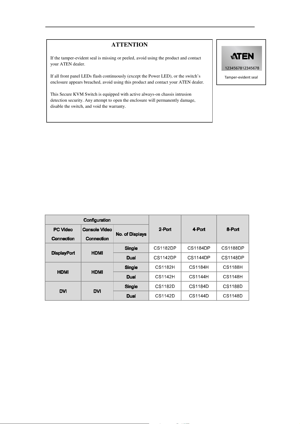
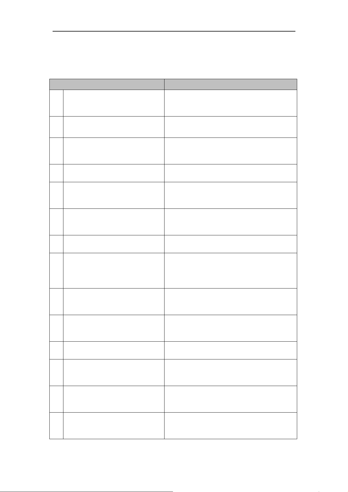
This user manual covers the following ATEN Secure KVM Switches:
Configuration
Configuration
ConfigurationConfiguration
2222----Port
PC Video
PC Video
PC Video PC Video
Connection
Connection
ConnectionConnection
DisplayPort
DisplayPort HDMI
DisplayPortDisplayPort
HDMI
HDMI HDMI
HDMIHDMI
DVI
DVI DVI
DVIDVI
Connection
Connection
ConnectionConnection
HDMI
HDMIHDMI
HDMI
HDMIHDMI
DVI
DVIDVI
No. of Displays
No. of Displays
No. of DisplaysNo. of Displays
Single
Single
SingleSingle
Dual
Dual
DualDual
Single
Single
SingleSingle
Dual
Dual
DualDual
Single
Single
SingleSingle
Dual
Dual
DualDual
Port 4444----Port
PortPort
CS1182DP
CS1142DP
CS1182H CS1184H CS1188H
CS1142H CS1144H CS1148H
CS1182D CS1184D CS1188D
CS1142D CS1144D CS1148D
Port 8888----Port
PortPort
CS1184DP CS1188DP
CS1144DP CS1148DP
Port
PortPort
viii

ATEN Secure KVM User Manual
Overview
Chapter 1, Introduction, introduces you to the ATEN Secure KVM Switch system. Its purpose,
features and benefits are presented, and its front and back panel components are described.
Chapter 2, Hardware Preparative Procedure, provides step-by-step instructions for setting up
your installation.
Chapter 3, Operation, explains the concepts involved in operating the ATEN Secure KVM Switch.
An Appendix, provides specifications and other technical information regarding the ATEN Secure
KVM Switch.
ix
ATEN Secure KVM User Manual
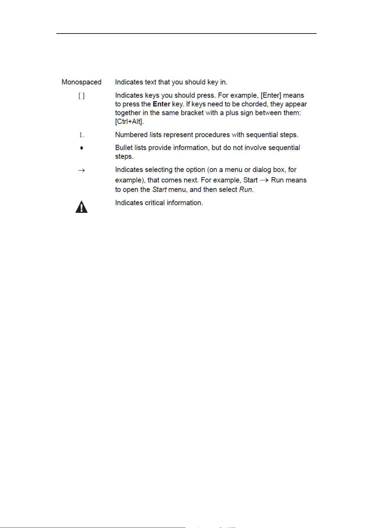
Conventions
This manual uses the following conventions:
Product Information
For information about all ATEN products and how they can help you connect without limits, visit
ATEN on the Web or contact an ATEN Authorized Reseller. Visit ATEN on the Web for a list of
locations and telephone numbers:
International http://www.aten.com
North America http://www.aten-usa.com
x

ATEN Secure KVM User Manual
This Page Intentionally Left Blank
XI

ATEN Secure KVM User Manual
Chapter 1
Introduction
Overview
The ATEN Secure KVM Switch series is NIAP-certified and compliant with NIAP PP 3.0 (Protection
Profile for Peripheral Sharing Switch version 3.0) requirements, satisfying the latest security requisites
set by the U.S. Department of Defense for peripheral sharing switches. Compliance ensures maximum
information security while sharing a single set of HIDs (keyboards, mouse, speakers, and CAC Reader)
between multiple computers. Conformity with Protection Profile v3.0 certifies that other USB
peripherals cannot be connected to the console ports of the Secure KVM Switch, and that only a
keyboard and mouse are accommodated, therefore providing high-level security, protection and
safekeeping of data.
The ATEN Secure KVM Switch hardware security includes tamper-evident tape, chassis intrusion
detection, and tamper-proof hardware, while software security includes restricted USB connectivity –
non-HIDs (Human Interface Devices) are ignored when switching – an isolated channel per port that
makes it impossible for data to be transferred between secure and unsecure computers, and automatic
clearing of the keyboard and mouse buffer when switching port focus.
By combining physical security with controlled USB connectivity and controlled unidirectional data
flow from devices to connected computers only, the ATEN Secure KVM Switch series gives you the
means to consolidate multiple workstations of various security classification levels with one keyboard,
monitor and mouse (KVM) console.
Note:
1. The National Information Assurance Partnership (NIAP) is a United States government initiative to
meet the security testing needs of IT consumers and manufacturers. It is operated by the National
Security Agency (NSA) and the National Institute of Standards and Technology (NIST).
2. The ATEN Secure KVM Switch series additionally satisfies Protection Profile version 3.0 for
Peripheral Sharing Switch (PSS).
1
ATEN Secure KVM User Manual
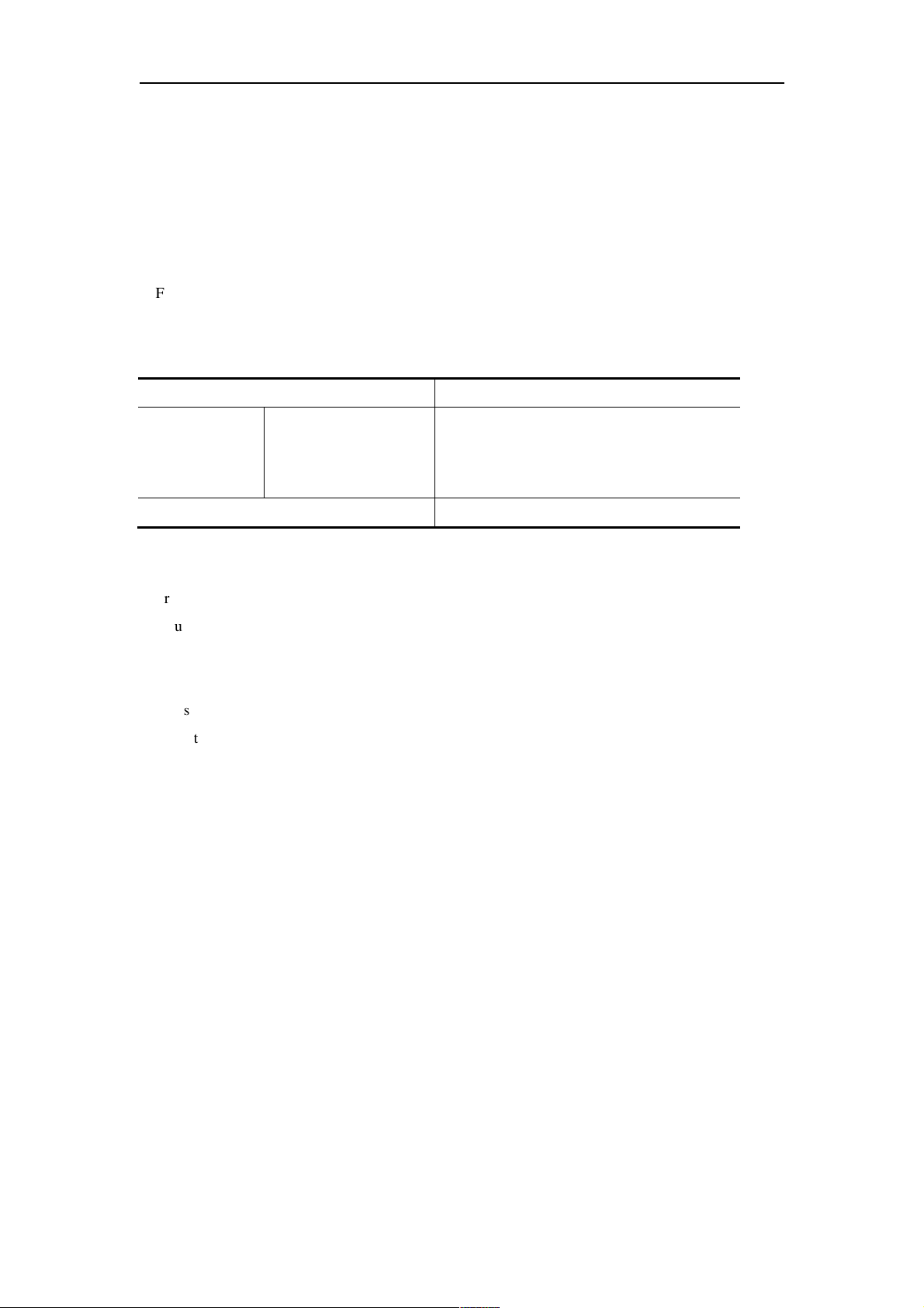
Features
FEATURES BENEFITS
2/4/8-Port USB DVI/HDMI/DisplayPort
■
Single/Dual Display Secure KVM Switch
Superior ultra high video resolution- up
■
to 4K UHD (3840 × 2160 @30Hz)*
Video DynaSync™ – exclusive ATEN
■
technology
DisplayPort AUX channel filtering
■
(DisplayPort Secure KVM only)
NIAP PP PSS v3.0 certified Provides the most advanced security features
■
Pushbutton port selection and secure
■
port switching
Channel Isolation Isolated channel per port — makes it impossible for
■
Shared peripherals and computer
■
isolation
Keyboard, Mouse, and Video EDID
■
emulation
Restricted USB connectivity Non-authorized HIDs (Human Interface Devices) or
■
Unidirectional data flow Secure design enables unidirectional data flow
■
Administrative configuration and event
■
log functions
Supports analogue audio (speaker
■
only)**
Active always-on chassis intrusion
■
detection
Reduces the costs involved in controlling up to 8
Single/Dual Display computers while offering data
isolation between shared peripherals and computers
Supports resolutions up to 3840 x 2160@30Hz* with
crystal clear image quality
ATEN Video DynaSyncTM eliminates boot-up display
problems and optimizes resolutions when switching
between ports
Non-qualified auxiliary channel traffic such as MCCS
and EDID write are rejected
required by the latest Protection Profile (PP) v3.0 for
Peripheral Sharing Switches (PSS)
Port selection via pushbutton only to enhance
security. Keyboard, Mouse, Video, Audio and CAC
reader switch together for secure switching.
data to be transferred between computers
Console USB and PS/2 keyboard/mouse are
supported. The always-on keyboard, mouse, and
display EDID emulation ensures isolation between
peripherals and connected computers.
Keyboard, mouse, and EDID emulation ensures
isolation between peripherals and connected
computers.
non-predefined CAC devices will be rejected /
ignored.
between devices and connected computers.
Secure access for authorized administrator to audit
KVM operation logs and secure configuration.
(Please refer to the Administrator’s guide.)
Only unidirectional speaker data is allowed
preventing the passage of the analogue audio by
microphone input or line input.
If the cover is removed from the switch, the unit
becomes inoperable and all front panel LEDs (except
the Power LED) flash continuously.
2

ATEN Secure KVM User Manual
Clears keyboard buffer when switching Keyboard data buffer is automatically purged when
■
switching KVM port focus.
Tamper-proof hardware All integrated circuits are soldered directly to the
■
circuit board to prevent tampering with the
components.
Tamper-evident tape Provides a visual indication of any attempt to gain
■
access to the switch’s internal components.
Firmware non-reprogrammable Prevents tampering and attempts to reprogram the
■
switch’s firmware.
Metal enclosure Rugged metal enclosure.
■
Note:
* HDMI and DisplayPort Secure KVM Switch series supports console video output resolutions up to 4K @ 30 Hz.
DVI Secure KVM Switches offer 3840 x 2160 @ 30 Hz video output on compatible HDMI-interfaced
monitors/computers with ATEN DVI-to-HDMI KVM cables.
**Only analogue speaker data input is supported. The ATEN Secure KVM Switch does not convert digital audio to
analogue audio.
3

ATEN Secure KVM User Manual
Requirements
Console
�
DVI (for DVI-interfaced Secure KVM) or HDMI (for HDMI and DisplayPort-interfaced Secure
KVM) monitor capable of the highest resolution that you will be using on any computer in the
installation
�
USB mouse
�
USB keyboard
�
PS/2 mouse (Optional)
�
PS/2 keyboard (Optional)
�
Speaker (Optional)
�
USB Smart card or CAC (Common Access Card) reader (Optional)
Computers
�
A DVI/HDMI/DisplayPort video output connector
�
A USB Type A port for keyboard and mouse
�
A USB Type A port for Smart Card or CAC reader (Optional)
�
A 3.5 mm jack Audio port for speaker (Optional)
Cables
The KVM cable sets which are specifically designed to work with this switch are not supplied in the
package and require a separate purchase.
For security, do not apply any cable that has a microphone audio input or line in audio input.
4

ATEN Secure KVM User Manual
Operating Systems
Suggested operating systems are shown in the table, below:
Note: Supports Linux Kernel 2.6 and higher.
5
ATEN Secure KVM User Manual
Components
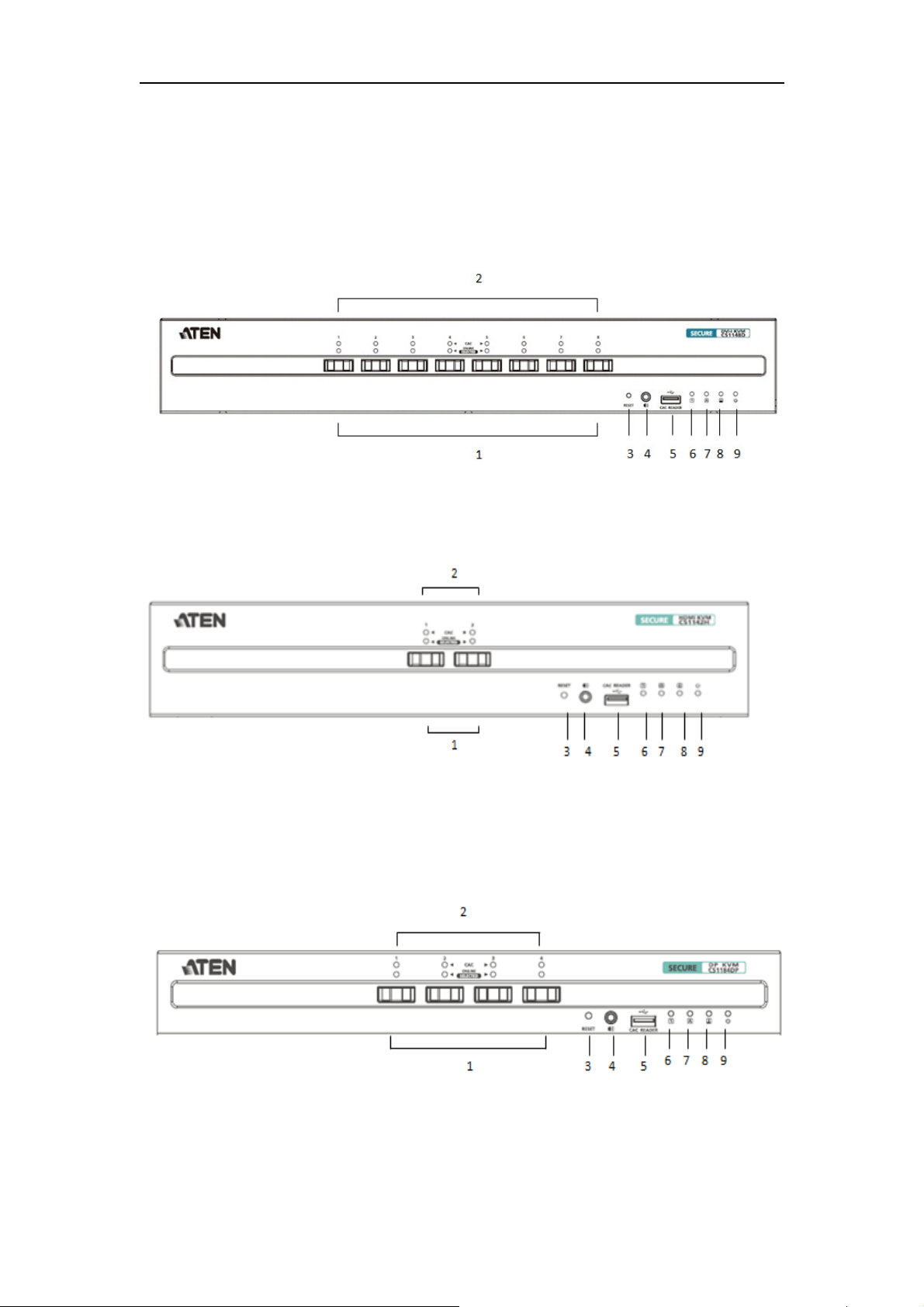
Front View
CS1188D
CS1142H
CS1184DP
6
ATEN Secure KVM User Manual
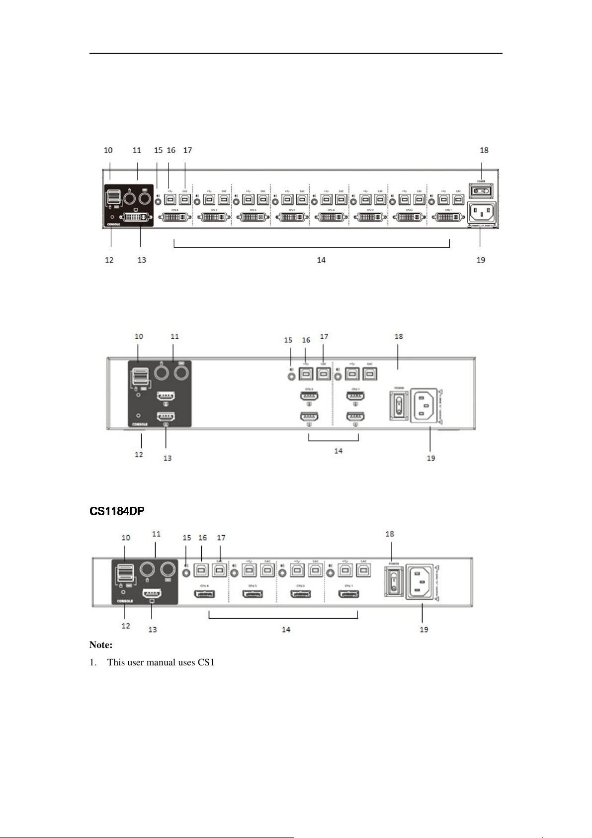
Rear View
CS1188D
CS1142H
CS1184D
CS1184DPPPP
CS1184DCS1184D
Note:
1. This user manual uses CS1188D, CS1142H, and CS1184DP to demonstrate each interface
(DVI/HDMI/DisplayPort), port number (2/4/8- Port), and number of displays (single/ dual)
included in ATEN Secure KVM
2. The console video of the CS1182DP/CS1184DP/CS1188DP/CS1142DP/CS1144DP/CS1148DP
(DisplayPort models) only supports an HDMI video output.
3. All the models support USB and PS/2 console keyboard/mouse and USB CAC card reader port.
7
ATEN Secure KVM User Manual
Lights dim orange to indicate that the computer attached to
CAC function of each port can be enabled or disabled by pressing
for more than 5
set
No.
No.
No.No.
1111
2222
3333
Component
Component Description
ComponentComponent
Port Selection
Pushbuttons
Port and CAC LEDs
Reset Button
Pressing a Port Selection Pushbutton brings together the keyboard,
mouse, video, audio, and CAC reader focus to the computer attached
to its corresponding port.
The Port / CAC LEDs are located on front panel to indicate Port/CAC
reader selection or connection status.
Port LEDs
Port LEDs (Lower row; Orange LEDs)
Port LEDsPort LEDs
� Online –
its corresponding port is connected and powered on.
� Selected – Lights bright orange to indicate that the computer
attached to its corresponding port has the KVM focus.
CAC LEDs
CAC LEDs (Upper
CAC LEDsCAC LEDs
� Online – Lights dim green to indicate that the computer attached to
its corresponding port has a USB CAC reader cable connection and
the CAC function is enabled.
� Selected – Lights bright green to indicate that the CAC function is
enabled and the computer attached to its corresponding port has the
CAC focus.
�None – No lights indicate the cable is not connected or CAC has
been disabled.
� Warning - Flashes to indicate that a non-qualified USB smart card /
CAC reader is connected when the corresponding port has the focus.
Note:
Note:
Note:Note:
1.
2. All front panel LEDs (except the Power LED) will flash
3. Port and CAC LEDs also indicate the status of the Secure KVM
Press this button to reset the ATEN Secure KVM Switch.
Note:
Note:
Note: Note:
When you perform a reset by pressing the reset button
seconds, the keyboard/mouse buffer will be purged and the switch will
reboot and perform a self-test. After a successful self-test, port focus
will be switched to port 1, and the CAC function of each port will be
to factory default setting (enabled).
If the Secure KVM fails to generate video on the monitor after a reset,
please power off the installation, check the cables, and follow the
(Lower row; Orange LEDs)
(Lower row; Orange LEDs)(Lower row; Orange LEDs)
(Upper row, Green LEDs)
row, Green LEDs)
(Upper(Upper
row, Green LEDs)row, Green LEDs)
the port selection pushbutton for more than 3 seconds (this is a
toggle feature). Please refer to the Operation section of this user
manual for more information.
continuously when a chassis intrusion or self-test failures (except
for Pushbutton jam) are detected. See Chassis Intrusion Detection
section for further details.
self-test status. See Operation section for further details
Description
DescriptionDescription
8
ATEN Secure KVM User Manual
e ports. The USB console
The console USB keyboard and mouse ports are interchangeable,
Switch. If supported, only basic (HID) keyboard/mouse operations
Num Lock, Caps Lock, and Scroll Lock LED on keyboards will
instructions found in this manual to power on the installation.
The cables from your speakers plug in here.
Note:
Note:
Only standard analogue speaker connections are allowed. The
4444
Audio Ports
USB Smart Card / CAC
5555
Reader Port
6666
Num Lock LED
7777
Caps Lock LED
8888
Scroll Lock LED
9999
Power LED
10
10
USB Console Ports
1010
Note: Note:
use of an analog microphone or line-in audio device is strictly
prohibited.
Only qualified USB authentication devices (e.g., standard smart card
and CAC reader) can be plugged into this port.
Note:
Note:
USB authentication device filter is configurable by authorized
Note: Note:
administrators for trusted devices (eg. USB token, USB Biometric
reader). Please refer to the Administrator’s Guide for details.
Lights green to indicate the Num Lock function has been turned on.
Note:
Note:
The Num Lock LED on the keyboard will be disabled due to
Note:Note:
security requirements.
Lights green to indicate the Caps Lock function has been turned on.
Note:
Note:
The Caps Lock LED on the keyboard will be disabled due to
Note:Note:
security requirements.
Lights green to indicate the Scroll Lock function has been turned on.
Note:
Note:
The Scroll Lock LED on the keyboard will be disabled due to
Note:Note:
security requirements.
Lights blue to indicate that the ATEN Secure KVM Switch is powered
on.
The USB keyboard and mouse plug into thes
keyboard port (lower port) and mouse port (upper port) are only
compatible with a standard USB keyboard/mouse.
Note:
Note:
Note:Note:
1.
meaning you can connect a keyboard to the mouse port and vice
versa. However, for optimal operation it is recommended that you
connect the USB keyboard to console's USB keyboard port and
the USB mouse to console's USB mouse port.
2. For security purposes, the ATEN Secure KVM Switch does not
support wireless keyboards. Do not attempt to connect a wireless
keyboard to the switch in any case.
3. Non-standard keyboards/mice with integrated USB hubs and/or
other USB-integrated devices may not be fully supported due to
the strict security standards and policy for the ATEN Secure KVM
will function.
4. Multimedia keys on the keyboard will not function due to the
security policy.
5. The
not function due to the security policy.
9
ATEN Secure KVM User Manual
console video connection has
11
11
PS/2 Console Ports
1111
12
12
Video LED(s)
1212
11113333
Console Monitor Port(s)
11114444
KVM Port Section
11115555
KVM Audio Port
11116666
KVM USB Port
USB Smart Card / CAC
11117777
(Common Access Card)
Reader Port
11118888
Power Switch
11119999
Power Socket The AC power cord plugs in here.
The PS/2 keyboard and mouse plug into these ports.
(PS/2 mouse port: Green; PS/2 keyboard port: Purple)
This LED lights green when the video connection is up and running.
The LED flashes when a non-qualified monitor is connected.
Note:
Note:
With the dual-display model, each
Note:Note:
a video LED.
The cable from your console monitor plugs in here.
Note
Note
: The dual-display model has two console monitor ports.
NoteNote
The custom KVM cables that attach to your computers plug in this
section.
The audio cable that attaches to your computer plugs in here.
Note
Note
: Only speaker connections are allowed. The use of an analog
NoteNote
microphone or line-in audio device is strictly prohibited.
The USB cable that attaches to your computer's keyboard / mouse
plugs in here.
The USB cable that attaches to your computer's USB Smart Card /
CAC reader plugs in here.
This is a standard rocker switch that powers the ATEN Secure KVM
Switch on and off.
10
ATEN Secure KVM User Manual
Tamper-evident seal
Chapter 2
Hardware Setup
Before You Begin
If any tamper-evident seal is missing or peeled, avoid using the
product and contact your ATEN dealer.
If all front panel LEDs except the Power LED flash continuously
or the switches’ enclosure appears breached, avoid using this
product and contact your ATEN dealer.
Tampering prevention and detection
1. The ATEN Secure KVM Switch includes tamper-evident tape to provide visual indications of
intrusion to the switches enclosure. If the tamper-evident seal is missing, peeled, or looks as if it’s
been adjusted, avoid using the product and contact your ATEN dealer.
2. The ATEN Secure KVM Switch is equipped with active always-on chassis intrusion detection. If a
mechanical intrusion is detected, the switch will be permanently disabled and all the front panel
LEDs (except the Power LED) will flash continuously. If the switches’ enclosure appears breeched
or all the LEDs are flashing continuously, stop using it, remove it from service immediately and
contact your ATEN dealer.
3. Any attempt to open the switches enclosure will activate the chassis intrusion detection security,
which will render it inoperable and void the warranty.
4. The ATEN Secure KVM Switch cannot be upgraded, serviced or repaired.
5. The ATEN Secure KVM Switch is equipped with active always-on chassis intrusion detection
security. Never attempt to open the enclosure. Any attempt to open the enclosure will permanently
damage and disable the switch.
6. The ATEN Secure KVM Switch contains an internal battery which is non-replaceable. Never
attempt to replace battery or open the switches’ enclosure.
Use always qualified and authorized peripheral devices
1. For security, the ATEN Secure KVM Switch supports only standard USB or PS/2 keyboard/mouse
(or pointing device). Do not connect a wireless keyboard/mouse, or any keyboard/mouse with an
internal USB hub or composite device function to the switch.
2. When connecting a non-qualified keyboard, the keyboard will not function. No keyboard
keystrokes will be seen on the screen.
3. When connecting a non-qualified mouse, the mouse will not function. No mouse cursor movement
will be seen on the screen.
11

ATEN Secure KVM User Manual
4. Num Lock LED, Caps Lock LED, and Scroll Lock LED on keyboard will be disabled due to the
security policy.
5. Special multimedia keys on the keyboard will be disabled due to the security policy.
6. For security, the ATEN Secure KVM Switch does not support an analogue microphone or line-in
audio input. Never connect a microphone to the switches’ audio output port, including a headset’s.
Standard analogue speakers and headsets are supported.
7. For security, the USB CAC port on the ATEN Secure KVM Switch by default only supports
authorized user authentication devices such as USB Smartcard or CAC readers. Do not connect
other USB devices to the USB CAC port. Non-qualified or non-authorized USB devices will be
rejected. For administrative configuration, please refer to the Administrator’s Guide and Port
Authentication Utility Guide for details.
8. For security, do not use any USB CAC authentication device or other peripherals that adopt an
external power source.
9. Always use a qualified monitor. Non-qualified monitors will be rejected.
10. Do not use wireless video transmitters or any docking device.
11. Do not connect any Thunderbolt device to the Secure KVM.
Secure Installation
1. Do not attempt to connect or install the following devices to the computers connected to the ATEN
Secure KVM Switch: TEMPEST computers; telecommunication equipment; frame grabber video
cards; or special audio processing cards.
2. Important safety information regarding the placement of this device is provided on page21. Please
review it before proceeding.
3. Before installation, make sure the power sources to all devices connected to the installation are
turned off. You must unplug the power cords of any computers that have the Keyboard Power On
function.
4. Hot-swapping of the console monitor is not allowed. Power off the Secure KVM Switch and the
monitor before changing the console monitor.
5. A computer connected to the Secure KVM Switch should only be powered on after all of the
connections to the device are made (video, USB and audio).
Secure Operation and Administration
Please refer to Administrator’s Guide for Secure KVM configuration and event log auditing
functions.
12
ATEN Secure KVM User Manual
Stacking
The ATEN Secure KVM Switch features a rugged, metal enclosure which provides stability and allows
the unit to be stacked on a desktop. The unit can be placed on any level surface that can safely support
its weight and the weight of the attached cables. Ensure that the surface is clean and free of materials
that can block the exhaust vents or otherwise interfere with normal operation of the KVM switch.
Rack-Mount
The ATEN Secure KVM Switch features a rack-mount design and offers rack-mount options.
Rack-mount kits which are specifically designed to work with this switch are not supplied in the
package and require a separate purchase.
Cable Connection
To set up your ATEN Secure KVM Switch installation, refer to the installation diagram on the
following page (the numbers in the diagrams correspond to the steps below), and do the following:
1. Plug your USB keyboard and USB mouse into the USB console ports located on the unit’s rear
panel. (The USB keyboard and mouse console ports are only compatible with standard USB
keyboard/mice. If you are using PS/2 keyboard/mouse, plug your PS/2 keyboard and PS/2 mouse
into the corresponding PS/2 ports.)
Note:
1. The console USB keyboard and mouse ports are interchangeable, meaning you can connect a
keyboard to the mouse port and vice versa. However, for optimal operation, it is recommended that
you connect the USB keyboard to console’s USB keyboard port and the USB mouse to console’s
USB mouse port.
2. For security purposes, the ATEN Secure KVM Switch does not support wireless keyboards. Do not
attempt to connect a wireless keyboard to the switch.
3. During KVM operation, non-standard keyboards with integrated USB hubs and/or other
USB-integrated devices may not be fully supported due to the strict security standards and policy for
the ATEN Secure KVM Switch. If supported, only basic (HID) keyboard operations will function.
4. When the Secure KVM Switch is powered on, if the keyboard or mouse is rejected, the keyboard and
mouse will be inoperable (mouse cursor freezes and/or no key strokes will respond on the computer)
2. Plug your console monitor(s) into the console video port(s) located on the unit’s rear panel and
power on the monitor.
Note:
1. When the ATEN Secure KVM Switch is powered on, the Video LED lights green when the video
connection is up and running. The Video LED flashes when a non-qualified monitor is connected.
2. Due to the security policy, the ATEN Secure KVM Switch does not support a monitor hot-swap. If
you would like to change the console monitor, you must first power off the entire installation.
3. Connected monitor will be filtered when the ATEN Secure KVM Switch is powered on.
Plug your speakers into the console's speaker jack located on the unit’s front panel.
Non-qualified monitor will be rejected (Video LED flashes). Please refer to the LED Display for
detailed visual identification.
13
ATEN Secure KVM User Manual
3. Plug your speakers into the console's speaker jack located on the unit’s front panel.
Note:
Only speaker connections are allowed. The use of an analogue microphone or line-in audio connection is
strictly prohibited.
4. With a single-display Secure KVM Switch, using a KVM cable set (not supplied with this package
and must be purchased separately), plug the video connector into any available video socket in the
KVM port section of the switch, then plug the accompanying USB (keyboard/mouse or CAC) and
speaker connectors into their corresponding USB and speaker ports.
With a dual-display Secure KVM Switch, using a KVM cable set (not supplied with this package and
must be purchased separately), plug the video connector for your primary monitor into any available
video socket A in the KVM port section of the switch, then plug the accompanying USB
(Keyboard/Mouse or CAC) and speaker connectors into their corresponding USB and speaker sockets.
Note:
1. Verify that all the plugs are in the same KVM port sockets (all in Port 1, all in Port 2, etc.). Each
socket is marked with an appropriate icon.
2. If the CAC reader function is to be disabled for certain PCs, it’s advised not to connect a USB CAC
cable in the installation.
5. At the other end of the KVM cable set, plug the USB, video, and speaker cables into their respective
ports on the computer.
With a dual-display Secure KVM Switch, use another video cable for your second monitor (not
supplied with this package and must be purchased separately), to plug the video connector into video
socket B on the same KVM port section of the switch. At the other end of the video cable, plug the
monitor cable in to its respective port on the computer.
Note:
1. Verify that the second video plug is in the same KVM port section as the first video plug (all in Port
1, all in Port 2, etc.). Each socket is marked with an appropriate icon.
2. Repeat steps 4, 5, 6, and 7 for each computer you are installing.
3. With a dual-display installation, for easier cabling at your site, you can also connect all the primary
video connectors to video sockets B, and secondary video connectors to video sockets A. Make sure
the console’s primary and secondary monitors are connected the same way.
14

ATEN Secure KVM User Manual
6. Plug the USB Smart Card / CAC reader to the CAC port on the front panel.
Note:
1. Only appropriate qualified USB authentication devices (e.g., Smart Card and CAC readers by default)
can be plugged into this port. During KVM operation, non-qualified or non-authorized USB devices
will be filtered and rejected (the CAC LED that has port focus will flash). Please refer to the LED
display for visual indications.
2. CDF (configurable device filtering) function can only be operated by authorized administrators.
.
Please refer to the Administrator’s Guide and Port Authentication Utility Guide for details.
7. Plug the female end of the power cord into the ATEN Secure KVM Switches' power socket; plug the
male end into an AC power source.
8. Turn on the ATEN Secure KVM Switch and check that the LEDs light up. The ATEN Secure KVM
Switch will start a self-test.
Note:
The ATEN Secure KVM Switch performs a security self-test at power-on and at each power cycle. Front
panel LEDs will indicate the self-test status and test result. Please refer to the Operation section and LED
Display section for visual identification details.
15

ATEN Secure KVM User Manual
Installation Diagram
13
16

ATEN Secure KVM User Manual
Chapter 3
Operation
Powering On
When you power on, reset, or power cycle the ATEN Secure KVM Switch, the switch will perform a
self-test to check the unit’s integrity and security functions.
During the self-test
�
All Port and CAC LEDs will turn ON and then OFF.
�
The KVM focus will be switched to port 1 when the self-test completes successfully (port 1 LED
lights bright orange).
Self-test failure
In the case of a self-test failure, the Secure KVM Switch becomes inoperable, with front panel LED
combinations indicating the potential cause of the failure (such as a button jam or KVM integrity
compromise)
�
A pre-defined combination of port and CAC LEDs indicate the cause of the failure.
�
If all front panel LEDs (except the Power LED) flash continuously, it means KVM tampering is
detected or a self-test failure has occurred (except for Pushbutton jam; see below)
�
If Pushbutton jam is detected, both the port’s LEDs will flash.
For security, the ATEN Secure KVM Switch becomes inoperable if a self-test fails. Please verify your
KVM installation, pushbuttons, and power cycle the Secure KVM Switch if this should happen. If the
self-test failure remains, stop using the ATEN Secure KVM Switch immediately, remove it from
service and contact your ATEN dealer.
After the ATEN Secure KVM Switch is powered on and ready, power on your computers. By default
the ATEN Secure KVM Switch will switch to port 1 after a successful self-test.
The ATEN Secure KVM Switch filters and emulates both a mouse and keyboard on each port after the
unit is powered on. If the keyboard, mouse, monitor, or Smart card / CAC reader fails to operate
properly, make sure that you are using the appropriate peripherals (qualified and authorized
peripherals); then power off the ATEN Secure KVM Switch, check all the cable connections, and
power on the unit again.
17

ATEN Secure KVM User Manual
Manual Switching
For increased security, the ATEN Secure KVM Switch offers manual port-switching only. This is
achieved by pressing the port selection pushbuttons located on the unit’s front panel.
Press and release a port selection pushbutton to bring the KVM focus to the computer attached to its
corresponding port (see Port ID Numbering, below). To meet maximum security and channel isolation
requirements, keyboard, mouse, video, audio, and USB CAC reader ports will be switched together.
The Selected Port LED lights orange to indicate that the computer attached to its corresponding port
has the KVM focus (keyboard, mouse, monitor, audio, and CAC reader).
The PC that has the port focus should be able to detect the peripherals after port switching.
If the PC fails to detect the keyboard, mouse, or CAC card reader:
- Verify that the keyboard, mouse, and/or CAC card reader is qualified.
- Verify if the keyboard, mouse, or CAC reader hasn’t failed.
- For USB CAC card reader (USB authentication device), please make sure the USB CAC cable has
been securely connected, and the CAC function is enabled.
- For USB CAC card reader port, please contact your administrator to verify if the device has been
authorized.
Port ID Numbering
Each KVM port on the ATEN Secure KVM Switch is assigned a port number (1–2 for the 2-Port
models; 1–4 for the 4-Port models; 1–8 for 8-Port models). The port numbers are marked on the rear of
the switch. See Rear View, page 7. The port ID of a computer is derived from the KVM port number it
is connected to.
LED Display
In addition to the Power LED, the ATEN Secure KVM Switch has Port LEDs (Online and Selected),
keyboard lock (Num Lock/Caps Lock/Scroll Lock) LEDs and CAC LEDs that are built into the front
panel to indicate port / keyboard / CAC reader operating status. A video LED is located on back panel
to indicate the operating status of the video connection. These LEDs also serve as the alarm notification
for KVM security issues.
18

ATEN Secure KVM User Manual
for
Port and CAC LEDs will flash constantly when a chassis intrusion is
LED
Power LED
Video LED
Port LED
CAC LED
LED Indication
LEDLED
The Power LED is on the front panel and lights blue to indicate that
the KVM switch is powered on.
The Video LED is located on the back panel next to each video
connector.
� The LED lights green when the video connection is up and
running.
� The LED flashes when a non-qualified monitor is connected.
The Port LEDs are located on the front panel to indicate the port
selection or connection status.
� Online – Lights dim orange to indicate that the computer attached
to its corresponding port connected and powered on.
� Selected – Lights bright orange to indicate that the computer
attached to its corresponding port has the KVM focus.
Note:
Note:
Note: Note:
1. Port and CAC LEDs will flash constantly when a chassis
intrusion is detected. See Chassis Intrusion Detection section
details.
2. Port and CAC LEDs also indicate the status of the Secure KVM
self-test status. See Operation section for further details.
The CAC LEDs are located on front panel to indicate CAC reader
selection or connection status.
Online – Lights dim green to indicate that the computer attached to
its corresponding port has a USB CAC reader cable connection and
the CAC function is enabled.
Selected – Lights bright green to indicate that the CAC function is
enabled and the computer attached to its corresponding port has the
CAC focus.
None – No lights indicate the cable is not connected or CAC has
been disabled.
Warning - Flashes to indicate that a non-qualified USB Smart card /
CAC reader is connected when the corresponding port has the focus.
Note:
Note:
Note: Note:
- CAC function of each port can be enabled or disabled by pressing
the port selection button for more than 3 seconds (this is a toggle).
Please refer to Operation section for details.
-
detected. See Chassis Intrusion Detection section for further details.
Indication
IndicationIndication
Num Lock LED Lights green to indicate the Num Lock is enabled
Caps Lock LED Lights green to indicate the Caps Lock is enabled
19

ATEN Secure KVM User Manual
Scroll Lock LED Lights green to indicate the Scroll Lock is enabled
Chassis Intrusion Detection
To help prevent malicious tampering with the ATEN Secure KVM Switch, the switch becomes
inoperable and all front panel LEDs (except the Power LED) flash constantly when a chassis intrusion
(such as the cover being removed) is detected.
The intrusion detection feature is an always-on function. If all your front panel LEDs (except the Power
LED) flash continuously or the switch’s enclosure appears breached, avoid using this product and
contact your ATEN dealer.
Smart Card and CAC Reader
The USB Smart Card / CAC reader function of each port can be enabled or disabled (enabled by
default). Press the port selection pushbutton for more than 3 seconds then release it, to enable/disable
the CAC reader function for that port (this is a toggle feature). The CAC LEDs are used to indicate the
CAC reader operation status.
If the CAC reader function is to be disabled for certain PCs, it’s advised not to connect a USB CAC
cable to the installation.
20

ATEN Secure KVM User Manual
Appendix
Safety Instructions
General
�
This product is for indoor use only.
�
Read all of these instructions. Save them for future reference.
�
Follow all warnings and instructions marked on the device.
�
Do not place the device on any unstable surface (cart, stand, table, etc.). If the device falls, serious
damage will result.
�
Do not use the device near water.
�
Do not place the device near, or over, radiators or heat registers.
�
The device cabinet is provided with slots and openings to allow for adequate ventilation*.To ensure
reliable operation, and to protect against overheating, the cabinet must never be blocked or covered.
�
The device should never be placed on a soft surface (bed, sofa, rug, etc.) as this will block its
ventilation openings*. Placing devices without slots or openings on a soft surface will affect the heat
dissipation.
�
The device should not be placed in a built in enclosure unless adequate ventilation has been
provided.
�
Never spill liquid of any kind on the device.
�
Unplug the device from the wall outlet before cleaning. Do not use liquid or aerosol cleaners. Use a
damp cloth for cleaning.
�
The device should be operated from the type of power source indicated on the marking label. If you
are not sure of the type of power available, consult your dealer or local power company.
�
The device is designed for IT power distribution systems with 230V phase-to-phase voltage.
�
To prevent damage to your installation it is important that all devices are properly grounded.
�
The device is equipped with a 3-wire grounding type plug. This is a safety feature. If you are unable
to insert the plug into the outlet, contact your electrician to replace your obsolete outlet. Do not attempt
to defeat the purpose of the grounding-type plug. Always follow your local/national wiring codes.
�
Do not allow anything to rest on the power cord or cables. Route the power cord and cables so that
they cannot be stepped on or tripped over.
�
If an extension cord is used with this device make sure that the total of the ampere ratings of all
products used on this cord does not exceed the extension cord ampere rating. Make sure that the total of
all products plugged into the wall outlet does not exceed 15 amperes.
�
To help protect your system from sudden, transient increases and decreases in electrical power, use a
surge suppressor, line conditioner, or uninterruptible power supply (UPS).
�
Position system cables and power cables carefully; Be sure that nothing rests on any cables.
�
Never push objects of any kind into or through cabinet slots. They may touch dangerous voltage
points or short out parts resulting in a risk of fire or electrical shock.
21

ATEN Secure KVM User Manual
�
Do not attempt to service the device yourself. Refer all servicing to qualified service personnel.
�
If the following conditions occur, unplug the device from the wall outlet and bring it to qualified
service personnel for repair.
�
The power cord or plug has become damaged or frayed.
�
Liquid has been spilled into the device.
�
The device has been exposed to rain or water.
�
The device has been dropped, or the cabinet has been damaged.
�
The device exhibits a distinct change in performance, indicating a need for service.
�
The device does not operate normally when the operating instructions are followed.
�
Suitable for installation in Information Technology Rooms in accordance with Article 645 of the
National Electrical Code and NFPA 75.
CAUTION: Never attempt to replace battery or open the switch’s enclosure.
*Note: Not all devices have slots or openings to allow for ventilation
22

ATEN Secure KVM User Manual
Consignes de Sécurité
Général
�
Ce produit est destiné exclusivement à une utilisation à l’intérieur.
�
Veuillez lire la totalité de ces instructions. Conservez-les afin de pouvoir vous y référer
ultérieurement.
�
Respectez l’ensemble des avertissements et instructions inscrits sur l’appareil.
�
Ne placez jamais l’unité sur une surface instable (chariot, pied, table, etc.). Si l’unité venait à tomber,
elle serait gravement endommagée.
�
N’utilisez pas l’unité à proximité de l’eau.
�
Ne placez pas l’unité à proximité de ou sur des radiateurs ou bouches de chaleur.
�
Le boîtier de l’unité est destiné à assurer une ventilation adequate*. Pour garantir un fonctionnement
fiable et protéger l’unité contre les surchauffes, le boîtier de l’unité ne doit jamais être obstrué ou
couvert.
�
L’unité ne doit jamais être placée sur une surface molle (lit, canapé, tapis, etc.) car ceci obstruerait
les ouvertures de ventilation*. Le fait de placer des appareils sans fente ni ouverture sur une surface
souple affecte la dissipation thermique.
�
L’appareil ne doit pas être placé dans une enceinte intégrée à moins de lui fournir une ventilation
adéquate.
�
Ne renversez jamais de liquides de quelque sorte que ce soit sur l’unité.
�
Débranchez l’appareil de la prise secteur avant nettoyage. Ne pas utiliser de nettoyant liquide ou en
aérosol. Utiliser une chiffon humidifié pour le nettoyage.
�
L’appareil doit être alimenté par le type de source indiqué sur l’étiquette. Si vous n’êtes pas sûr du
type d’alimentation disponible, consultez votre revendeur ou le fournisseur local d’électricité.
�
L’appareil est conçu pour les systèmes de distribution d’alimentation informatique avec une tension
phase à phase de 230V
�
Afin de ne pas endommager votre installation, vérifiez que tous les périphériques sont correctement
mis à la terre.
�
L’unité est équipée d’une fiche de terre à trois fils. Il s’agit d’une function de sécurité. Si vous ne
parvenez pas à insérer la fiche dans la prise murale, contactez votre électricien afin qu’il remplace cette
dernière qui doit être obsolète. Respectez toujours les codes de câblage en vigueur dans votre
région/pays.
�
Veuillez à ce que rien ne repose sur le cordon d’alimentation ou les câbles. Acheminez le cordon
d’alimentation et les câbles de sorte que personne ne puisse marcher ou trébucher dessus.
�
En cas d’utilisation d’une rallonge avec cette unité, assurez-vous que le total des ampérages de tous
les produits utilisés sur cette rallonge ne dépasse pas l’ampérage nominal de cette dernière.
Assurez-vous que le total des ampérages de tous les produits branchés sur la prise murale ne dépasse
23

ATEN Secure KVM User Manual
pas 15 Ampères.
�
Pour contribuer à protéger votre système contre les augmentations et diminutions soudaines et
transitoires de puissance électrique, utilisez un parasurtenseur, un filtre de ligne ou un système
d’alimentation sans coupure (UPS).
�
Placez les câbles du système et les câbles d’alimentation avec précaution ; veillez à ce que rien ne
repose sur aucun des câbles.
�
N’insérez jamais d’objets de quelque sorte que ce soit dans ou à travers les fentes du boîtier. Ils
pourraient entrer en contact avec des points de tension dangereuse ou court-circuiter des pièces,
entraînant ainsi un risqué d’incendie ou de choc électrique.
�
N’essayez pas de réparer l’unité vous-même. Confiez toute opération de réparation à du personnel
qualifié.
�
Si les conditions suivantes se produisent, débranchez l’unité de la prise murale et amenez-la à un
technicien qualifié pour la faire réparer:
�
Le cordon d’alimentation ou la fiche ont été endommagés ou éraillés.
�
Du liquide a été renversé dans l’unité.
�
L’unité a été exposée à la pluie ou à l’eau.
�
L’unité est tombée ou le boîtier a été endommagé.
�
Les performances de l’unité sont visiblement altérées, ce qui indique la nécessité d’une réparation.
�
L’unité ne fonctionne pas normalement bien que les instructions d’utilisation soient respectées.
�
Peut être installé dans des salles de matériel de traitement de l’information conformément à l’article
645 du National Electrical Code et à la NFPA 75.
ATTENTION : Ne jamais tenter de remplacer la batterie interne ni d'ouvrir le boîtier du commutateur.
*Remarque : Tous les appareils ne disposent pas de fentes ou d’ouvertures qui permettent la
ventilation.
24
ATEN Secure KVM User Manual
Technical Support
International
�
For online technical support – including troubleshooting and
documentation: http://eservice.aten.com
�
For telephone support, See Telephone Support, page iv:
North America
Email Support support@aten-usa.com
Online
Technical
Support
Troubleshooting
Documentation
Software Updates
http://www.aten-usa.com/support
Telephone Support 1-888-999-ATEN ext 4988
When you contact us, please have the following information ready beforehand:
�
Product model number, serial number, and date of purchase.
�
Your computer configuration, including operating system, revision level,
expansion cards, and software.
�
Any error messages displayed at the time the error occurred.
�
The sequence of operations that led up to the error.
�
Any other information you feel may be of help.
25
ATEN Secure KVM User Manual
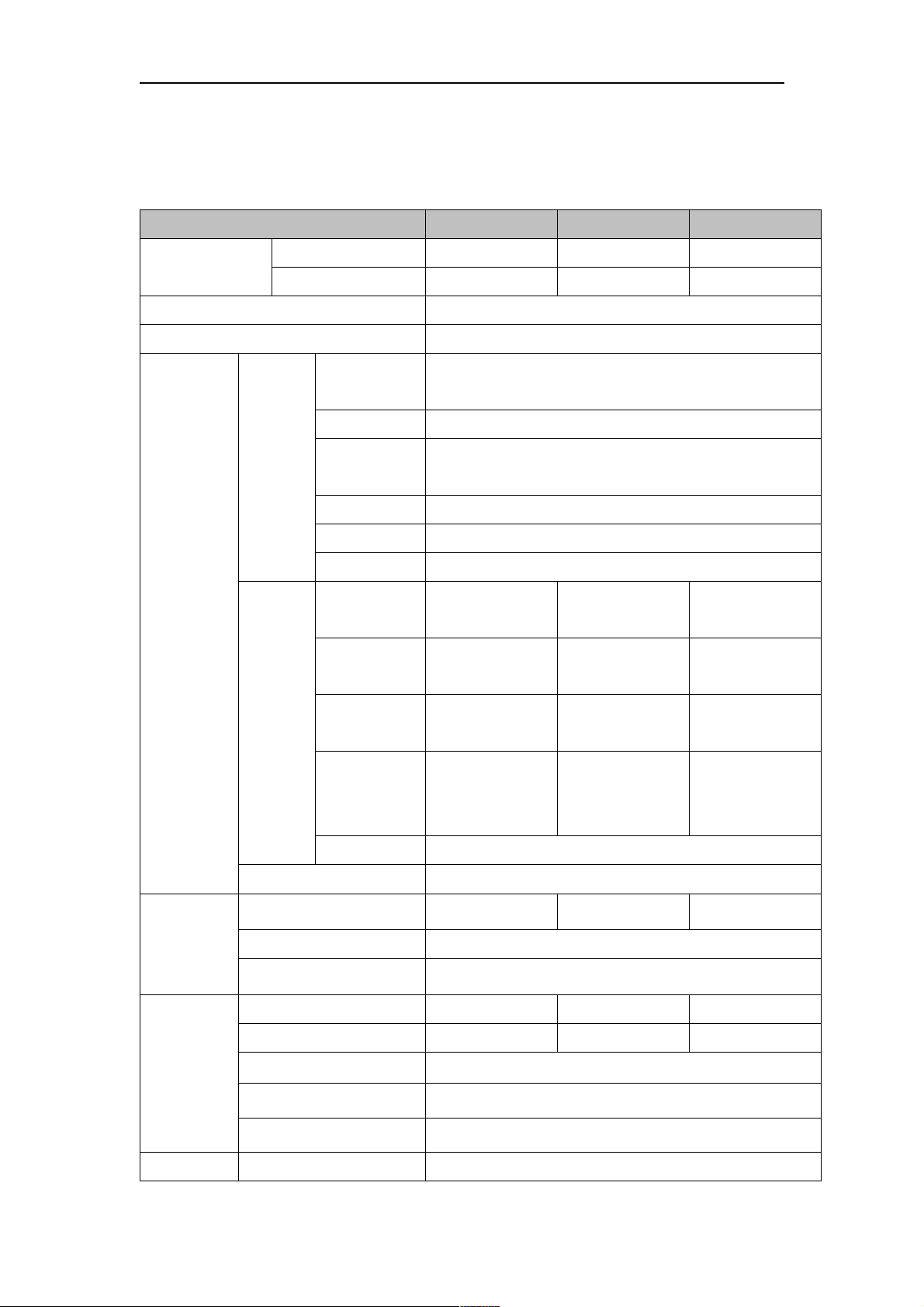
Specifications
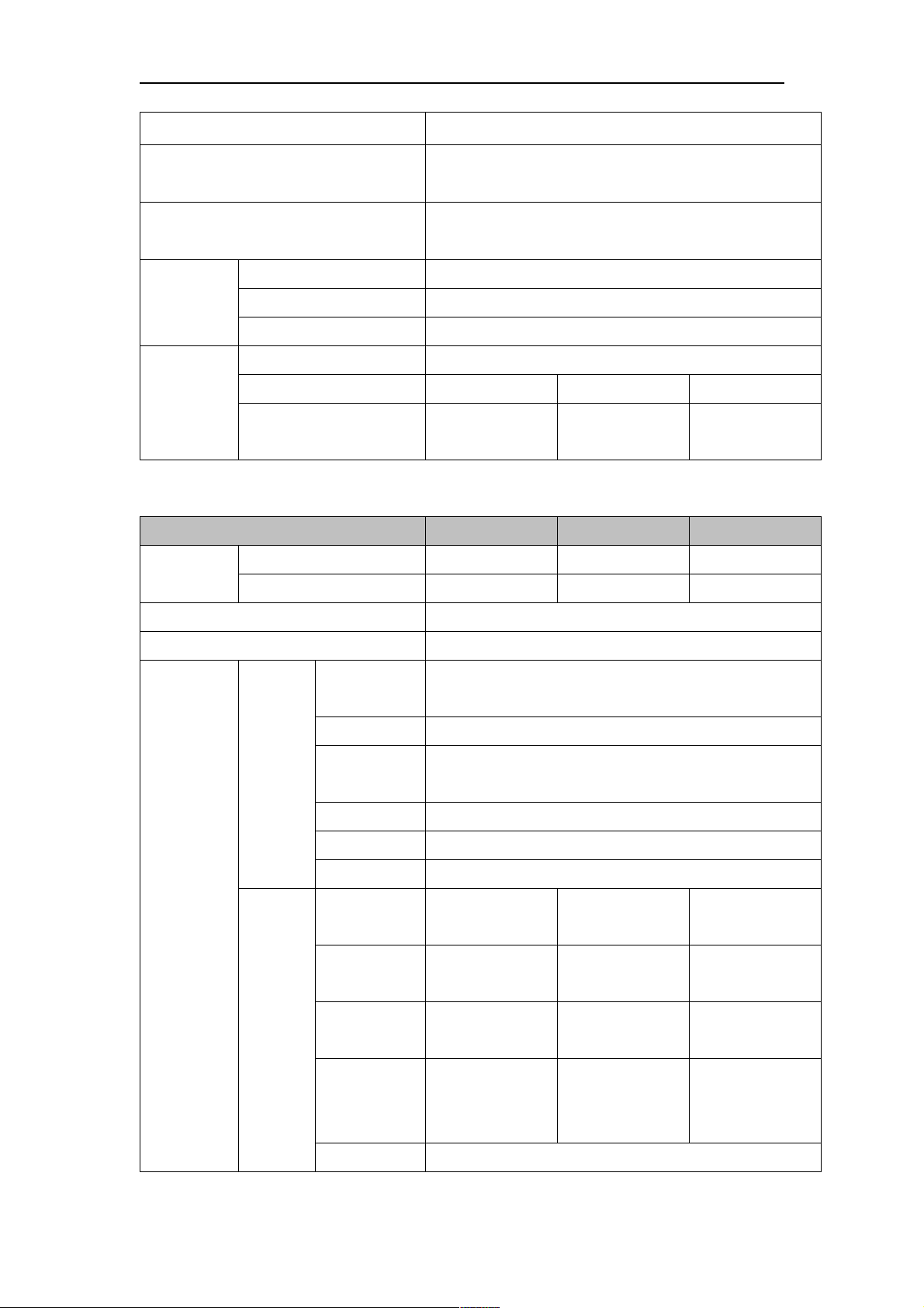
ATEN DisplayPort Single Display Secure KVM
Function CS1182DP CS1184DP CS1188DP
Computer
Connections
Console Connections 1 Direct
Port Selection Pushbutton
Connectors
Direct 2 4 8
Max. 2 4 8
Keyboard
Video 1 x HDMI 1.4 Female (Black)
Console
Mouse
Ports
Speaker 1 x Mini Stereo Jack Female (Green)
Microphone N/A
CAC 1 x USB Type A Female (Black)
Keyboard/
Mouse
Video
1 x 6-pin Mini-DIN Female (Purple)
1 x USB Type A Female (2/4-Port Black; 8-Port White)
1 x 6-pin Mini-DIN Female (Green)
1 x USB Type A Female (2/4-Port Black; 8-Port White)
2 x USB Type-B
Female (White)
2x DisplayPort 1.2
Female (Black)
4 x USB Type-B
Female (White)
4x DisplayPort 1.2
Female (Black)
8 x USB Type-B
Female (White)
8x DisplayPort 1.2
Female (Black)
Switches
LEDs
KVM
CAC
Ports
Speaker
Microphone N/A
Power 1 x 3-prong AC Socket
Port 2 x Pushbuttons 4 x Pushbuttons 8 x Pushbuttons
Reset 1 x Semi-recessed Pushbutton
Power 1 x Rocker
On Line / Selected 2 (Orange) 4 (Orange) 8 (Orange)
CAC activated 2 (Green) 4 (Green) 8 (Green)
Power 1 (Blue)
Key Lock LED 3 (Green; Num Lock, Caps Lock, Scroll Lock)
Console Video 1 (Green, on back panel)
2 x USB Type-B
Female (White)
2 x Mini Stereo
Jack Female
(Green)
4 x USB Type-B
Female (White)
4 x Mini Stereo
Jack Female
(Green)
8 x USB Type-B
Female (White)
8 x Mini Stereo
Jack Female
(Green)
Emulation Keyboard/Mouse USB
26
ATEN Secure KVM User Manual
Video Max. 3840 x 2160 @ 30 Hz (UHD)
Scan Interval N/A
I/P Rating 100–240V~ ; 50-60 Hz; 1A
Operating Temp. 0–50°C
Environment
Storage Temp. -20–60°C
Humidity 0–80% RH, Non-condensing
Housing Metal
Physical
Properties
Weight 1.78kg 1.79kg 3.05kg
Dimensions
(L x W x H)
335 x 164 x 44
mm
335 x 164 x 44
mm
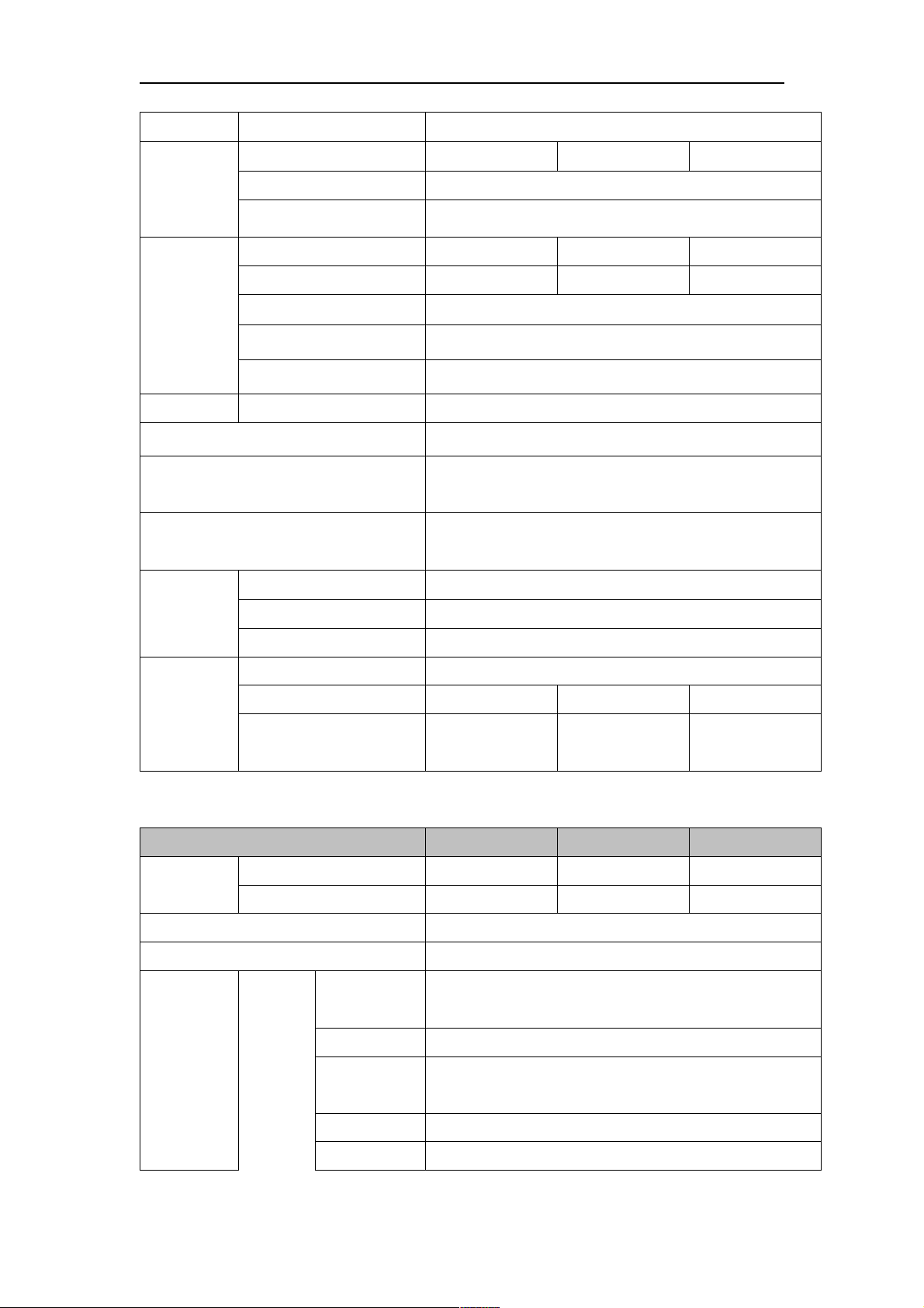
ATEN DisplayPort Dual Display Secure KVM
Function CS1142DP CS1144DP CS1148DP
Computer
Connections
Direct 2 4 8
Max. 2 4 8
Console Connections 1 Direct
Port Selection Pushbutton
1 x 6-pin Mini-DIN Female (Purple)
Keyboard
1 x USB Type A Female (2/4-Port Black; 8-Port White)
Video 2 x HDMI 1.4 Female (Black)
432 x 205 x 66
mm
Connectors
Console
Ports
KVM
Ports
Mouse
1 x 6-pin Mini-DIN Female (Green)
1 x USB Type A Female (2/4-Port Black; 8-Port White)
Speaker 1 x Mini Stereo Jack Female (Green)
Microphone N/A
CAC 1 x USB Type A Female (Black)
Keyboard/
Mouse
2 x USB Type-B
Female (White)
4x DisplayPort 1.2
4 x USB Type-B
Female (White)
8x DisplayPort 1.2
8 x USB Type-B
Female (White)
16xDisplayPort
Video
Female (Black)
2 x USB Type-B
Female (Black)
4 x USB Type-B
1.2 Female (Black)
8 x USB Type-B
CAC
Speaker
Female (White)
2 x Mini Stereo
Jack Female
(Green)
Female (White)
4 x Mini Stereo
Jack Female
(Green)
Female (White)
8 x Mini Stereo
Jack Female
(Green)
Microphone N/A
27
ATEN Secure KVM User Manual
Power 1 x 3-prong AC Socket
Port 2 x Pushbuttons 4 x Pushbuttons 8 x Pushbuttons
Switches
Reset 1 x Semi-recessed Pushbutton
Power 1 x Rocker
On Line / Selected 2 (Orange) 4 (Orange) 8 (Orange)
CAC activated 2 (Green) 4 (Green) 8 (Green)
LEDs
Power 1 (Blue)
Key Lock LED 3 (Green; Num Lock, Caps Lock, Scroll Lock)
Console Video 2 (Green, on back panel)
Emulation Keyboard/Mouse USB
Video Max. 3840 x 2160 @ 30 Hz (UHD)
Scan Interval N/A
I/P Rating 100–240V~ ; 50-60 Hz; 1A
Operating Temp. 0–50°C
Environment
Storage Temp. -20–60°C
Humidity 0–80% RH, Non-condensing
Housing Metal
Physical
Properties
Weight 2.12kg 2.13kg 3.35kg
335 x 164 x 66
335 x 164 x 66
Dimensions (L x W x H)
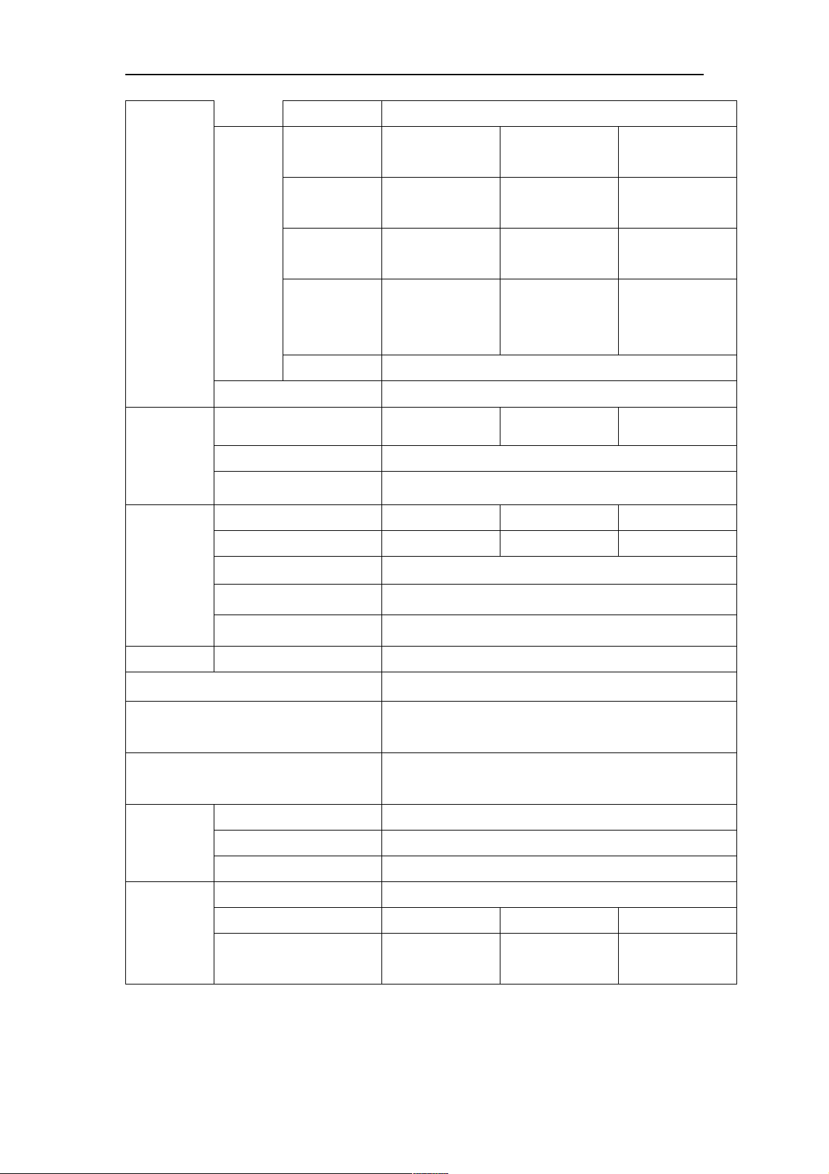
ATEN HDMI Single Display Secure KVM
mm
mm
Function CS1182H CS1184H CS1188H
Computer
Connections
Direct 2 4 8
Max. 2 4 8
Console Connections 1 Direct
Port Selection Pushbutton
1 x 6-pin Mini-DIN Female (Purple)
Keyboard
1 x USB Type A Female (2/4-Port Black; 8-Port White)
Video 1 x HDMI 1.4 Female (Black)
Console
Connectors
Ports
Mouse
1 x 6-pin Mini-DIN Female (Green)
1 x USB Type A Female (2/4-Port Black; 8-Port White)
432 x 205 x 66
mm
Speaker 1 x Mini Stereo Jack Female (Green)
Microphone N/A
28
ATEN Secure KVM User Manual
CAC 1 x USB Type A Female (Black)
Switches
Keyboard/
Mouse
2 x USB Type-B
Female (White)
2 x HDMI 1.4
4 x USB Type-B
Female (White)
4 x HDMI 1.4
8 x USB Type-B
Female (White)
8 x HDMI 1.4
Video
KVM
Female (Black)
2 x USB Type-B
Female (Black)
4 x USB Type-B
Female (Black)
8 x USB Type-B
CAC
Ports
Speaker
Female (White)
2 x Mini Stereo
Jack Female
(Green)
Female (White)
4 x Mini Stereo
Jack Female
(Green)
Female (White)
8 x Mini Stereo
Jack Female
(Green)
Microphone N/A
Power 1 x 3-prong AC Socket
Port 2 x Pushbuttons 4 x Pushbuttons 8 x Pushbuttons
Reset 1 x Semi-recessed Pushbutton
Power 1 x Rocker
On Line / Selected 2 (Orange) 4 (Orange) 8 (Orange)
CAC activated 2 (Green) 4 (Green) 8 (Green)
LEDs
Power 1 (Blue)
Key Lock LED 3 (Green; Num Lock, Caps Lock, Scroll Lock)
Video 1 (Green, on back panel)
Emulation Keyboard/Mouse USB
Video Max. 3840 x 2160 @ 30 Hz (UHD); 1920 x 1080 (FHD)
Scan Interval N/A
I/P Rating 100–240V~ ; 50-60 Hz; 1A
Operating Temp. 0–50°C
Environment
Storage Temp. -20–60°C
Humidity 0–80% RH, Non-condensing
Housing Metal
Physical
Properties
Weight 1.78kg 1.79kg 3.05kg
335 x 164 x 44
335 x 164 x 44
432 x 205 x 66
Dimensions (L x W x H)
mm
mm
mm
29

ATEN Secure KVM User Manual
ATEN HDMI Dual Display Secure KVM
Function CS1142H CS1144H CS1148H
Computer
Connections
Direct 2 4 8
Max. 2 4 8
Console Connections 1 Direct
Port Selection Pushbutton
1 x 6-pin Mini-DIN Female (Purple)
Keyboard
1 x USB Type A Female (2/4-Port Black; 8-Port White)
Video 2 x HDMI 1.4 Female (Black)
Console
1 x 6-pin Mini-DIN Female (Green)
Mouse
Ports
1 x USB Type A Female (2/4-Port Black; 8-Port White)
Speaker 1 x Mini Stereo Jack Female (Green)
Microphone
N/A
CAC 1 x USB Type A Female (Black)
Connectors
Keyboard/
Mouse
2 x USB Type-B
Female (White)
4 x USB Type-B
Female (White)
8 x USB Type-B
Female (White)
Switches
LEDs
4 x HDMI 1.4
8 x HDMI 1.4
16 x HDMI 1.4
Video
KVM Ports
CAC
Speaker
Microphone
Female (Black)
2 x USB Type-B
Female (White)
2 x Mini Stereo
Jack Female
(Green)
Female (Black)
4 x USB Type-B
Female (White)
4 x Mini Stereo
Jack Female
(Green)
N/A
Female (Black)
8 x USB Type-B
Female (White)
8 x Mini Stereo
Jack Female
(Green)
Power 1 x 3-prong AC Socket
Port 2 x Pushbuttons 4 x Pushbuttons 8 x Pushbuttons
Reset 1 x Semi-recessed Pushbutton
Power 1 x Rocker
On Line / Selected 2 (Orange) 4 (Orange) 8 (Orange)
CAC activated 2 (Green) 4 (Green) 8 (Green)
Power 1 (Blue)
Key Lock LED 3 (Green; Num Lock, Caps Lock, Scroll Lock)
Console Video 2 (Green, on back panel)
Emulation Keyboard/Mouse USB
Video Max. 3840 x 2160 @ 30 Hz (UHD); 1920 x 1080 (FHD)
30

ATEN Secure KVM User Manual
Scan Interval N/A
I/P Rating 100–240V~ ; 50-60 Hz; 1A
Operating Temp. 0–50°C
Environment
Storage Temp. -20–60°C
Humidity 0–80% RH, Non-condensing
Housing Metal
Physical
Properties
Weight 2.12kg 2.13kg 3.35kg
335 x 164 x 66
335 x 164 x 66
Dimensions (L x W x H)
ATEN DVI Single Display Secure KVM
mm
mm
Function CS1182D CS1184D CS1188D
Computer
Connections
Direct 2 4 8
Max. 2 4 8
Console Connections 1 Direct
Port Selection Pushbutton
1 x 6-pin Mini-DIN Female (Purple)
Keyboard
1 x USB Type A Female (2/4-Port Black; 8-Port White)
Video 1 x DVI-I Dual Link Female (White)
432 x 205 x 66
mm
Connectors
Console
1 x 6-pin Mini-DIN Female (Green)
Mouse
Ports
1 x USB Type A Female (2/4-Port Black; 8-Port White)
Speaker 1 x Mini Stereo Jack Female (Green)
Microphone
CAC 1 x USB Type A Female (Black)
Keyboard/
Mouse
2 x USB Type-B
Female (White)
2 x DVI-I Dual Link
Video
Female (White)
2 x USB Type-B
KVM Ports
CAC
Female (White)
2 x Mini Stereo
Speaker
Jack Female
(Green)
Microphone
Power 1 x 3-prong AC Socket
N/A
4 x USB Type-B
Female (White)
4 x DVI-I Dual Link
Female (White)
4 x USB Type-B
Female (White)
4 x Mini Stereo
Jack Female
(Green)
N/A
8 x USB Type-B
Female (White)
8 x DVI-I Dual Link
Female (White)
8 x USB Type-B
Female (White)
8 x Mini Stereo
Jack Female
(Green)
31

ATEN Secure KVM User Manual
Port 2 x Pushbuttons 4 x Pushbuttons 8 x Pushbuttons
Switches
Reset 1 x Semi-recessed Pushbutton
Power 1 x Rocker
On Line / Selected 2 (Orange) 4 (Orange) 8 (Orange)
CAC activated 2 (Green) 4 (Green) 8 (Green)
LEDs
Power 1 (Blue)
Key Lock LED 3 (Green; Num Lock, Caps Lock, Scroll Lock)
Video 1 (Green, on back panel)
Emulation Keyboard/Mouse USB
3840 x 2160 @ 30 Hz*; DVI Dual Link: 2560 x 1600; DVI
Video
Single Link: 1920 x 1200; DVI-A: 2048 x 1536
Scan Interval N/A
I/P Rating 100–240V~ ; 50-60 Hz; 1A
Operating Temp. 0–50°C
Environment
Storage Temp. -20–60°C
Humidity 0–80% RH, Non-condensing
Housing Metal
Physical
Properties
Weight 1.78kg 1.79kg 3.05kg
335 x 164 x 44
335 x 164 x 44
Dimensions (L x W x H)
mm
* DVI Secure KVM Switches offer 3840 x 2160 @ 30 Hz video output on compatible HDMI-interfaced
monitors/computers with ATEN DVI-to-HDMI KVM cables
ATEN DVI Dual Display Secure KVM
mm
Function CS1142D CS1144D CS1148D
Computer
Connections
Direct 2 4 8
Max. 2 4 8
Console Connections 1 Direct
Port Selection Pushbutton
1 x 6-pin Mini-DIN Female (Purple)
Keyboard
1 x USB Type A Female (2/4-Port Black; 8-Port White)
Console
Connectors
Video 2 x DVI-I Dual Link Female (White)
Ports
1 x 6-pin Mini-DIN Female (Green)
Mouse
1 x
USB Type A Female (2/4-Port Black; 8-Port White)
432 x 205 x 66
mm
32

ATEN Secure KVM User Manual
Speaker 1 x Mini Stereo Jack Female (Green)
Switches
Microphone
N/A
CAC 1 x USB Type A Female (Black)
Keyboard/
Mouse
2 x USB Type-B
Female (White)
4 x USB Type-B
Female (White)
8 x USB Type-B
Female (White)
16 x DVI-I Dual
Video
4 x DVI-I Dual Link
Female (White)
8 x DVI-I Dual Link
Link Female
Female (White)
(White)
KVM Ports
2 x USB Type-B
4 x USB Type-B
8 x USB Type-B
CAC
Speaker
Microphone
Female (White)
2 x Mini Stereo
Jack Female
(Green)
Female (White)
4 x Mini Stereo
Jack Female
(Green)
N/A
Female (White)
8 x Mini Stereo
Jack Female
(Green)
Power 1 x 3-prong AC Socket
Port 2 x Pushbuttons 4 x Pushbuttons 8 x Pushbuttons
Reset 1 x Semi-recessed Pushbutton
Power 1 x Rocker
On Line / Selected 2 (Orange) 4 (Orange) 8 (Orange)
CAC activated 2 (Green) 4 (Green) 8 (Green)
LEDs
Power 1 (Blue)
Key Lock LED 3 (Green; Num Lock, Caps Lock, Scroll Lock)
Console Video 2 (Green, on back panel)
Emulation Keyboard/Mouse USB
3840 x 2160 @ 30 Hz*; DVI Dual Link: 2560 x 1600; DVI
Video
Single Link: 1920 x 1200; DVI-A: 2048 x 1536
Scan Interval N/A
I/P Rating 100–240V~ ; 50-60 Hz; 1A
Operating Temp. 0–50°C
Environment
Storage Temp. -20–60°C
Humidity 0–80% RH, Non-condensing
Housing Metal
Physical
Properties
Weight 2.12kg 2.13kg 3.35kg
335 x 164 x 66
335 x 164 x 66
432 x 205 x 66
Dimensions (L x W x H)
mm
* DVI Secure KVM Switches offer 3840 x 2160 @ 30 Hz video output on compatible HDMI-interfaced
monitors/computers with ATEN DVI-to-HDMI KVM cables
mm
mm
33

ATEN Secure KVM User Manual
Limited Warranty
IN NO EVENT SHALL THE DIRECT VENDOR'S LIABILITY EXCEED THE PRICE PAID FOR THE PRODUCT FROM
DIRECT, INDIRECT, SPECIAL, INCIDENTAL, OR CONSEQUENTIAL DAMAGES RESULTING FROM THE USE OF
THE PRODUCT, DISK, OR ITS DOCUMENTATION.
The direct vendor makes no warranty or representation, expressed, implied, or statutory with respect to the contents or use of this
documentation, and especially disclaims its quality, performance, merchantability, or fitness for any particular purpose.
The direct vendor also reserves the right to revise or update the device or documentation without obligation to notify any
individual or entity of such revisions, or update. For further inquiries, please contact your direct vendor.
34
 Loading...