

Page 1
USB KVM Extender
CE800B
User Manual
www.aten.com
Page 2
CE800B User Manual
FCC Information
This is an FCC Class A product. In a domestic environment this product may
cause radio interference in which case the user may be required to take
adequate measures.
This equipment has been tested and found to comply with the limits for a Class
A digital device, pursuant to Part 15 of the FCC Rules. These limits are
designed to provide reasonable protection against harmful interference when
the equipment is operated in a commercial environment. This equipment
generates, uses and can radiate radio frequency energy and, if not installed and
used in accordance with the instruction manual, may cause harmful
interference to radio communications. Operation of this equipment in a
residential area is likely to cause harmful interference in which case the user
will be required to correct the interference at his own expense.
RoHS
This product is RoHS compliant.
SJ/T 11364-2006
The following contains information that relates to China.
ii
Page 3

CE800B User Manual
User Information
Online Registration
Be sure to register your product at our online support center:
International http://support.aten.com
North America http://www.aten-usa.com/product_registration
Telephone Support
For telephone support, call this number:
International 886-2-8692-6959
China 86-10-5255-0110
Japan 81-3-5615-5811
Korea 82-2-467-6789
North America 1-888-999-ATEN ext 4988
United Kingdom 44-8-4481-58923
User Notice
All information, documentation, and specifications contained in this manual are subject
to change without prior notification by the manufacturer. The manufacturer makes no
representations or warranties, either expressed or implied, with respect to the contents
hereof and specifically disclaims any warranties as to merchantability or fitness for any
particular purpose. Any of the manufacturer's software described in this manual is sold
or licensed as is. Should the programs prove defective following their purchase, the
buyer (and not the manufacturer , its distributor, or its dealer), assumes the entire cost of
all necessary servicing, repair and any incidental or consequential damages resulting
from any defect in the software.
The manufacturer of this system is not responsible for any radio and/or TV interference
caused by unauthorized modifications to this device. It is the responsibility of the user
to correct such interference.
The manufacturer is not responsible for any damage incurred in the operation of this
system if the correct operational voltage setting was not selected prior to operation.
PLEASE VERIFY THAT THE VOLTAGE SETTING IS CORRECT BEFORE USE.
This ATEN product is specifically designed and manufactured for the operation and
management of computer mainframe and communications equipment used in network
management centers. As such, it may not be completely appropriate for those
environments and sites where special standards for performance and high reliability are
required – such as military equipment, traffic management, nuclear facilities, security
systems, communications equipment, medical facilities, etc.
iii
Page 4

CE800B User Manual
© Copyright 2008–2012 ATEN® International Co., Ltd.
Manual Part No. PAPE-0300-AT2G
Manual Date: 2012-02-23
ATEN and the ATEN logo are registered trademarks of ATEN Internatio nal Co., Ltd. All rights rese rved.
All other brand names and trademarks are the registered property of their respective owners.
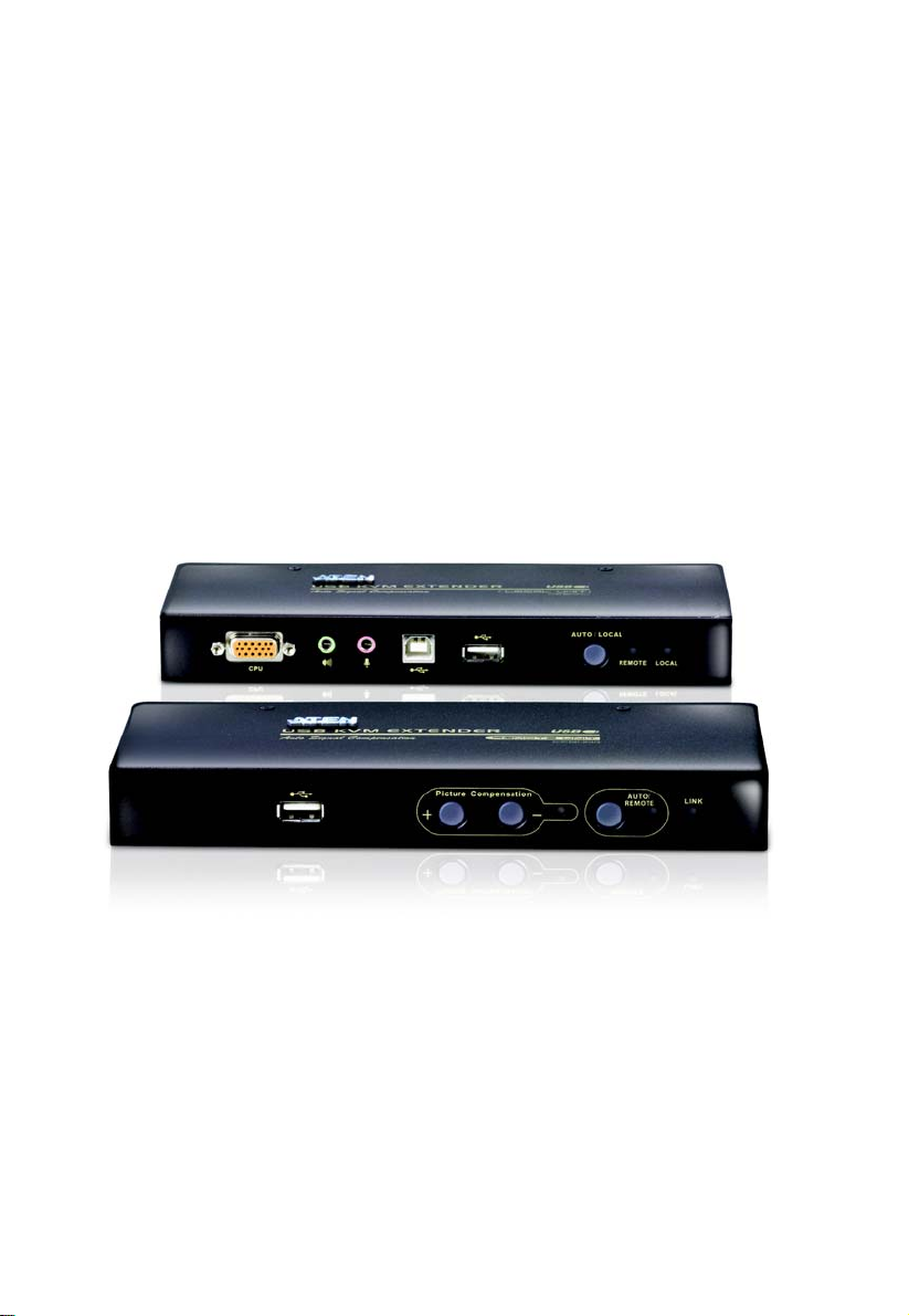
Package Contents
The CE800B USB KVM Extender package contains:
1 CE800
1 CE800
1 Custom KVM Cable (1.8 m)
2 Power Adapters
1 Firmware Upgrade Cable
1 USB Cable (1.8 m)
1 Mounting Kit
1 User Instructions*
1 Grounding Information Card
Check to make sure that all the components are present and that nothing got
damaged in shipping. If you encounter a problem, contact your dealer.
Read this manual thoroughly and follow the installation and operation
procedures carefully to prevent any damage to the unit, and/or any of the
devices connected to it.
BL USB KVM Extender (Local Unit)
BR USB KVM Extender (Remote Unit)
* Features may have been added to the CE800B since this manual was printed.
Please visit our website to download the most up-to-date version of the manual.
iv
Page 5

CE800B User Manual
Contents
FCC Information . . . . . . . . . . . . . . . . . . . . . . . . . . . . . . . . . . . . . . . . . . . . . ii
RoHS. . . . . . . . . . . . . . . . . . . . . . . . . . . . . . . . . . . . . . . . . . . . . . . . . . . . . . ii
SJ/T 11364-2006. . . . . . . . . . . . . . . . . . . . . . . . . . . . . . . . . . . . . . . . . . . . .ii
User Information . . . . . . . . . . . . . . . . . . . . . . . . . . . . . . . . . . . . . . . . . . . . .iii
Online Registration . . . . . . . . . . . . . . . . . . . . . . . . . . . . . . . . . . . . . . . .iii
Telephone Support . . . . . . . . . . . . . . . . . . . . . . . . . . . . . . . . . . . . . . . .iii
User Notice . . . . . . . . . . . . . . . . . . . . . . . . . . . . . . . . . . . . . . . . . . . . . .iii
Package Contents. . . . . . . . . . . . . . . . . . . . . . . . . . . . . . . . . . . . . . . . . . . iv
Contents . . . . . . . . . . . . . . . . . . . . . . . . . . . . . . . . . . . . . . . . . . . . . . . . . . . v
About this Manual . . . . . . . . . . . . . . . . . . . . . . . . . . . . . . . . . . . . . . . . . . . vii
Conventions . . . . . . . . . . . . . . . . . . . . . . . . . . . . . . . . . . . . . . . . . . . . . . .viii
Product Information. . . . . . . . . . . . . . . . . . . . . . . . . . . . . . . . . . . . . . . . . .viii
1. Introduction
Overview. . . . . . . . . . . . . . . . . . . . . . . . . . . . . . . . . . . . . . . . . . . . . . . . . . .1
Features . . . . . . . . . . . . . . . . . . . . . . . . . . . . . . . . . . . . . . . . . . . . . . . . . . .2
System Requirements. . . . . . . . . . . . . . . . . . . . . . . . . . . . . . . . . . . . . . . . .3
Consoles . . . . . . . . . . . . . . . . . . . . . . . . . . . . . . . . . . . . . . . . . . . . . . . .3
Computers. . . . . . . . . . . . . . . . . . . . . . . . . . . . . . . . . . . . . . . . . . . . . . .3
Cables. . . . . . . . . . . . . . . . . . . . . . . . . . . . . . . . . . . . . . . . . . . . . . . . . .3
Operating Systems . . . . . . . . . . . . . . . . . . . . . . . . . . . . . . . . . . . . . . . .4
CE800BL (Local Unit) Front View. . . . . . . . . . . . . . . . . . . . . . . . . . . . . . . .5
CE800BR (Remote Unit) Front View. . . . . . . . . . . . . . . . . . . . . . . . . . . . . .6
CE800BL / CE800BR Rear View . . . . . . . . . . . . . . . . . . . . . . . . . . . . . . . .7
Side View . . . . . . . . . . . . . . . . . . . . . . . . . . . . . . . . . . . . . . . . . . . . . . .7
2. Hardware Setup
Before You Begin . . . . . . . . . . . . . . . . . . . . . . . . . . . . . . . . . . . . . . . . . . . .9
Rack Mounting . . . . . . . . . . . . . . . . . . . . . . . . . . . . . . . . . . . . . . . . . . . . . .9
Installation. . . . . . . . . . . . . . . . . . . . . . . . . . . . . . . . . . . . . . . . . . . . . . . . .11
Grounding . . . . . . . . . . . . . . . . . . . . . . . . . . . . . . . . . . . . . . . . . . . . . .11
Setting Up . . . . . . . . . . . . . . . . . . . . . . . . . . . . . . . . . . . . . . . . . . . . . .13
Standard Installation – CE800B to PC . . . . . . . . . . . . . . . . . . . . . . . .15
Advanced Installation – CE800B to KVM Switch . . . . . . . . . . . . . . . .16
3. Operation
Basic Operation. . . . . . . . . . . . . . . . . . . . . . . . . . . . . . . . . . . . . . . . . . . . .17
Operating Modes. . . . . . . . . . . . . . . . . . . . . . . . . . . . . . . . . . . . . . . . .17
Mode Selection . . . . . . . . . . . . . . . . . . . . . . . . . . . . . . . . . . . . . . . . . .17
Picture Compensation. . . . . . . . . . . . . . . . . . . . . . . . . . . . . . . . . . . . .18
LED Display. . . . . . . . . . . . . . . . . . . . . . . . . . . . . . . . . . . . . . . . . . . . .18
USB Mass Storage . . . . . . . . . . . . . . . . . . . . . . . . . . . . . . . . . . . . . . .19
OSD Operation . . . . . . . . . . . . . . . . . . . . . . . . . . . . . . . . . . . . . . . . . . . . .20
v
Page 6

CE800B User Manual
Overview. . . . . . . . . . . . . . . . . . . . . . . . . . . . . . . . . . . . . . . . . . . . . . . 20
Administrator Main Screen . . . . . . . . . . . . . . . . . . . . . . . . . . . . . . . . .21
OSD Navigation . . . . . . . . . . . . . . . . . . . . . . . . . . . . . . . . . . . . . . . . . 21
Administrator Configuration. . . . . . . . . . . . . . . . . . . . . . . . . . . . . . . . . 22
User Configuration . . . . . . . . . . . . . . . . . . . . . . . . . . . . . . . . . . . . . . . 24
Hotkey Setting Mode . . . . . . . . . . . . . . . . . . . . . . . . . . . . . . . . . . . . . . . . 25
Invoking HSM . . . . . . . . . . . . . . . . . . . . . . . . . . . . . . . . . . . . . . . . . . . 25
Alternate HSM Invocation Keys . . . . . . . . . . . . . . . . . . . . . . . . . . . . .26
Alternate OSD Activation Keys . . . . . . . . . . . . . . . . . . . . . . . . . . . . . .26
Enable / Disable Hotkeys . . . . . . . . . . . . . . . . . . . . . . . . . . . . . . . . . . 27
Keyboard Operating Platform . . . . . . . . . . . . . . . . . . . . . . . . . . . . . . .27
USB Reset . . . . . . . . . . . . . . . . . . . . . . . . . . . . . . . . . . . . . . . . . . . . . 28
Hotkey Summary Table. . . . . . . . . . . . . . . . . . . . . . . . . . . . . . . . . . . . 28
4. Keyboard Emulation
Mac Keyboard. . . . . . . . . . . . . . . . . . . . . . . . . . . . . . . . . . . . . . . . . . . . . .29
Sun Keyboard. . . . . . . . . . . . . . . . . . . . . . . . . . . . . . . . . . . . . . . . . . . . . . 30
5. The Firmware Upgrade Utility
Before You Begin . . . . . . . . . . . . . . . . . . . . . . . . . . . . . . . . . . . . . . . . . . . 31
Starting the Upgrade. . . . . . . . . . . . . . . . . . . . . . . . . . . . . . . . . . . . . . . . . 33
Upgrade Succeeded. . . . . . . . . . . . . . . . . . . . . . . . . . . . . . . . . . . . . . . . .35
Upgrade Failed. . . . . . . . . . . . . . . . . . . . . . . . . . . . . . . . . . . . . . . . . . . . .35
Appendix
Safety Instructions . . . . . . . . . . . . . . . . . . . . . . . . . . . . . . . . . . . . . . . . . .37
General . . . . . . . . . . . . . . . . . . . . . . . . . . . . . . . . . . . . . . . . . . . . . . . . 37
Rack Mounting . . . . . . . . . . . . . . . . . . . . . . . . . . . . . . . . . . . . . . . . . . 39
Technical Support. . . . . . . . . . . . . . . . . . . . . . . . . . . . . . . . . . . . . . . . . . . 40
International . . . . . . . . . . . . . . . . . . . . . . . . . . . . . . . . . . . . . . . . . . . .40
North America. . . . . . . . . . . . . . . . . . . . . . . . . . . . . . . . . . . . . . . . . . .40
Specifications . . . . . . . . . . . . . . . . . . . . . . . . . . . . . . . . . . . . . . . . . . . . . .41
Troubleshooting . . . . . . . . . . . . . . . . . . . . . . . . . . . . . . . . . . . . . . . . . . . . 42
TP Wiring Diagram / TP Pin Assignments . . . . . . . . . . . . . . . . . . . . . . . .42
Clear Login Information . . . . . . . . . . . . . . . . . . . . . . . . . . . . . . . . . . . . . . 43
About SPHD Connectors . . . . . . . . . . . . . . . . . . . . . . . . . . . . . . . . . . . . . 44
Limited Warranty. . . . . . . . . . . . . . . . . . . . . . . . . . . . . . . . . . . . . . . . . . . . 44
vi
Page 7

CE800B User Manual
About this Manual
This User Manual is provided to help you get the most from your CE800B
system. It covers all aspects of installation, configuration and operation. An
overview of the information found in the manual is provided below.
Chapter 1, Introduction, introduces you to the CE800
B USB KVM
Extender system. Its purpose, features and benefits are presented, and its front
and back panel components are described.
Chapter 2, Hardware Setup, describes how to set up your installation.
Chapter 3, Operation, explains the fundamental concepts involved in
operating the CE800
B; provides a complete description of the CE800B's OSD
(On Screen Display), and how to work with it; and details all of the concepts
and procedures involved in the Hotkey operation of your CE800
B installation.
Chapter 4, Keyboard Emulation, provides tables that list the PC to Mac
and PC to Sun keyboard emulation mappings.
Chapter 5, The Firmware Upgrade Utility, explains how to use this
utility to upgrade the CE800
B's firmware with the latest available versions.
An Appendix, provides specifications and other technical information
regarding the CE800
B.
vii
Page 8

CE800B User Manual
Conventions
This manual uses the following conventions:
Monospaced Indicates text that you should key in.
[ ] Indicates keys you should press. For example, [Enter] means to
press the Enter key. If keys need to be chorded, they appear
together in the same bracket with a plus sign between them:
[Ctrl+Alt].
1. Numbered lists represent procedures with sequential steps.
♦
→
Bullet lists provide information, but do not involve sequential steps.
Indicates selecting the option (on a menu or dialog box, for
example), that comes next. For example, Start
open the Start menu, and then select Run.
Indicates critical information.
→ Run means to
Product Information
For information about all ATEN products and how they can help you connect
without limits, visit ATEN on the Web or contact an ATEN Authorized
Reseller. Visit ATEN on the Web for a list of locations and telephone numbers:
International http://www.aten.com
North America http://www.aten-usa.com
viii
Page 9

Chapter 1
Introduction
Overview
The CE800B USB KVM Extender with on-board audio allows access to a
computer system from a remote console (USB keyboard and mouse, monitor,
stereo speakers, and microphone). It is perfect for factory and construction
sites, or any type of installation where the console needs to be in a conveniently
accessible location, but you want the system equipment to reside in a safe place
– away from dust, dirt, and harsh environmental influences.
The CE800
B also is useful for control and security purposes. Store the system
unit in a secure area while at the same time you put the console in a location
that offers convenient access.
Recognizing the increased importance of sound in the computing environment,
the on-board audio feature of the latest CE800
B allows audio (stereo
microphone and stereo speakers) transmissions to be extended to the remote
system along with the KVM data.
The CE800
B USB KVM Extender further improves on previous designs by
using compact Cat 5e cable – the kind commonly used in Ethernet networks –
instead of bulkier, more expensive, standard cables. Cat 5e cabling makes for
a much neater, more convenient, more reliable data transfer connection.
Furthermore, the CE800
B has built-in USB ports that support USB Mass
Storage compliant flash drives. The addition of a Type B USB port on the local
unit means that the flash drive facility is fully supported in both PC-only and
KVM switch installations.
Setup is as easy as can be – simply connect the computer system box and local
console to the Local CE800
B Unit, run the Cat 5e cable to the Remote CE800B
Unit (up to 250 meters away); and plug the remote console into the Remote
Unit.
Note: 1. You can control numerous remote systems from a single console by
combining the CE800
for details on combining a KVM switch in your CE800
B with a KVM switch. See Setting Up, page 13
B installation.
2. If you want to include a touchscreen in your CE800
must purchase an additional USB extender.
B installation, you
1
Page 10

CE800B User Manual
Features
Cat 5e (or higher) cable connects the Local and Remote Units – up to 250
m (825 ft) apart
Dual console operation – control your system(s) from both the local and
remote consoles
Pushbutton selection of the active console
Built-in USB port on both units supports external USB Mass Storage
compliant flash drives for easy file sharing
Special security feature requires login when connecting an external USB
flash drive on the remote unit
Supports VGA, SVGA, and multisync monitors – local monitor supports
DDC; DDC2; DDC2B
High Resolution Video – up to 1920 x 1200@60Hz (30 m); 1600 x
1200@60Hz (150 m); 1024 x 768@60Hz (250 m)
Built-in 8KV/15KV ESD protection and 2KV surge protection
Adjustable gain control – automatically and manually adjusts signal
strength to compensate for distance.
Supports stereo speakers and stereo microphone
Supports Microsoft Intellimouse and the scrolling wheel on most mice
Upgradable firmware
Built-in ASIC for greater reliability and compatibility
2
Page 11

1. Introduction
System Requirements
Consoles
T wo VGA, SVGA, or multisync monitors capable of the highest resolution
that you will be using on any computer in the installation
T wo USB keyboards
Two USB mice
Stereo microphone and stereo speakers (Optional)
Note: If you connect a DDC type monitor to the Local Unit, the monitor
that connects to the Remote Unit must be able to support the highest
video resolution that the DDC monitor can provide.
Computers
The following equipment must be installed on each computer that is to be
connected to the system:
A VGA, SVGA or multisync card
USB Host Controller and Type A USB Port
Cables
For optimum signal integrity and to simplify the layout, we strongly
recommend that you use the high-quality Custom USB KVM Cable that is
provided with this package.
Cat 5e cable is the minimum required to connect the local and remote
CE800
B units. Cable of a lesser standard will result in degraded video
signals. For best performance, we strongly recommend Cat 5e cable.
3
Page 12

CE800B User Manual
Operating Systems
Supported operating systems are shown in the table, below:
OS Version
Windows 2000 and higher
Linux RedHat 7.1 and higher
Mandrake 9.0 and higher
SUSE 10 and higher
UNIX FreeBSD 4.2 and higher
IBM AIX 4.3 and higher
Novell Netware 6.0 and higher
Mac OS 9.0 and higher
4
Page 13
1. Introduction
4
1
2
5 6
3
AUTO / LOCAL
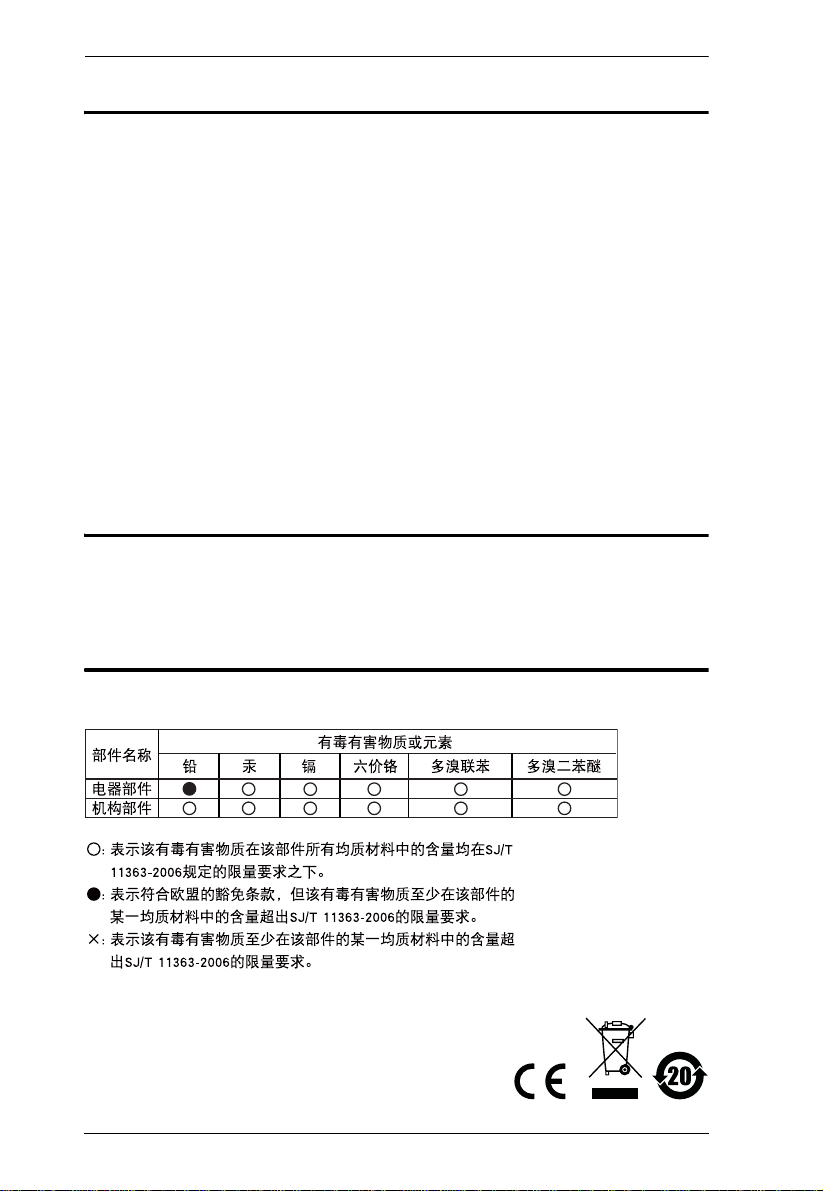
CE800BL (Local Unit) Front View
No. Component Description
1 KVM Port Section This section is made up of a microphone jack,
speaker jack, and KVM (keyboard, video, mouse)
data connectors. The custom cable set that links
the CE800
here. Only KVM cables designed to work with this
switch can be used.
2 USB Type B Port This port provides a CE800
drive support. Connect one end of the USB cable
supplied with the CE800
the other end to a USB Type A port on the local
computer.
If you are using a KVM switch in your CE800
installation, connect the other end of the cable to a
USB Type A port on the KVM switch.
For further details, see Setting Up, page 13.
3 Operating Mode Selection
Pushbutton
Pressing this switch toggles the operating mode
between Auto and Local. See Mode Selection,
page 17 for details.
4 USB Peripheral Port External USB Mass Storage compliant flash drives
plug into this port.
5 Remote LED The Local Unit has two LEDs to indicate the
6 Local LED
operating status of the Local and Remote units
(see LED Display, page18 for details).
BL to your local KVM console plugs in
B installation with flash
B package to this port and
B
5
Page 14
CE800B User Manual
65
1 32
4
AUTO /
REMOTE
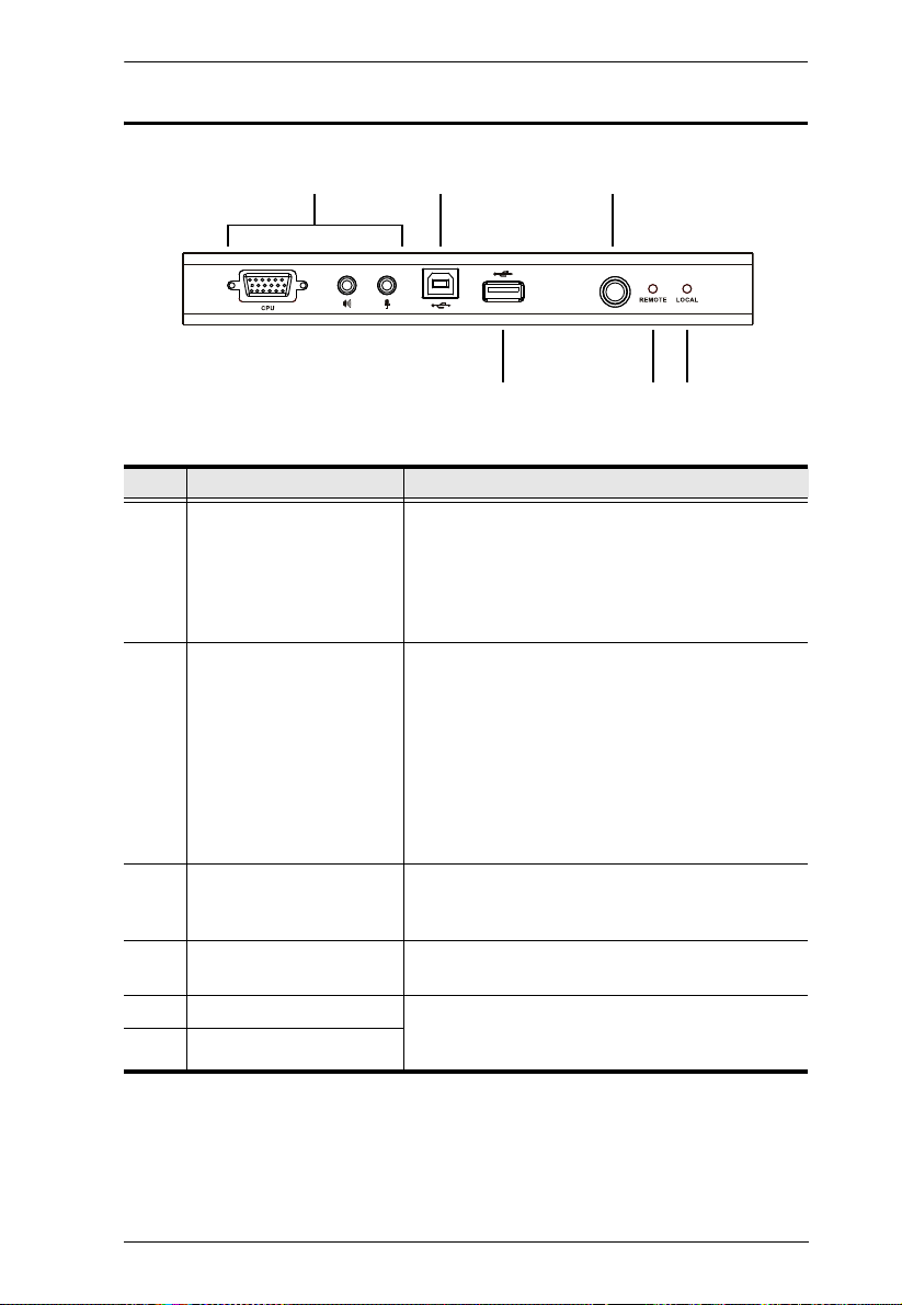
CE800BR (Remote Unit) Front View
No. Component Description
1 USB Peripheral Port External USB Mass Storage compliant flash drives plug
into this port.
2Picture
Compensation
Switches
3Picture
Compensation LED
4 Operating Mode
Selection
Pushbutton
5 Remote LED The Remote LED indicates the operating status of the
6 Link LED Lights to indicate that the CE800
These switches adjust the picture quality of the remote
console. See Picture Compensation, page 18 for details.
Flashes to indicate that picture quality has been
adjusted. See Picture Compensation, page 18 for details.
Pressing this pushbutton toggles the operating mode
between Auto and Remote. See Mode Selection,
page 17 for details.
Remote unit ( See CE800
BR (Remote Unit), page 19, for
details).
CE800
BL
BR is connected to the
6
Page 15
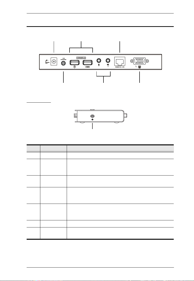
CE800BL / CE800BR Rear View
5
1 3
4
2
6
7
Side View
1. Introduction
No. Component Description
1 Power Jack The cable from the DC Power Adapter plugs into this jack.
2 Keyboard and
Mouse Ports
3 Link Port The Cat 5e cable that connects the Remote and Local units
4 Firmware
Upgrade Port
(Local Unit only)
5Console
Audio Jacks
6 Video Port The console monitors plug into these ports.
7 Grounding
Terminal
The console USB keyboards and mice plug into these ports.
The ports are color coded and marked with an icon to identify
themselves.
plugs into this connector.
The Firmware Upgrade Cable that transfers the firmware
upgrade data from the administrator's computer to the
CE800
The stereo microphone and stereo speakers plug into these
connectors. The ports are color coded and marked with an
icon to identify themselves.
The grounding wire (used to ground the unit) attaches here.
BL plugs in here.
7
Page 16

CE800B User Manual
This Page Intentionally Left Blank
8
Page 17
Chapter 2
1. Important safety information regarding the placement of this
device is provided on page 37. Please review it before proceeding.
2. Make sure that power to all the devices you will be connecting
up have been turned off. You must unplug the power cords of
any computers that have the Keyboard Power On function.
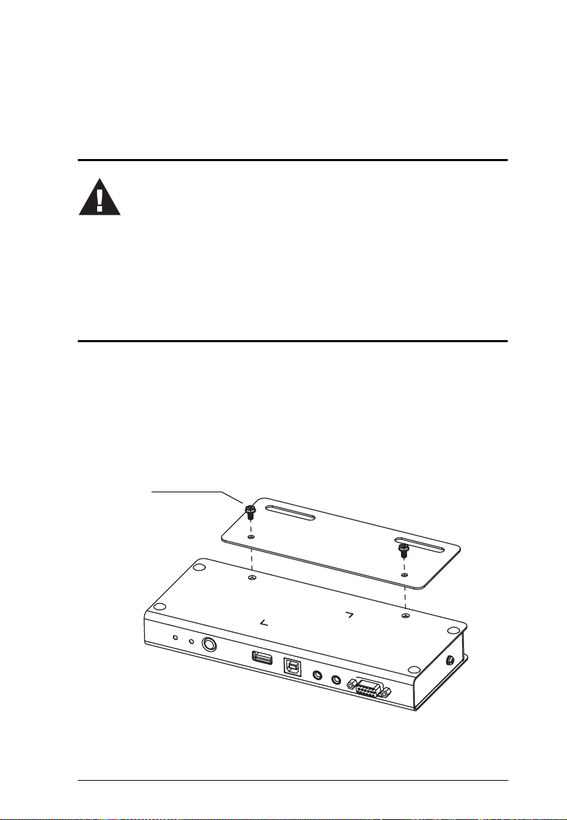
Philips hex head
M3 x 8
Hardware Setup
Before You Begin
Rack Mounting
For convenience and flexibility, the CE800B can be mounted on a system rack.
To rack mount the unit do the following:
1. Using the screws provided with the Mounting Kit, screw the mount ing
bracket into the bottom of the unit as shown in the diagram below.
9
Page 18

CE800B User Manual
2. Screw the bracket into any convenient location on the rack.
Note: The rack screws are not provided. We recommend that you use M5
x 12 Phillips Type I cross, recessed type screws.
10
Page 19

2. Hardware Setup
STP Cable
(Cat 5 or higher)
up to 250 m
AUTO / LOCAL
Installation
Grounding
To prevent damage to your installation it is important that all devices are
properly grounded.
1. Use two grounding wires to ground both units by connecting one end of
the wire to the grounding terminal, and the other end of the wire to a
suitable grounded object.
2. Make sure that the computer that the CE800
that the CE800
3. See the Grounding Information card that came with this package for
proper grounding details.
BR connects to are properly grounded.
BL connects to and the monitor
11
Page 20

CE800B User Manual
4. For increased grounding protection, use STP (shielded twisted pair) cable
to connect the local and remote units. There are two methods that can be
used:
a) In addition to the eight paired wires, STP cable also contains a
grounding wire. Solder this wire to the RJ-45 connector as shown in the
diagram below:
b) The second method is to use the STP cable shielding for grounding. In
this case, make sure that the shielding makes tight contact with the top
inside of the RJ-45 connector as shown in the diagram below:
In either case, make sure that the sides of the RJ-45 connector make tight
contact with the grounding contacts on the sides of the RJ-45 port as
shown in the diagram below:
12
Page 21

2. Hardware Setup
Setting Up
Setting up the USB KVM Extender System is simply a matter of plugging in
the cables. Refer to the diagrams on the following pages as you perform the
following steps (the diagram numbers correspond to the numbers of the steps):
1. Plug the cables from the local console devices (mouse, keyboard, monitor,
microphone and speakers) into their ports on the rear panel of the Local
Unit (CE800
to identify themselves.
2. Plug the KVM connectors on the custom KVM cable provided with this
package into the KVM ports on the CE800
For a standard CE800
If you are combining a KVM switch with your CE800
progress to 4 and refer to the diagram on page 16.
BL). The connectors are color coded and marked with an icon
BL’s front panel.
B-to-PC installation, progress to 3.
B installation,
3. For a standard CE800
B-to-PC installation:
a) Plug the connectors on the other end of the KVM cable into the
appropriate ports on the computer system. The connectors are color
coded and marked with an icon to identify themselves.
b) Next, use the USB cable provided with the CE800
the USB T ype B port on the front of the CE800
B package to connect
BL to a USB T ype A port
on the computer.
4. For a CE800
B-to-KVM switch installation:
a) Plug the connectors on the other end of the KVM cable into the
appropriate ports on the Console section of the KVM switch. The
connectors are color coded and marked with an icon to identify
themselves.
b) Next, use the USB cable provided with the CE800
the USB Type B port on the front of the CE800
B package to connect
BL to the USB Type A
keyboard port on the KVM switch.
Note: T o ensure that the CE800B’s keyboard hotkey function is supported,
make sure that the USB cable is connected to the keyboard USB port
on the KVM switch and not the mouse USB port.
(Continues on next page.)
13
Page 22

CE800B User Manual
5. Connect one end of a Cat 5e twisted pair cable to the Link port on the
CE800
BL; connect the other end of the Cat 5e twisted pair cable into the
Link port on the CE800
BR.
Note: Cat 5e cable is not supplied with this package. It requires a separate
purchase. The cable length can be up to 250 m (820 ft).
6. Plug the cables from the remote console devices (mouse, keyboard,
monitor, microphone and speakers) into their ports on the rear panel of the
Remote Unit (CE800
BR).
7. Connect one of the power adapters provided with this package into an AC
source; connect the adapter's power cable to the Power Jack on the CE800
BL.
8. Connect the other power adapter provided with this package into an AC
source; connect the adapter's power cable to the Power Jack on the CE800
BR.
9. If you are using USB Mass Storage compliant flash drives, plug them into the
USB ports on the Local and Remote Unit’s front panels. See USB Mass
Storage, page 19
14
Page 23

Standard Installation – CE800B to PC
4
1
CE800BL (rear)
3a
5
CE800BR (rear)
6
7
Cat 5e Cable
up to 250 m
2
CE800BL (front)
Custom KVM cable
USB Cable
3b
9
CE800BR (front)
9
2. Hardware Setup
15
Page 24

CE800B User Manual
CE800BL (front)
Custom KVM cable
USB Cable
USB KVM Switch (rear)
4b
4a
Advanced Installation – CE800B to KVM Switch
16
Page 25

Chapter 3
Operation
Basic Operation
Operating Modes
The CE800B USB KVM Extender utilizes three operating modes: Auto, Local,
and Remote, as described in the table below:
Mode Description
Local Only the local console has complete access. Although operators
at both consoles can see the display, only the local console
operator has keyboard and mouse access and control.
Remote Only the remote console has complete access. Although
Auto Both consoles have access but neither has complete input
Mode Selection
The Operating Mode Selection Switch, located on each unit’s front panel,
controls the operating mode of the CE800
Pressing the switch toggles the operating mode as follows:
operators at both consoles can see the display, only the remote
console operator has keyboard and mouse access and control.
control. The first console to create keyboard or mouse input
takes control. Following this, if there is no input for five seconds,
the CE800
B goes back to Auto Mode.
B USB KVM Extender system.
Switch Action
Local (CE800BL) Selection
Switch
Remote (CE800
Selection Switch
BR)
T oggles between Auto and Local. In Local Mode, only the
local console has keyboard and mouse access and
control of the computer (or computers via KVM switch).
Toggles between Auto and Remote. In R emote Mode,
only the remote console has keyboard and mouse
access and control of the computer (or computers via
KVM switch).
When the system is in Local Mode, the Remote unit’s selection switch is
inactive. Pressing it has no effect – the Remote operator cannot take over
control. The Remote selection switch only becomes active after the Local
selection switch is pressed to put the system back into Auto Mode.
17
Page 26

CE800B User Manual
Likewise, if the system is in Remote Mode, the Local unit’s selection switch is
inactive – the Local operator cannot take over control. The Local selection
switch only becomes active after the Remote selection switch is pressed to put
the system back into Auto Mode.
Picture Compensation
The quality of the video display can deteriorate with distance. The Picture
Compensation switches adjust the picture quality of the remote console.
Depending on the distance from the console, if it becomes necessary to adjust
the video signal, press the plus button (+) to increase the video signal gain;
press the minus button (-) to decrease the video signal gain.
LED Display
The CE800B Local and Remote Units have front panel LEDs to indicate their
operating status, as shown in the following tables:
CE800
BL (Local Unit)
LED Status Indication
Local On Local Mode is in effect. The Local console has keyboard
and mouse input control.
Off Remote Mode is in effect. The Remote console has
keyboard and mouse input control.
Flashing Auto Mode is in effect. The first console to establish
keyboard or mouse input takes control.
Remote On Remote Mode is in effect. The Remote console has
keyboard and mouse input control.
Off Local Mode is in effect. The Local console has keyboard
and mouse input control.
Flashing Auto Mode is in effect. The first console to establish
keyboard or mouse input takes control.
18
Page 27

3. Operation
CE800BR (Remote Unit)
LED Status Indication
Remote On Remote Mode is in effect. The Remote console has
Off Local Mode is in effect. The Local console has
Flashing Auto Mode is in effect. Neither console has keyboard
Link On The CE800
Off The CE800BR is not connected to the CE800BL.
Compensation Flashing A picture compensation button has been pushed (+ or
Steady Gain adjustment has been completed and saved.
keyboard and mouse input control.
keyboard and mouse input control.
and mouse input control. The first console to establish
keyboard or mouse input takes control. Following this,
if there is no input for five seconds, the CE800
back to Auto Mode.
BR is connected to the CE800BL.
–) and the CE800
B is adjusting the gain.
B goes
USB Mass Storage
Both the CE800BL and the CE800BR have a built-in USB port that complies
with the USB Mass Storage specification and supports USB Mass Storage
compliant flash drives, allowing easy and convenient file transfer.
When you plug a USB Mass Storage complaint flash drive into either unit’s
USB port, it shows up as a removable drive on the computer.
As a security measure, to help prevent unauthorized file transfers, if a flash
drive is plugged into the USB port of the Remote unit, the OSD login screen
comes up (see page 20). The operator must log in with a valid username and
password before being able to continue.
19
Page 28

CE800B User Manual
OSD Operation
Overview
The CE800B USB KVM Extender provides a convenient menu driven On
Screen Display (OSD) to handle its configuration parameters. All procedures
start from the OSD Main Screen. To pop up the Main Screen:
1. Tap the OSD Hotkey (Scroll Lock) twice.
Note: [Scroll Lock] is the default OSD hotkey. You can optionally change
the hotkey to the Ctrl key (see OSD HOTKEY, page 22, and see
Alternate OSD Activation Keys, page 26).
The login dialog box appears:
2. Key in a valid username and password, then press [Enter].
Note: If this is the first time that the OSD is being run, or if the password
function has not been set, simply press [Enter]. The OSD Main
Screen comes up in Administrator Mode. In this mode, you have
Administrator privileges, with access to all Administrator and User
functions, and can set up operations (including password
authorization for the future), as you would like.
20
Page 29

3. Operation
Administrator Main Screen
After you log in to the OSD, if you are the administrator, a screen similar to the
one below appears:
ESC : EXIT
ENTER : SELECT
ADMINISTRATOR
SET USERNAME AND PASSWORD
OSD HOTKEY
HOTKEY COMMAND MODE (ON)
HOTKEY
USER AUTHENTICATION (ON)
RESTORE DEFAULT VALUES
SET OPERATING SYSTEM
SET KEYBOARD LANGUAGE
Note: If you are an ordinary user, see User Configuration, page 24
: UP X
: DOWN
OSD Navigation
The following principles govern the way you navigate through the OSD:
To di smiss the menu, and deactivate the OSD, Click the X at the upper
right corner of the OSD Window; or press [Esc].
To move up or down through the list one line at a time, Click the Up and
Down Triangle symbols () or use the Up and Down Arrow Keys.
T o select a menu item click it or move the highlight bar to it with the arrow
keys, then press [Enter].
If a submenu appears, make your choice either by double clicking it, or
moving the highlight bar to it, th en pressing [Enter]. An icon of a pointing
finger indicates the currently selected choice.
21
Page 30

CE800B User Manual
Administrator Configuration
The configuration settings that the administrator is allowed to make are
explained in the following table:
Setting Function
SET USERNAME AND
PASSWORD
OSD HOTKEY Selects which Hotkey activates the OSD function:
HOTKEY COMMAND
MODE
HOTKEY Selects which combination activates Hotkey Setting
USER AUTHENTICATION If this setting is On, users have to provide a Username
This function is used to set Usernames and Passwords
for the Administrator and Users:
1. One Administrator and four User passwords can be
set.
2. After you select the Administrator field or one of the
User fields, a screen that allows you to key in your
username and password appears. The username and
password may be up to 12 characters long, and can
consist of any combination of letters and numbers.
3. For each individual, key in the Username and
Password, then press [Enter].
To modify or delete a previous Username and/or
Password, use the backspace key to erase individual
letters or numbers.
[Scroll Lock] [Scroll Lock] or [Ctrl] [Ctrl].
Since the Ctrl key combination may conflict with
programs running on the computers.
The default is the Scroll Lock combination.
Enables / Disables the Hotkey Command function. If the
hotkey combinations conflict with programs running on
the computers, you may want to disable hotkey operation
by turning Hotkey Command Mode Off.
The default is On, which allows hotkey operation of the
switch.
Mode (HSM):
[Num Lock] + [–] or [Ctrl] + [F12]
The default is [Num Lock] + [–]
See Hotkey Setting Mode, page 25 for further details.
and Password when they plug a flash drive into the USB
port of the Remote unit.
The default is On.
22
Page 31

3. Operation
Setting Function
RESTORE DEFAULT
VALUES
Selecting Y (Yes) undoes all changes and returns the
CE800
B’s setup to the original factory default settings.
SET OPERATING SYSTEM This function specifies the operating platform of the
computer attached to the CE800
BL. Choices are Win,
Mac, Sun, and SPC*.
The default is Win
SET KEYBOARD
LANGUAGE
Selects the keyboard layout used by the computer
connected to the CE800
B. Choices are Auto, English,
French, German, and Japanese.
Auto automatically detects the keyboard layout set for
the computer and sets the CE800
B accordingly.
The default is Auto.
* SPC stands for Special Case. For certain operating systems (such as FSBD),
you may need to choose this option if you run into startup problems. If this
occurs, please contact technical support for further information.
23
Page 32

CE800B User Manual
User Configuration
The CE800B USB KVM Extender supports up to four user accounts in addition
to the administrator. When users invoke the OSD, they get an OSD Main
screen allows them to modify some of the configuration settings made by the
administrator.
The User OSD Main Screen looks similar to the one, below:
ESC : EXIT
ENTER : SELECT
USER1
CHANGE PASSWORD
HOTKEY COMMAND MODE (ON)
HOTKEY
SET OPERATING SYSTEM
: UP X
: DOWN
The configuration settings that users are allowed to make are explained in the
table below:
Setting Function
CHANGE PASSWORD Users can use this function to change the password that
was assigned to them by the administrator.
HOTKEY COMMAND
MODE
HOTKEY
SET OPERATING SYS TEM
24
These settings are the same as the ones described
under Administrator Configuration, page 22.
Page 33

3. Operation
Hotkey Setting Mode
In addition to the OSD, the administrator and users can also use hotkey
combinations to configure a number of the CE800
working environment parameters. All Hotkey operations begin by invoking
Hotkey Setting Mode (HSM).
Invoking HSM
To invoke HSM, do the following:
1. Hold down [Num Lock].
2. Press and release [minus].
3. Release [Num Lock].
Note: There is an alternative key combination to invoke HSM (see
Alternate HSM Invocation Keys, page 26).
When Hotkey Mode is active:
The Caps Lock, and Scroll Lock LEDs flash in succession to indicate that
HSM is in effect. They stop flashing and revert to normal status when you
exit HSM.
A Command Line appears on the monitor screen. The command line
prompt is the word Hotkey: in yellow text on a blue background. Hotkey
information that you key in displays on the command line.
Ordinary keyboard and mouse functions are suspended – only Hotkey
compliant keystrokes and mouse clicks (described in the sections that
follow), can be input.
At the conclusion of some hotkey operations, you automatically exit
hotkey mode. With some operations, you must exit manually. T o exit HSM
manually, press [Esc] or [Spacebar].
B USB KVM Extender’s
25
Page 34

CE800B User Manual
Alternate HSM Invocation Keys
An alternate set of HSM invocation keys is provided in case the default set
conflicts with programs running on the computers.
To switch to the alternate HSM invocation set, do the following:
1. Invoke HSM (see page 25).
2. Press and release [H].
The HSM invocation keys become the Ctrl key (instead of Num Lock) and the
F12 key (instead of minus).
Note: This procedure is a toggle between the two methods. To revert back to
the original [Num Lock] [Minus] method, invoke HSM, then press and
release the H key again.
Alternate OSD Activation Keys
The OSD activation method can be changed from tapping the Scroll Lock key
twice to tapping the Ctrl key twice ([Ctrl] [Ctrl]). To change the OSD
activation method, do the following:
1. Invoke HSM (see page 25).
2. Press and release [T].
Note: 1. This procedure is a toggle between the two methods. To revert back
to the original [Scroll Lock] [Scroll Lock] method, invoke HSM, then
press and release the T key again.
2. For Mac systems we recommend using [Ctrl] [Ctrl] as the OSD
activation keys since Scroll Lock is used to emulate F14 in PC to Mac
keyboard emulation (see Keyboard Emulation, page 29).
26
Page 35

3. Operation
Enable / Disable Hotkeys
In case a conflict occurs with programs running on the computer, you may wish
to disable the hotkey function. To disable the hotkey function do the following:
1. Invoke HSM (see page 25).
2. Press and release [X] [Enter].
Note: This procedure is a toggle between enabling / disabling the hotkey
function. To revert back to the original enabled status, invoke HSM,
then press and release the X and Enter keys again.
Keyboard Operating Platform
The CE800B's default configuration is for a PC Compatible keyboard operating
platform. If you have a Mac or a Sun on your installation, you can change the
keyboard operating platform as follows:
3. Invoke HSM (see page 25).
4. Press and release the appropriate Function key (see table).
Key Operation
[F1] Sets the PC compatible keyboard operating platform for the port
that currently has the KVM focus.
[F2] Sets the Mac keyboard operating platform for the port that currently
has the KVM focus.
[F3] Sets the Sun keyboard operating platform for the port that currently
has the KVM focus.
Note: 1. The brackets indicate the keys you should press. Simply press the
indicated keys – do not type the brackets.
2. After completing a setting, you automatically exit HSM.
27
Page 36

CE800B User Manual
USB Reset
Sometimes the USB keyboard and mouse connection to the CE800B needs to
be reset. Instead of unplugging and replugging them, a hotkey combination can
perform the reset, as follows:
1. Invoke HSM (see page 25).
2. Press and release [F5].
Hotkey Summary Table
After invoking HSM (see page 25), key in one of the following keys to perform
the corresponding function:
Key Function
[H] T oggles between the default ([Num Lock] [–]) and alternate
[T] Toggles between the default ([Scroll Lock] [Scroll Lock])
[X] [Enter] Toggles between Enabling / Disabling the hotkey function.
[F1] Sets the PC compatible keyboard operating platform for
[F2] Sets the Mac compatible keyboard operating platform for
[F3] Sets the Sun keyboard operating platform for the port that
[F5] Resets the USB keyboard and mouse.
([Ctrl] [F12]) Hotkey invocation keys.
and alternate ([Ctrl] [Ctrl]) OSD invocation keys.
the port that currently has the KVM focus.
the port that currently has the KVM focus.
currently has the KVM focus.
Note: The brackets indicate the keys you should press. Simpl y press the
indicated keys – do not type the brackets.
28
Page 37

Chapter 4
Keyboard Emulation
Mac Keyboard
The PC compatible (101/104 key) keyboard can emulate the functions of the
Mac keyboard. The emulation mappings are listed in the table below.
PC Keyboard Mac Keyboard
[Shift] Shift
[Ctrl] Ctrl
[Ctrl] [1]
[Ctrl] [2]
[Ctrl] [3]
[Ctrl] [4]
[Alt] Alt
[Print Screen] F13
[Scroll Lock] F14
=
[Enter] Return
[Backspace] Delete
[Insert] Help
[Ctrl]
F15
Note: When using key combinations, press and release the first key (Ctrl),
then press and release the activation key.
29
Page 38

CE800B User Manual
-
Sun Keyboard
The PC compatible (101/104 key) keyboard can emulate the functions of the
Sun keyboard when the Control key [Ctrl] is used in conjunction with other
keys. The corresponding functions are shown in the table below.
PC Keyboard Sun Keyboard
[Ctrl] [T] Stop
[Ctrl] [F2] Again
[Ctrl] [F3] Props
[Ctrl] [F4] Undo
[Ctrl] [F5] Front
[Ctrl] [F6] Copy
[Ctrl] [F7] Open
[Ctrl] [F8] Paste
[Ctrl] [F9] Find
[Ctrl] [F10] Cut
[Ctrl] [1]
[Ctrl] [2]
[Ctrl] [3]
[Ctrl] [4]
[Ctrl] [H] Help
+
Compose
Note: When using key combinations, press and release the first key (Ctrl),
then press and release the activation key.
30
Page 39

Chapter 5
The Firmware Upgrade Utility
The Windows-based Firmware Upgrade Utility (FWUpgrade.exe) provides a
smooth, automated process for upgrading the KVM switch's firmware.
The Utility comes as part of a Firmware Upgrade Package that is specific for
each device. New firmware upgrade packages are posted on our web site as
new firmware revisions become available. Check the web site regularly to find
the latest packages and information relating to them:
http://www.aten.com
Before You Begin
To prepare for the firmware upgrade, do the following:
1. Unplug the power adapters from both units, and disconnect the KVM
cable (to the local computer) from the CE800
2. Go to our Internet support site and choose the model name of your device
(CE800
3. Choose the Firmware Upgrade Package you want to install (usually the
most recent), and download it to your computer.
B) to get a list of available Firmware Upgrade Packages.
BL’s front panel.
4. Use the Firmware Upgrade Cable provided with this unit to connect a
COM port on your computer to the CE800
BL’s Firmware Upgrade Port.
31
Page 40

CE800B User Manual
5. Make sure both units are connected by the Cat 5e cable, then plug in the
Remote unit’s power adapter.
6. Press and hold the Local unit’s Selection button, then plug in the Local
unit’s power adapter.
7. Wait until both green front panel LEDs on the Local unit are flashing on
and off, then release the Selection button.
8. Make sure the orange LED on the front panel of the Remote unit is on
(indicating that Firmware Upgrade Mode is in effect.
Note: If the LED is not on, or it is blinking, the unit is not ready to be
upgraded. You must repeat steps 6 and 7.
32
Page 41

5. The Firmware Upgrade Utility
Starting the Upgrade
To upgrade your firmware:
1. Run the downloaded Firmware Upgrade Package file – either by double
clicking the file icon, or by opening a command line and entering the full
path to it.
The Firmware Upgrade Utility Welcome screen appears:
Note: The screens shown in this section are for reference only. The
wording and layout of the actual screens put up by the Firmware
Upgrade Utility may vary slightly from these examples.
2. Read and Agree to the License Agreement (enable the I Agree radio
button).
(Continues on next page.)
33
Page 42

CE800B User Manual
3. Click Next to continue. The Firmware Upgrade Utility main screen appears:
The Utility inspects your installation. All the devices capable of being
upgraded by the package are listed in the Device List panel.
4. As you select a device in the list, its description appears in the Device
Description panel.
5. After you have made your device selection(s), Click Next to perform the
upgrade.
If you enabled Check Firmware Version, the Utility compares the device's
firmware level with that of the upgrade files. If it finds that the device's
version is higher than the upgrade version, it brings up a dialog box
informing you of the situation and gives you the option to Continue or
Cancel.
If you did not enable Check Firmware Version, the Utility installs the
upgrade files without checking whether or not they are a higher level.
As the Upgrade proceeds, status messages appear in the Status Messages
panel, and the progress toward completion is shown on the Progress bar.
34
Page 43

5. The Firmware Upgrade Utility
Upgrade Succeeded
After the upgrade has completed, a screen appears to inform you that the
procedure was successful:
Click Finish to close the Firmware Upgrade Utility.
After successfully upgrading the firmware, the switches automatically exit
Firmware Upgrade Mode. Please power the unit off and on after you have
exited Firmware Upgrade Mode.
Upgrade Failed
If the Upgrade Succeeded screen does not appear, then the upgrade failed to
complete successfully. You should repeat the upgrade procedure from the
beginning.
35
Page 44

CE800B User Manual
This Page Intentionally Left Blank
36
Page 45

Appendix
Safety Instructions
General
Read all of these instructions. Save them for future reference.
Follow all warnings and instructions marked on the device.
To prevent damage to your installation it is important that all devices are
properly grounded.
Do not place the device on any unstable surface (cart, stand, table, etc.). If
the device falls, serious damage will result.
Do not use the device near water.
Do not place the device near, or over, radiators or heat registers.
The device cabinet is provided with slots and openings to allow for
adequate ventilation. To ensure reliable operation, and to protect against
overheating, these openings must never be blocked or covered.
The device should never be placed on a soft surface (bed, sofa, rug, etc.) as
this will block its ventilation openings. Likewise, the device should not be
placed in a built in enclosure unless adequate ventilation has been
provided.
Never spill liquid of any kind on the device.
Unplug the device from the wall outlet before cleaning. Do not use liquid
or aerosol cleaners. Use a damp cloth for cleaning.
The device should be operated from the type of power source indicated on
the marking label. If you are not sure of the type of power available,
consult your dealer or local power company.
Do not allow anything to rest on the power cord or cables. Route the
power cord and cables so that they cannot be stepped on or tripped over.
If an extension cord is used with this device make sure that the total of the
ampere ratings of all products used on this cord does not exceed the
extension cord ampere rating. Make sure that the total of all products
plugged into the wall outlet does not exceed 15 amperes.
To help protect your system from sudden, transient increases and
decreases in electrical power, use a surge suppressor, line conditioner, or
un-interruptible power supply (UPS).
37
Page 46

CE800B User Manual
Position system cables and power cables carefully; Be sure that nothing
rests on any cables.
When connecting or disconnecting power to hot-pluggable power
supplies, observe the following guidelines:
Install the power supply before connecting the power cable to the
power supply.
Unplug the power cable before removing the power supply.
If the system has multiple sources of power, disconnect power from the
system by unplugging all power cables from the power supplies.
Never push objects of any kind into or through cabinet slots. They may
touch dangerous voltage points or short out parts resulting in a risk of fire
or electrical shock.
Do not attempt to service the device yourself. Refer all servicing to
qualified service personnel.
If the following conditions occur, unplug the device from the wall outlet
and bring it to qualified service personnel for repair.
The power cord or plug has become damaged or frayed.
Liquid has been spilled into the device.
The device has been exposed to rain or water.
The device has been dropped, or the cabinet has been damaged.
The device exhibits a distinct change in performance, indicating a need
for service.
The device does not operate normally when the operating instructions
are followed.
Only adjust those controls that are covered in the operating instructions.
Improper adjustment of other controls may result in damage that will
require extensive work by a qualified technician to repair.
38
Page 47

Rack Mounting
Before working on the rack, make sure that the stabilizers are secured to
the rack, extended to the floor, and that the full weight of the rack rests on
the floor. Install front and side stabilizers on a single rack or front
stabilizers for joined multiple racks before working on the rack.
Always load the rack from the bottom up, and load the heaviest item in the
rack first.
Make sure that the rack is level and stable before extending a device from
the rack.
Use caution when pressing the device rail release latches and sliding a
device into or out of a rack; the slide rails can pinch your fingers.
After a device is inserted into the rack, carefully extend the rail into a
locking position, and then slide the device into the rack.
Do not overload the AC supply branch circuit that provides power to the
rack. The total rack load should not exceed 80 percent of the branch circuit
rating.
Ensure that proper airflow is provided to devices in the rack.
Do not step on or stand on any device when servicing other devices in a
rack.
39
Page 48

CE800B User Manual
Technical Support
International
For online technical support – including troubleshooting, documentati on,
and software updates: http://support.aten.com
For telephone support, see Telephone Support, page ii i
North America
Email Support support@aten-usa.com
Online
Technical
Support
Telephone Support 1-888-999-ATEN ext 4988
When you contact us, please have the following information ready beforehand:
Product model number, serial number, and date of purchase.
Your computer configuration, incl uding operating system, revision level,
expansion cards, and software.
Any error messages displayed at the time the error occurred.
The sequence of operations that led up to the error.
Any other information you feel may be of help.
Troubleshooting
Documentation
Software Updates
http://www.aten-usa.com/support
40
Page 49

Specifications
Function CE800BL CE800BR
Computer Connections 1 N/A
Connectors Console Keyboard 1 x USB Ty pe A Female (White)
Video 1 x HDB-15 Female (Blue)
Mouse 1 x USB Type A Female (White)
Speaker 1 x Mini Stereo Jack (Green)
Microphone 1 x Mini Stereo Jack (Pink)
KVM
Ports
F/W Upgrade 1 x 4-conductor 3.5 mm jack N/A
Power 1 x DC Jack (Black)
Unit to Unit (Link) 1 x RJ-45
Pushbuttons Operating Mode
LEDs Local 1 (Green) N/A
Power Consumption DC 5.0 V; 6.0 W
Video 1920 x 1200 @ 60 Hz, 30 m
Environment Operating Temp. 0–50ºC
Physical
Properties
Selection
Picture Compensation N/A 2 x Pushbutton
Remote 1 (Green) 1 (Green)
Link N/A 1 (Green)
Compensation N/A 1 (Orange)
Storage Temp. -20–60ºC
Humidity 0–80% RH
Housing Metal
Weight 0.50 kg 0.49 kg
Dimensions (L x W x H) 20.00 x 8.00 x 2.50 cm
Keyboard /
Video /
Mouse
USB Port 1 x USB Type B (Female)
Speaker 1 x Mini Stereo Jack (Green) N/A
Microphone 1 x Mini Stereo Jack (Pink) N/A
1 x SPHD-15 Female
(Yellow)
1 x USB Type A (Female)
1 x Pushbutton
1600 x 1200 @ 60 Hz, 150 m
1024 x 768 @ 60 Hz, 250 m
1 x USB Type A (Female)
N/A
41
Page 50

CE800B User Manual
JACK POSITIONS
PAIR 2 PAIR 1
PAIR 3
PAIR 4
T568B
AT&T 258A
123456 78
W-O O W-G Bl W-Bl G W-Br Br
Troubleshooting
Operation problems can be due to a variety of causes. The first step in solving
them is to make sure that all cables are securely attached and seated completely
in their ports.
In addition, updating the product’s firmware may solve problems that have
been discovered and resolved since the prior version was released. If your
product is not running the latest firmware version, we strongly recommend that
you upgrade. See The Firmware Upgrade Utility, page 31, for upgrade details.
Problem Action
No video Make sure that all cables are securely plugged into
their ports.
Poor video quality. The video quality can be improved by reducing the
refresh rate.
Touchscreen does not work. To include a touchscreen in your CE800
Keyboard hotkeys do not work
when combining a KVM
switch in the installation.
you must purchase an additional USB extender.
Check that the USB cable that connects to the KVM
switch is connected to the Type A keyboard port and
not the mouse port.
B installation,
TP Wiring Diagram / TP Pin Assignments
42
Pin Assignment Pin Assignment
1 /V OUT B 5 V OUT R
2 V OUT B 6 V OUT G
3/V OUT G 7/DO
4/V OUT R 8DO
Page 51

Clear Login Information
If you are unable to perform an Administrator login (because the Username and
Password information has become corrupted or you have forgotten it, for
example) you can clear the login information with the following procedure:
1. Power off the CE800
B and remove its housing.
2. Short the jumper labeled J7.
3. Power on the switch.
The on screen display will show a message informing you that the
password information has been cleared.
4. Power off the switch.
5. Remove the jumper cap from J7.
6. Close the housing and start the CE800
B back up.
After you start back up, you can use the default Username and Password (see
Overview, page 20) to log in.
43
Page 52

CE800B User Manual
Limited Warranty
IN NO EVENT SHALL THE DIRECT VENDOR'S LIABILITY EXCEED THE PRICE PAID
FOR THE PRODUCT FROM DIRECT, INDIRECT, SPECIAL, INCIDENTAL, OR
CONSEQUENTIAL DAMAGES RESULTING FROM THE USE OF THE PRODUCT, DISK,
OR ITS DOCUMENTATION.
The direct vendor makes no warranty or representation, expressed, implied, or statutory with
respect to the contents or use of this documentation, and especially disclaims its quality,
performance, merchantability, or fitness for any particular purpose.
The direct vendor also reserves the right to revise or update the device or
documentation without obligation to notify any individual or entity of such
revisions, or update. For further inquiries, please contact your direct vendor.
About SPHD Connectors
This product uses SPHD connectors for its KVM and/or
Console ports. We have specifically modified the shape of these
connectors so that only KVM cables that we have designed to
work with this product can be connected.
44
Page 53

A
Administrator Configuration 22
Alternate OSD keys 26
B
Basic Operation 17
C
Change Password 24
Clear login information 43
Configuration
Administrator 22
User 24
D
default password 43
Display 18
E
Enable/Disable hotkeys 27
G
Grounding 11
H
Hotkey 22
Command Mode 22
Keyboard Operating Platform 27
Operation 25
OSD 22
Summary Table 28
Hotkey Mode 25
Hotkeys
Enable/Disable 27
I
Installation
Grounding 11
K
Keyboard Emulation
Mac 29
Sun 30
Keyboard Language 23
Keyboard Operating Platform 27
M
Mode Selection 17
O
Online
Registration iii
Operating Modes 17
Operating System 23
OSD
Administrator Main Screen 21
Alternate activation keys 26
Hotkey 20, 22
Main Screen 20
Overview 20
Password 20
P
Password 20, 22
changing 24
Picture Compensation 18
R
Rack mounting 9
Safety information 39
Reset administrator password 43
Reset USB 28
Restore Default Values 23
RoHS ii
S
Safety Instructions
General 37
1
Page 54

CE800B User Manual
Rack mounting 39
SET
Password 22
SJ/T 11364-2006 ii
T
Technical Support 40
Telephone support iii
U
USB
Reset 28
USB Mass Storage 19
User Authentication 22
User Configuration 24
User Notice iii
Username 22
2
 Loading...