

USB KVM Extender
CE750
User Manual
www.aten.com
CE750 User Manual
FCC Information
This is an FCC Class A product. In a domestic environment this product may
cause radio interference in which case the user may be required to take
adequate measures.
This equipment has been tested and found to comply with the limits for a Class
A digital device, pursuant to Part 15 of the FCC Rules. These limits are
designed to provide reasonable protection against harmful interference when
the equipment is operated in a commercial environment. This equipment
generates, uses and can radiate radio frequency energy and, if not installed and
used in accordance with the instruction manual, may cause harmful
interference to radio communications. Operation of this equipment in a
residential area is likely to cause harmful interference in which case the user
will be required to correct the interference at his own expense.
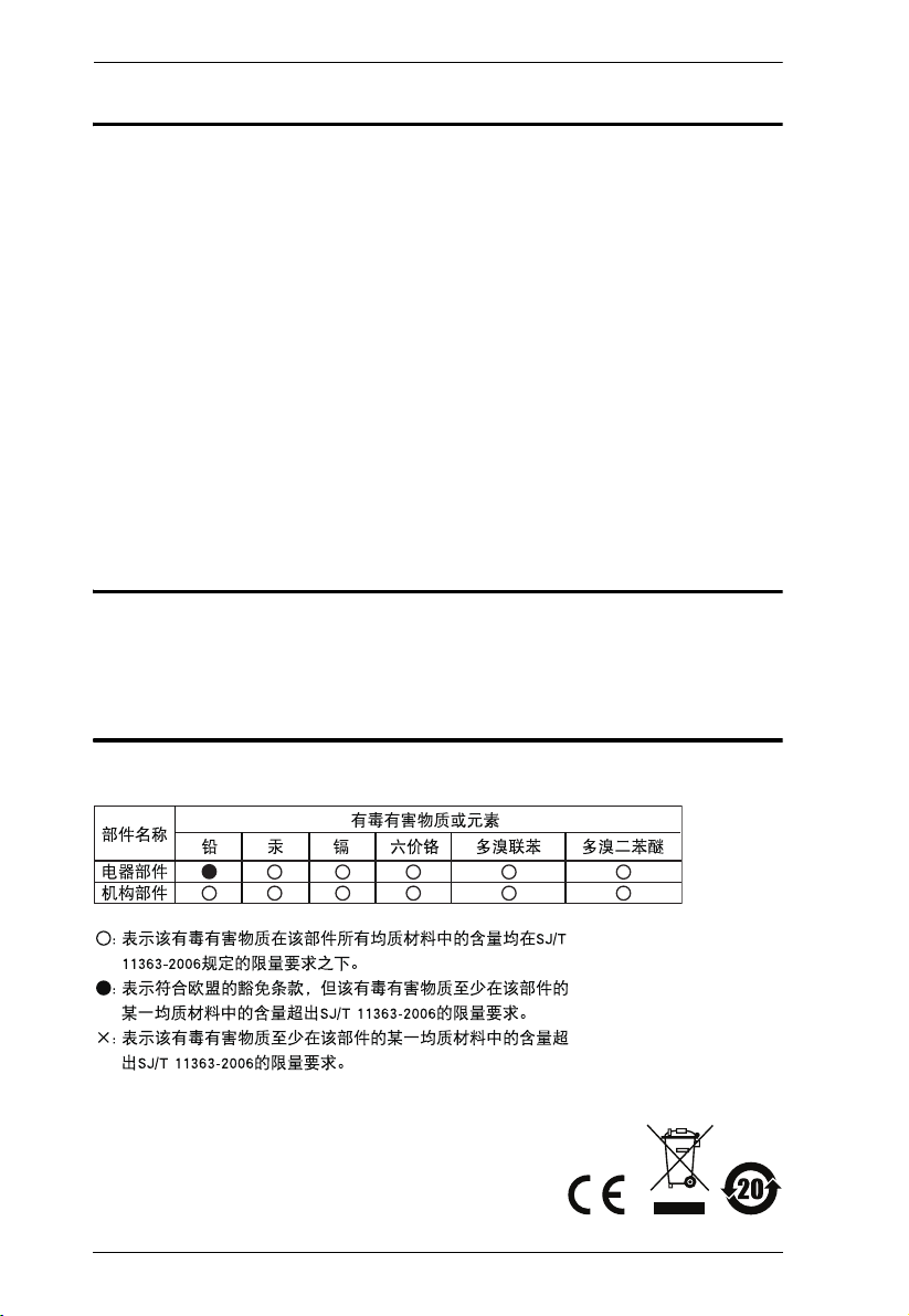
RoHS
This product is RoHS compliant.
SJ/T 11364-2006
The following contains information that relates to China.
ii
CE750 User Manual
User Information
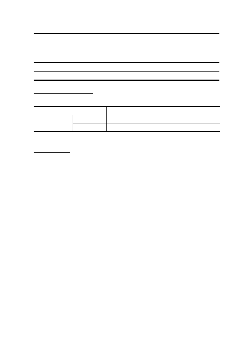
Online Registration
Be sure to register your product at our online support center:
International http://support.aten.com
North America http://www.aten-usa.com/product_registration
Telephone Support
For telephone support, call this number:
International 886-2-8692-6959
North America ATEN TECH 1-888-999-ATEN
ATEN NJ 1-732-356-1703
User Notice
All information, documentation, and specifications contained in this manual
are subject to change without prior notification by the manufacturer. The
manufacturer makes no representations or warranties, either expressed or
implied, with respect to the contents hereof and specifically disclaims any
warranties as to merchantability or fitness for any particular purpose. Any of
the manufacturer's software described in this manual is sold or licensed as is.
Should the programs prove defective following their purchase, the buyer (and
not the manufacturer, its distributor, or its dealer), assumes the entire cost of
all necessary servicing, repair and any incidental or consequential damages
resulting from any defect in the software.
The manufacturer of this system is not responsible for any radio and/or TV
interference caused by unauthorized modifications to this device. It is the
responsibility of the user to correct such interference.
The manufacturer is not responsible for any damage incurred in the operation
of this system if the correct operational voltage setting was not selected prior
to operation. PLEASE VERIFY THAT THE VOLTAGE SETTING IS
CORRECT BEFORE USE.
This ATEN product is specifically designed and manufactured for the
operation and management of computer mainframe and communications
equipment used in network management centers. As such, it may not be
completely appropriate for those environments and sites where special
standards for performance and high reliability are required – such as military
equipment, traffic management, nuclear facilities, security systems,
communications equipment, medical facilities, etc.
iii

CE750 User Manual
© Copyright 2008–2009 ATEN® International Co., Ltd.
Manual Part No. PAPE-0297-AT2G
Manual Date: 2009-04-24
ATEN and the ATEN logo are registered trademarks of ATEN International Co., Ltd. All rights reserved.
All other brand names and trademarks are the registered property of their respective owners.
Package Contents
The CE750 package consists of:
1 CE750L USB KVM Extender (Local Unit)
1 CE750R USB KVM Extender (Remote Unit)
1 USB KVM Cable (1.8 m)
2 Power Adapters
1 Rack Mount Kit
2 Grounding Wires
1 User Manual*
1 Quick Start Guide
Check to make sure that all the components are present and that nothing got
damaged in shipping. If you encounter a problem, contact your dealer.
Read this manual thoroughly and follow the installation and operation
procedures carefully to prevent any damage to the unit, and/or any of the
devices connected to it.
* Features may have been added to the CE750 since this manual was printed.
Please visit our website to download the most up-to-date version of the
manual.
iv

CE750 User Manual
Contents
FCC Information . . . . . . . . . . . . . . . . . . . . . . . . . . . . . . . . . . . . . . . . . . . . . ii
RoHS. . . . . . . . . . . . . . . . . . . . . . . . . . . . . . . . . . . . . . . . . . . . . . . . . . . . . . ii
SJ/T 11364-2006. . . . . . . . . . . . . . . . . . . . . . . . . . . . . . . . . . . . . . . . . . . . . ii
User Information . . . . . . . . . . . . . . . . . . . . . . . . . . . . . . . . . . . . . . . . . . . . .iii
Online Registration . . . . . . . . . . . . . . . . . . . . . . . . . . . . . . . . . . . . . . . .iii
Telephone Support . . . . . . . . . . . . . . . . . . . . . . . . . . . . . . . . . . . . . . . .iii
User Notice . . . . . . . . . . . . . . . . . . . . . . . . . . . . . . . . . . . . . . . . . . . . . .iii
Package Contents. . . . . . . . . . . . . . . . . . . . . . . . . . . . . . . . . . . . . . . . . . . iv
About this Manual . . . . . . . . . . . . . . . . . . . . . . . . . . . . . . . . . . . . . . . . . . . vii
Conventions . . . . . . . . . . . . . . . . . . . . . . . . . . . . . . . . . . . . . . . . . . . . . . . vii
Product Information. . . . . . . . . . . . . . . . . . . . . . . . . . . . . . . . . . . . . . . . . .viii
1. Introduction
Overview . . . . . . . . . . . . . . . . . . . . . . . . . . . . . . . . . . . . . . . . . . . . . . . . . . .1
Features . . . . . . . . . . . . . . . . . . . . . . . . . . . . . . . . . . . . . . . . . . . . . . . . . . .2
Requirements . . . . . . . . . . . . . . . . . . . . . . . . . . . . . . . . . . . . . . . . . . . . . . . 3
Consoles . . . . . . . . . . . . . . . . . . . . . . . . . . . . . . . . . . . . . . . . . . . . . . . . 3
Computers. . . . . . . . . . . . . . . . . . . . . . . . . . . . . . . . . . . . . . . . . . . . . . .3
Cables . . . . . . . . . . . . . . . . . . . . . . . . . . . . . . . . . . . . . . . . . . . . . . . . . .3
Operating Systems . . . . . . . . . . . . . . . . . . . . . . . . . . . . . . . . . . . . . . . . 4
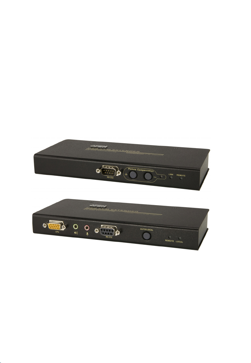
Components . . . . . . . . . . . . . . . . . . . . . . . . . . . . . . . . . . . . . . . . . . . . . . . . 5
CE750L (Local Unit) Front View . . . . . . . . . . . . . . . . . . . . . . . . . . . . . .5
CE750R (Remote Unit) Front View . . . . . . . . . . . . . . . . . . . . . . . . . . . .6
CE750L / CE750R Rear View . . . . . . . . . . . . . . . . . . . . . . . . . . . . . . . .7
Side View . . . . . . . . . . . . . . . . . . . . . . . . . . . . . . . . . . . . . . . . . . . . . . . 7
2. Hardware Setup
Rack Mounting . . . . . . . . . . . . . . . . . . . . . . . . . . . . . . . . . . . . . . . . . . . . . . 9
Installation. . . . . . . . . . . . . . . . . . . . . . . . . . . . . . . . . . . . . . . . . . . . . . . . .11
Grounding . . . . . . . . . . . . . . . . . . . . . . . . . . . . . . . . . . . . . . . . . . . . . .11
Setting Up . . . . . . . . . . . . . . . . . . . . . . . . . . . . . . . . . . . . . . . . . . . . . . 13
Installation Diagrams. . . . . . . . . . . . . . . . . . . . . . . . . . . . . . . . . . . . . .14
CE750L / CE750R Rear View . . . . . . . . . . . . . . . . . . . . . . . . . . . . 14
CE750L Front View . . . . . . . . . . . . . . . . . . . . . . . . . . . . . . . . . . . . 15
3. Operation
Operating Modes. . . . . . . . . . . . . . . . . . . . . . . . . . . . . . . . . . . . . . . . . . . .17
Mode Selection . . . . . . . . . . . . . . . . . . . . . . . . . . . . . . . . . . . . . . . . . . . . .17
Picture Compensation. . . . . . . . . . . . . . . . . . . . . . . . . . . . . . . . . . . . . . . .18
LED Display . . . . . . . . . . . . . . . . . . . . . . . . . . . . . . . . . . . . . . . . . . . . . . .19
CE750L (Local Unit) . . . . . . . . . . . . . . . . . . . . . . . . . . . . . . . . . . . . . .19
CE750R (Remote Unit) . . . . . . . . . . . . . . . . . . . . . . . . . . . . . . . . . . . . 19
Safety Instructions. . . . . . . . . . . . . . . . . . . . . . . . . . . . . . . . . . . . . . . . . . .21
General . . . . . . . . . . . . . . . . . . . . . . . . . . . . . . . . . . . . . . . . . . . . . . . .21
Rack Mounting . . . . . . . . . . . . . . . . . . . . . . . . . . . . . . . . . . . . . . . . . .23
v

CE750 User Manual
Technical Support. . . . . . . . . . . . . . . . . . . . . . . . . . . . . . . . . . . . . . . . . . . 24
International . . . . . . . . . . . . . . . . . . . . . . . . . . . . . . . . . . . . . . . . . . . . 24
North America . . . . . . . . . . . . . . . . . . . . . . . . . . . . . . . . . . . . . . . . . . . 24
Specifications . . . . . . . . . . . . . . . . . . . . . . . . . . . . . . . . . . . . . . . . . . . . . . 25
Troubleshooting . . . . . . . . . . . . . . . . . . . . . . . . . . . . . . . . . . . . . . . . . . . . 26
Overview . . . . . . . . . . . . . . . . . . . . . . . . . . . . . . . . . . . . . . . . . . . . . . . 26
About SPHD Connectors . . . . . . . . . . . . . . . . . . . . . . . . . . . . . . . . . . . . . 26
Limited Warranty. . . . . . . . . . . . . . . . . . . . . . . . . . . . . . . . . . . . . . . . . . . . 26
vi

CE750 User Manual
About this Manual
This User Manual is provided to help you get the most from your system. It
covers all aspects of installation, configuration and operation. An overview of
the information found in the manual is provided below.
Chapter 1, Introduction, introduces you to the CE750 system. Its purpose,
features and benefits are presented, and its front and back panel components
are described.
Chapter 2, Hardware Setup, describes the steps that are necessary to
quickly and safely set up your installation.
Chapter 3, Operation, explains the fundamental concepts involved in
operating the CE750.
An Appendix, provides specifications and other technical information
regarding the CE750.
Conventions
This manual uses the following conventions:
Monospaced Indicates text that you should key in.
[ ] Indicates keys you should press. For example, [Enter] means to
press the Enter key. If keys need to be chorded, they appear
together in the same bracket with a plus sign between them:
[Ctrl+Alt].
1. Numbered lists represent procedures with sequential steps.
♦ Bullet lists provide information, but do not involve sequential steps.
→ Indicates selecting the option (on a menu or dialog box, for
example), that comes next. For example, Start
open the Start menu, and then select Run.
Indicates critical information.
→ Run means to
vii

CE750 User Manual
Product Information
For information about all ATEN products and how they can help you connect
without limits, visit ATEN on the Web or contact an ATEN Authorized
Reseller. Visit ATEN on the Web for a list of locations and telephone numbers:
International http://www.aten.com
North America ATEN TECH http://www.aten-usa.com
ATEN NJ http://www.aten.com
viii

Chapter 1
Introduction
Overview
The CE750 is a USB (Universal Serial Bus) based KVM Extender with
automatic signal compensation and RS-232 serial functionality that allows
access to a computer system from a remote USB console (USB keyboard,
monitor, and USB mouse).
Because it allows access to a computer system from a remote console, the
CE750 is perfect for use in any type of installation where you need to place the
console where it is conveniently accessible, but you want the system equipment
to reside in a safe location – away from the dust and dirt of the factory floor, or
the harsh environmental influence of a construction site, for example.
The CE750 is also useful for control and security purposes, where you can have
the system unit in a secure area at the same time that you put the console in the
most convenient location for user access. This is ideal for managing highly
confidential data systems.
The CE750 improves on previous designs by: 1) the addition of an RS-232
port, on both the Local and Remote Units – the RS-232 port on the Local Unit
allows you to connect to a serial terminal for configuration, while the RS-232
port on the Remote Unit allows you to connect serial devices such as
touchscreens and barcode scanners; 2) the addition of a dedicated KVM port
section on the Local Unit so you can simply and easily include a KVM switch
in your installation; 3) using inexpensive Cat 5e cable instead of bulkier, more
expensive, standard cables, for a much neater, more convenient, more reliable
data transfer connection; 4) its ability to sense the distance to the system and
automatically adjust the gain accordingly; and 5) featuring a custom ASIC to
ensure the utmost in reliability and compatibility.
Further CE750 key features are built-in 8KV/15KV ESD protection and 2KV
surge protection, and picture compensation pushbuttons on the Remote Unit to
adjust the picture on the remote console.
Setup is as easy as can be – simply connect the computer system box and local
console to the Local CE750L Unit; run the Cat 5e cable to the Remote CE750R
Unit (up to 150 meters away); and plug the remote console into the Remote
Module.
1

CE750 User Manual
Features
Local and Remote Units connect at distances up to 150 m using Cat 5e
cable.
Dual console operation – control your system from both the local and
remote USB keyboard, monitor, and mouse consoles
Built-in ASIC for greater reliability and compatibility
Auto Signal Compensation (ASC)
USB Keyboard and USB Mouse Ports
RS-232 serial ports – allows you to connect to a serial terminal for
configuration (Local Unit), or serial devices such as touchscreens and
barcode scanners (Remote Unit)
Supports stereo speakers and stereo microphone
USB overcurrent detection and prevention
Pushbutton operating mode selection (Local Unit only) – select between
Local and Auto operating modes.
Built-in 8KV/15KV ESD protection (Contact voltage 8KV; Air voltage
15KV) and 2KV surge protection
Adjustable gain control – manually adjusts signal strength to compensate
for distance
High resolution video – up to 1920 x 1200@60Hz (30 m ); 1600 x
1200@60Hz (150 m); 1280 x 1024@60Hz (200 m)
Supports VGA, SVGA, SXGA (1280 x 1024) and UXGA (1600 x 1200)
and multisync monitors; local monitor supports DDC; DDC2; DDC2B
Hot pluggable
Rack mountable
Easy to install – no software required – connecting cables to the devices is
all it takes
2

Chapter 1. Introduction
Requirements
Consoles
A VGA, SVGA, SXGA, UXGA, or multisync monitor capable of the
highest resolution that you will be using on any computer in the
installation
Note: If you connect a DDC type monitor to the Local Unit, the monitor
that connects to the Remote Unit must be able to support the highest
video resolution that the DDC monitor can provide
A USB keyboard
Note: You can use different brands and models of USB keyboard on the
Local and Remote Units, but support for multi-function keyboards
is limited to the standard 104 keys.
A USB mouse
Note: You can use different brands and models of mouse on the Local and
Remote Units, but only the left and right mouse buttons and scroll
wheel features are supported. Other mouse features are not
supported.
Computers
The following equipment must be installed on each computer that is to be
connected to the system:
A VGA, SVGA, SXGA, UXGA, or multisync card.
USB host controller and Type A USB port.
Cables
For optimal signal integrity, and to simplify the layout, we strongly
recommend that you use the high quality custom USB KVM Cable that is
provided with this package.
Cat 5e cable is the minimum required to connect the Local and Remote
CE750 Units. Cable of a lower standard will result in degrading of the
video signal. For best performance, we strongly recommend Cat 5e cable.
3
 Loading...