

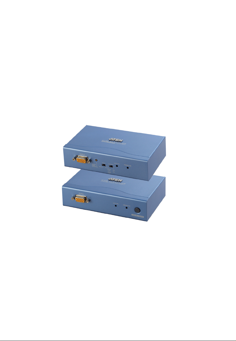
KVM Extender
CE252
User Manual
www.aten.com
CE252 User Manual
FCC Information
This is an FCC Class A product. In a domestic environment this product may
cause radio interference in which case the user may be required to take
adequate measures.
This equipment has been tested and found to comply with the limits for a Class
A digital device, pursuant to Part 15 of the FCC Rules. These limits are
designed to provide reasonable protection against harmful interference when
the equipment is operated in a commercial environment. This equipment
generates, uses and can radiate radio frequency energy and, if not installed and
used in accordance with the instruction manual, may cause harmful
interference to radio communications. Operation of this equipment in a
residential area is likely to cause harmful interference in which case the user
will be required to correct the interference at his own expense.
RoHS
This product is RoHS compliant.
SJ/T 11364-2006
The following contains information that relates to China.
ii

CE252 User Manual
User Information
Online Registration
Be sure to register your product at our online support center:
International http://support.aten.com
North America ATEN TECH http://www.aten-usa.com/product_registration
ATEN NJ http://support.aten.com
Telephone Support
For telephone support, call this number:
International 886-2-8692-6959
North America ATEN TECH 1-888-999-ATEN
ATEN NJ 1-732-356-1703
User Notice
All information, documentation, and specifications contained in this manual
are subject to change without prior notification by the manufacturer. The
manufacturer makes no representations or warranties, either expressed or
implied, with respect to the contents hereof and specifically disclaims any
warranties as to merchantability or fitness for any particular purpose. Any of
the manufacturer's software described in this manual is sold or licensed as is.
Should the programs prove defective following their purchase, the buyer (and
not the manufacturer, its distributor, or its dealer), assumes the entire cost of
all necessary servicing, repair and any incidental or consequential damages
resulting from any defect in the software.
The manufacturer of this system is not responsible for any radio and/or TV
interference caused by unauthorized modifications to this device. It is the
responsibility of the user to correct such interference.
The manufacturer is not responsible for any damage incurred in the operation
of this system if the correct operational voltage setting was not selected prior
to operation. PLEASE VERIFY THAT THE VOLTAGE SETTING IS
CORRECT BEFORE USE.
This ATEN product is specifically designed and manufactured for the
operation and management of computer mainframe and communications
equipment used in network management centers. As such, it may not be
completely appropriate for those environments and sites where special
standards for performance and high reliability are required – such as military
equipment, traffic management, nuclear facilities, security systems,
communications equipment, medical facilities, etc.
iii

CE252 User Manual
A
Package Contents
The CE252 KVM Extender package consists of:
1 CE252L KVM Extender (Local Unit)
1 CE252R KVM Extender (Remote Unit)
2 Custom KVM Cables
1 Power Adapter
2 Rack Mount Kits
2 Grounding Wires
1 User Manual*
1 Quick Start Guide
Check to make sure that all the components are present and that nothing got
damaged in shipping. If you encounter a problem, contact your dealer.
Read this manual thoroughly and follow the installation and operation
procedures carefully to prevent any damage to the unit, and/or any of the
devices connected to it.
* Features may have been added to the CE252 since this manual was printed.
Please visit our website to download the most up-to-date version of the
manual.
© Copyright 2008 ATEN® International Co., Ltd.
Manual Part No. PAPE-0277-200G
Manual Date: 2008-07-16
TEN and the ATEN logo are registered trademarks of ATEN International Co., Ltd. All rights reserved.
All other brand names and trademarks are the registered property of their respective owners.
iv

CE252 User Manual
Contents
FCC Information . . . . . . . . . . . . . . . . . . . . . . . . . . . . . . . . . . . . . . . . . . . . . ii
RoHS. . . . . . . . . . . . . . . . . . . . . . . . . . . . . . . . . . . . . . . . . . . . . . . . . . . . . . ii
SJ/T 11364-2006. . . . . . . . . . . . . . . . . . . . . . . . . . . . . . . . . . . . . . . . . . . . . ii
User Information . . . . . . . . . . . . . . . . . . . . . . . . . . . . . . . . . . . . . . . . . . . . .iii
Online Registration . . . . . . . . . . . . . . . . . . . . . . . . . . . . . . . . . . . . . . . .iii
Telephone Support . . . . . . . . . . . . . . . . . . . . . . . . . . . . . . . . . . . . . . . .iii
User Notice . . . . . . . . . . . . . . . . . . . . . . . . . . . . . . . . . . . . . . . . . . . . . .iii
Package Contents. . . . . . . . . . . . . . . . . . . . . . . . . . . . . . . . . . . . . . . . . . . iv
About this Manual . . . . . . . . . . . . . . . . . . . . . . . . . . . . . . . . . . . . . . . . . . . vii
Conventions . . . . . . . . . . . . . . . . . . . . . . . . . . . . . . . . . . . . . . . . . . . . . . . vii
Product Information. . . . . . . . . . . . . . . . . . . . . . . . . . . . . . . . . . . . . . . . . .viii
1. Introduction
Overview . . . . . . . . . . . . . . . . . . . . . . . . . . . . . . . . . . . . . . . . . . . . . . . . . . .1
Features . . . . . . . . . . . . . . . . . . . . . . . . . . . . . . . . . . . . . . . . . . . . . . . . . . .2
Requirements . . . . . . . . . . . . . . . . . . . . . . . . . . . . . . . . . . . . . . . . . . . . . . . 3
Console . . . . . . . . . . . . . . . . . . . . . . . . . . . . . . . . . . . . . . . . . . . . . . . . .3
Computers. . . . . . . . . . . . . . . . . . . . . . . . . . . . . . . . . . . . . . . . . . . . . . .3
Cables . . . . . . . . . . . . . . . . . . . . . . . . . . . . . . . . . . . . . . . . . . . . . . . . . .3
Components . . . . . . . . . . . . . . . . . . . . . . . . . . . . . . . . . . . . . . . . . . . . . . . . 4
CE252L Front View . . . . . . . . . . . . . . . . . . . . . . . . . . . . . . . . . . . . . . . . 4
CE252R Front View. . . . . . . . . . . . . . . . . . . . . . . . . . . . . . . . . . . . . . . .5
CE252L / CE252R Rear View . . . . . . . . . . . . . . . . . . . . . . . . . . . . . . . .6
2. Hardware Setup
Rack Mounting . . . . . . . . . . . . . . . . . . . . . . . . . . . . . . . . . . . . . . . . . . . . . . 7
Installation. . . . . . . . . . . . . . . . . . . . . . . . . . . . . . . . . . . . . . . . . . . . . . . . . .9
Grounding . . . . . . . . . . . . . . . . . . . . . . . . . . . . . . . . . . . . . . . . . . . . . . .9
Setting Up . . . . . . . . . . . . . . . . . . . . . . . . . . . . . . . . . . . . . . . . . . . . . . 11
Installation Diagram. . . . . . . . . . . . . . . . . . . . . . . . . . . . . . . . . . . . . . .12
3. Operation
Access Methods . . . . . . . . . . . . . . . . . . . . . . . . . . . . . . . . . . . . . . . . . . . .13
Hotkey Operation . . . . . . . . . . . . . . . . . . . . . . . . . . . . . . . . . . . . . . . .13
Auto Scan Mode (ASM). . . . . . . . . . . . . . . . . . . . . . . . . . . . . . . . . . . .14
[Left Shift] [Right Shift]. . . . . . . . . . . . . . . . . . . . . . . . . . . . . . . . . .14
Changing the Scan Interval . . . . . . . . . . . . . . . . . . . . . . . . . . . . . . . . .14
[Left shift] [Right shift] [n] . . . . . . . . . . . . . . . . . . . . . . . . . . . . . . . .14
Using Gain Controls . . . . . . . . . . . . . . . . . . . . . . . . . . . . . . . . . . . . . . 15
Accessing Local Computers . . . . . . . . . . . . . . . . . . . . . . . . . . . . . . . .15
LED Display . . . . . . . . . . . . . . . . . . . . . . . . . . . . . . . . . . . . . . . . . . . . . . .16
CE252L (Local Unit) . . . . . . . . . . . . . . . . . . . . . . . . . . . . . . . . . . . . . .16
CE252R (Remote Unit) . . . . . . . . . . . . . . . . . . . . . . . . . . . . . . . . . . . . 16
v

CE252 User Manual
Appendix
Safety Instructions . . . . . . . . . . . . . . . . . . . . . . . . . . . . . . . . . . . . . . . . . . 17
General . . . . . . . . . . . . . . . . . . . . . . . . . . . . . . . . . . . . . . . . . . . . . . . . 17
Rack Mounting . . . . . . . . . . . . . . . . . . . . . . . . . . . . . . . . . . . . . . . . . . 19
Technical Support. . . . . . . . . . . . . . . . . . . . . . . . . . . . . . . . . . . . . . . . . . . 20
International . . . . . . . . . . . . . . . . . . . . . . . . . . . . . . . . . . . . . . . . . . . . 20
North America . . . . . . . . . . . . . . . . . . . . . . . . . . . . . . . . . . . . . . . . . . . 20
Specifications . . . . . . . . . . . . . . . . . . . . . . . . . . . . . . . . . . . . . . . . . . . . . . 21
VGA Pin Assignments . . . . . . . . . . . . . . . . . . . . . . . . . . . . . . . . . . . . . . . 22
TP Wiring Diagram . . . . . . . . . . . . . . . . . . . . . . . . . . . . . . . . . . . . . . . . . . 22
TP Pin Assignments . . . . . . . . . . . . . . . . . . . . . . . . . . . . . . . . . . . . . . . . . 22
Troubleshooting . . . . . . . . . . . . . . . . . . . . . . . . . . . . . . . . . . . . . . . . . . . . 23
About SPHD Connectors . . . . . . . . . . . . . . . . . . . . . . . . . . . . . . . . . . . . . 24
Limited Warranty. . . . . . . . . . . . . . . . . . . . . . . . . . . . . . . . . . . . . . . . . . . . 24
vi

CE252 User Manual
About this Manual
This User Manual is provided to help you get the most from your c/c system.
It covers all aspects of installation, configuration and operation. An overview
of the information found in the manual is provided below.
Chapter 1, Introduction, introduces you to the CE252 system. Its purpose,
features and benefits are presented, and its front and back panel components
are described.
Chapter 2, Hardware Setup, describes how to set up your installation. The
necessary steps – from a basic single stage hookup to a complete 32 switch
daisy chained operation are provided.
Chapter 3, Operation, explains the fundamental concepts involved in
operating the CE252.
An Appendix, provides specifications and other technical information
regarding the CE252.
Conventions
This manual uses the following conventions:
Monospaced Indicates text that you should key in.
[ ] Indicates keys you should press. For example, [Enter] means to
press the Enter key. If keys need to be chorded, they appear
together in the same bracket with a plus sign between them:
[Ctrl+Alt].
1. Numbered lists represent procedures with sequential steps.
♦ Bullet lists provide information, but do not involve sequential steps.
→ Indicates selecting the option (on a menu or dialog box, for
example), that comes next. For example, Start
open the Start menu, and then select Run.
Indicates critical information.
→ Run means to
vii

CE252 User Manual
Product Information
For information about all ATEN products and how they can help you connect
without limits, visit ATEN on the Web or contact an ATEN Authorized
Reseller. Visit ATEN on the Web for a list of locations and telephone numbers:
International http://www.aten.com
North America ATEN TECH http://www.aten-usa.com
ATEN NJ http://www.aten.com
viii

Chapter 1
Introduction
Overview
The CE252 offers local and remote access to your KVM installation. Both (local
and remote) KVM extenders support PS/2 consoles and can be located up to
300 m (1000 feet) apart.
You can reliably manage a large number of computers via a KVM switch.
Additional computers can also be connected to the remote KVM extender.
The CE252 also features Automatic Gain Control, which compensates signal
strength as the distance between the local and remote KVM extenders varies
(over Cat 5 cables). This translates into high resolution video at a lower cost.
The CE252 uses a custom ASIC to ensure the utmost reliability and
compatibility. This technology comprises automatic distance sensing and signal
strength (gain) adjustment.
Setup is easy – simply connect the computer system box (or KVM switch) and
Local Console to the CE252 Local Unit; run a Cat. 5 cable to the CE252 Remote
Unit (up to 300 meters away); finally plug the Remote Console into the Remote
Unit.
1

CE252 User Manual
Features
Local and Remote units connect at distances up to 300m using Cat. 5 cable
Dual Console Operation – control the system from both the local and remote
consoles
Remote unit allows additional PC connection
Built-in ASIC for greater reliability and compatibility
PS/2 and Microsoft Intellimouse supported
Pushbutton selection – sequential selection between local and auto mode
Hotkey operation – switching between PCs
High resolution video – up to 1600 x 1200 @ 60Hz
VGA, SVGA, and multisync monitor support
Local monitor supports DDC2B
Two gain control modes provided to compensate for distance for the
sharpest video quality:
Adjustable gain control – manually adjusts signal strength
Automatic gain control – automatically adjusts signal strength
Built-in 8KV ESD protection and 2KV surge protection
Local unit takes its power from the computer – external power is only
required when the power from the local computer/computers in the KVM
installation is insufficient*
Easy to install – no software required – connecting cables to the devices is
all it takes
Note: If you choose to purchase a power adapter for use with the CE252L, be
sure to get one with the same specifications as the one provided in this
package for the CE252R
2
 Loading...