

© Copyright 2012 ATEN® International Co., Ltd.
ATEN and the ATEN logo are trademarks of ATEN International Co., Ltd. All rights reserved. All other
trademarks are the property of their respective owners.
This product is RoHS compliant.
Part No. PAPE-1285-321G Printing Date: 03/2012
CE100 Mini USB KVM Extender User Guide
Guide d’utilisation du système d’extension KVM USB mini CE100
CE100 Mini-USB-KVM-Verlängerung Benutzerhandbuch
CE100 Alargador KVM de tipo USB mini Manual del usuario
Requirements
Consoles
• A VGA, SVGA, XGA, SXGA, UXGA, WUXGA, or Multisync monitor
capable of the highest resolution that you will be using on the installation
• A USB keyboard
• A USB mouse
Computers
The following equipment must be installed on each computer that is to be
connected to the system:
• A VGA, SVGA, XGA, SXGA, UXGA, WUXGA, or Multisync card
• USB Host Controller and Type A USB Port
Cables
• Use the USB /VGA Cable to connect the components on your installation.
• Cat 5e cable is the minimum required to connect the local and remote
CE100 units. Cable of a lesser standard will result in degrading the video
signal. For best performance, we strongly recommend Cat 5e cable.
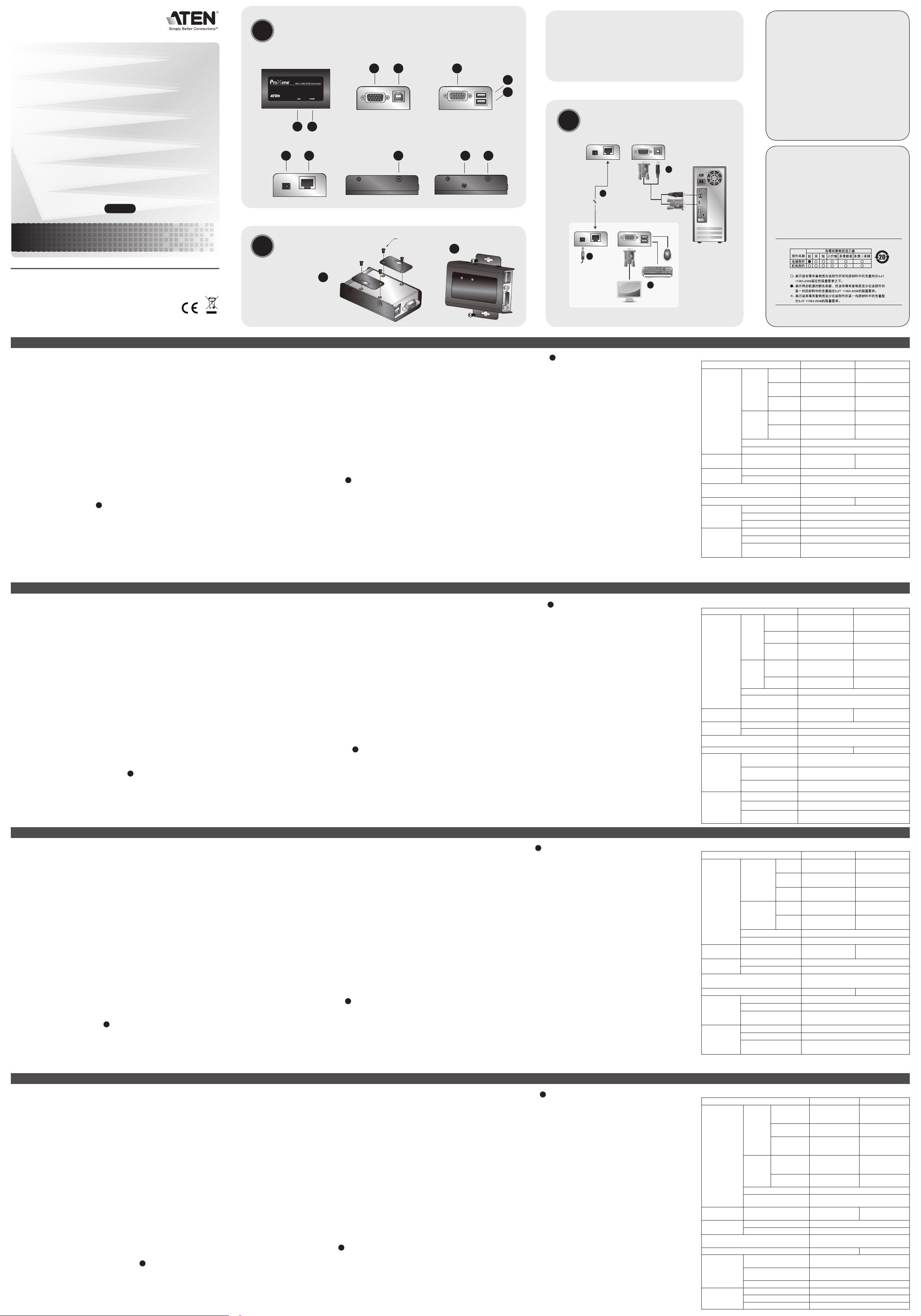
Hardware Review A
CE100L / CE100R Top View
1. Power LED
2. Link LED
CE100L Front View
1. VGA In Port
2. USB Type B port
Voraussetzungen
Konsolen
• Ein VGA-, SVGA-, XGA-, SXGA-, UXGA-, WUXGA- oder MultisyncMonitor, der in der Lage ist, die höchste Aufl ösung darzustellen, die Sie
auf einem der zu installierenden Geräte verwenden möchten.
• Eine USB-Tastatur
• Eine USB-Maus
Computer
Auf den Computern, die mit dem System verbunden werden sollen, muss
mindestens Folgendes installiert sein:
• Eine VGA-, SVGA-, XGA-, SXGA-, UXGA-, WUXGA- oder MultisyncGrafi kkarte
• USB-Host-Controller und USB-Anschluss Typ A
Kabel
• Verbinden Sie die anzuschließenden Komponenten über das USB-/VGAKabel
• Zur Verbindung der lokalen und entfernten CE100-Geräte wird mindestens
ein Kat.-5e-Kabel benötigt. Kabel geringerer Standards führen zu
schlechterer Bildqualität. Um optimale Ergebnisse zu erzielen, empfehlen
wir die Verwendung von Kat-5e-Kabeln.
Hardwareübersicht A
Oberseite des CE100L / CE100R
1. LED-Betriebsanzeige
2. Verbindungsanzeige
Requisitos
Consolas
• Un monitor VGA, SVGA, XGA, SXGA, UXGA, WUXGA o MultiSync
capaz de representar la resolución más elevada que vaya a usar en la
instalación.
• Un teclado USB
• Un mouse USB
PCs
En cada computadora que vaya a conectar al sistema se tienen que instalar
los siguientes componentes:
• Una tarjeta gráfi ca VGA, SVGA, XGA, SXGA, UXGA, WUXGA o multisync
• Una controladora USB y un puerto USB de tipo A
Cables
• Utilice el cable USB/VGA para conectar los componentes que desee
instalar.
• Se requiere como mínimo un cable de Cat. 5e para conectar la consola
local y la unidad remota CE100. Un cable de calidad inferior tiende a
deteriorar la señal gráfi ca. Para mejores resultados, le recomendamos
vivamente que emplee un cable de Cat. 5e.
Presentación del hardware A
CE100L / CE100R – Vista superior
1. Indicador LED de alimentación
2. Indicador de enlace (Link)
Confi guration minimale
Consoles
• Moniteur VGA, SVGA, XGA, SXGA, UXGA, WUXGA ou Multisync prenant
en charge la plus haute résolution utilisée sur l’installation
• Un clavier USB
• Une souris USB
Ordinateurs
Les composants suivants doivent être installés sur chaque ordinateur à
connecter au système :
• Une carte VGA, SVGA, XGA, SXGA, UXGA, WUXGA ou Multisync
• Un contrôleur d'hôte USB et un port USB de type A
Câbles
• Utilisez le câble USB/VGA pour connecter les composants à votre
installation.
• La connexion entre la console locale et la console distante du système
CE100 requiert au minimum un câble de catégorie 5e. Un câble de
catégorie inférieure tend à dégrader les signaux vidéo. Pour des résultats
optimaux, nous vous recommandons fortement d'utiliser un câble de
catégorie 5e.
Description de l’appareil A
Vue supérieure du CE100L/CE100R
1. Voyant d’alimentation
2. Voyant de liaison (Link)
Vue avant du CE100L
CE100R Front View
1. VGA Out Port
2. Mouse Port
3. Keyboard Port
CE100L/CE100R Rear View
1. Power Jack
2. Remote I/O
CE100L Side View
1. Grounding Terminal
CE100R Side View
1. Video Compensation Tuner
2. Grounding Terminal
Hardware Installation B
Mounting
For convenience and fl exibility, the CE100L and CE100R can be wall
mounted or mounted on system racks, as follows:
1. Using the screws provided in the Rack Mount Kit, screw the mounting
brackets into the bottom unit as shown in the diagram.
2. Screw the brackets into any convenient location on the wall or rack. (These
screws are not included.)
Vorderseitige Ansicht des CE100L
1. VGA-Eingang
2. USB-Anschluss, Typ B
Vorderseitige Ansicht des CE100R
1. VGA-Ausgang
2. Mausanschluss
3. Tastaturanschluss
Rückseite des CE100L / CE100R
1. Stromeingangsbuchse
2. E/A zur Gegenstelle
Seitliche Ansicht des CE100L
1. Erdungsanschluss
Seitliche Ansicht des CE100R
1. Bildsignalkompensationsregler
2. Erdungsanschluss
Hardware installieren B
Montage
Um mehr Flexibilität und Komfort zu bieten, kann der CE100L bzw. CE100R
an die Wand aufgehängt oder im Rack eingebaut werden. Dies geschieht
wie folgt:
1. Verwenden Sie die mitgelieferten Schrauben, um die Montagerahmen auf
die Unterseite des Gerätes zu schrauben (siehe das Diagramm).
2. Schrauben Sie die Rahmen an einen geeigneten Ort an der Wand fest.
(Die Schrauben hierfür sind nicht im Lieferumfang enthalten.)
CE100L – Vista frontal
1. Puerto de entrada VGA
2. Puerto USB de tipo B
CE100R – Vista frontal
1. Salida VGA
2. Puerto de mouse
3. Puerto de teclado
CE100L / CE100R – Vista posterior
1. Entrada de alimentación
2. Puerto E/S para equipo remoto
CE100L - Vista lateral
1. Toma de tierra
CE100R - Vista lateral
1. Ajuste de compensación de señal gráfi ca
2. Toma de tierra
Instalar el hardware B
Montaje
Para un mayor confort y más fl exibilidad, el CE100L y el CE100R pueden
montarse en la pared o en un rack.
1. Atornille como se indica en el siguiente diagrama los marcos de montaje
en la parte inferior de la unidad con los tornillos incluidos.
2. Atornille los marcos en una posición deseada en la pared o del rack. (Los
tornillos necesarios no vienen incluidos con la unidad.)
1. Port d'entrée VGA
2. Port USB de type B
Vue avant du CE100R
1. Port de sortie VGA
2. Port souris
3. Port clavier
Vue arrière du CE100L/CE100R
1. Prise d’alimentation
2. E/S distantes
Vue latérale du CE100L
1. Prise de terre
Vue latérale du CE100R
1. Réglage de la compensation vidéo
2. Prise de terre
Installation du matériel B
Montage
Pour plus de confort et de fl exibilité, les consoles CE100L et CE100R
peuvent être montées au mur ou sur bâti, de la manière suivante :
1. Vissez les supports de montage sur bâti sur la partie inférieure de
l'appareil à l'aide des vis fournies, comme indiqué sur le schéma.
2. Vissez les supports au mur ou au bâti à n’importe quel endroit vous
semblant adapté. (Les vis ne sont pas fournies.)
Connecting the Cables
C
Setting up the Mini USB KVM Extender system is simply a matter of
plugging in the cables. Refer to the installation diagram (the numbers in the
diagram correspond to the numbers of the steps), as you do the following:
1. Use the USB/VGA cable to connect the CE100L to a USB/VGA port on
the local computer (or KVM switch).
2. Plug the remote keyboard, monitor and mouse into their respective ports
on the CE100R.
3. Use Cat 5e cable to connect the Local Unit’s (CE100L) I/O port with the I/
O port of the Remote Unit (CE100R).
4. Plug the power adapter supplied with this package into an AC source;
plug the adapter's cable into the CE100R's Power Jack.
Note: The CE100L doesn’t require a power adapter, since it gets its
power over the USB/VGA connection.
Operation
• Use the keyboard, monitor, and mouse at the remote location to operate
the computer at the local site.
• Adjust the video quality of the display at the remote location with the Video
Compensation Tuner.
Kabel anschließen
C
Die Installation der Mini-KVM-USB-Verlängerung ist mit ein paar wenigen
Kabelanschlüssen erledigt. Siehe das Installationsdiagramm (die Zahlen im
Diagramm entsprechen der Reihenfolge), und gehen Sie folgendermaßen
vor:
1. Verbinden Sie den CE100L mit einem USB-/VGA-Port am lokalen
Computer (oder KVM-Switch). Verwenden Sie dazu das USB-/VGAKabel.
2. Verbinden Sie Tastatur, Maus und Monitor des Gerätes der Gegenstelle
mit den entsprechenden Ports am CE100R.
3. Verbinden Sie den Anschluss I/O des lokalen Gerätes (CE100L) mit dem
Anschluss I/O des Gerätes der Gegenstelle (CE100R).
4. Verbinden Sie das mitgelieferte Netzteil mit einer Steckdose und sein
Netzkabel mit der Stromeingangsbuchse des Gerätes.
Hinweis: Der CE100L benötigt kein Netzteil, er wird über die USB-/VGA-
Kabelverbindung mit Strom versorgt.
Bedienung
• Verwenden Sie Tastatur, Monitor und Maus der Gegenstelle, um den
lokalen Computer zu bedienen.
• Regeln Sie die Bildqualität auf Seiten der Gegenstelle mit dem
Bildsignalkompensationsregler nach.
Conectar los cables
C
La instalación del sistema alargador KVM de tipo USB Mini es tan sencilla
como conectar unos cables. Véase el diagrama de instalación (los números
en el diagrama equivalen a los números de los pasos a seguir) y proceda
como se indica a continuación:
1. Emplee el cable USB/VGA para conectar el CE100L a un puerto USB/
VGA de la computadora local (o conmutador KVM).
2. Conecte el teclado, el mouse y el monitor remotos a los puertos de
correspondientes del CE100R.
3. Conecte el puerto E/S de la unidad local (CE100L) al puerto E/S de la
unidad remota (CE100R). Para ello, emplee un cable de Cat. 5e.
4. Conecte el adaptador de alimentación incluido a una toma eléctrica, y el
cable del adaptador a la entrada de corriente del CE100R.
Nota: El CE100L no requiere adaptador de alimentación, dado que se
alimenta del cable USB/VGA.
Funcionamiento
• Emplee el teclado, monitor y mouse remotos para controlar la
computadora local.
• Ajuste la calidad de imagen de la pantalla remota con el sintonizador de
compensación de señal.
Connexion des câbles
C
L’installation du système d’extension KVM USB mini se résume à connecter
les câbles. Reportez-vous au schéma de connexion (les numéros du
schéma correspondent aux numéros des étapes ci-dessous) en procédant
comme suit :
1. Utilisez le câble USB/VGA pour connecter le CE100L à un port USB/VGA
sur l’ordinateur local (ou commutateur KVM).
2. Branchez le clavier, le moniteur et la souris distants dans leurs ports
respectifs sur le CE100R.
3. Utilisez un câble de catégorie 5e pour connecter le port d’E/S de l’unité
locale (CE100L) au port d’E/S de l’unité distante (CE100R).
4. Connectez l'adaptateur secteur fourni avec ce package à la source
d'alimentation CA, et le câble de l'adaptateur à la prise jack du CE100R.
Remarque : La console CE100L ne requiert pas d’adaptateur secteur car
elle est alimentée via la connexion USB/VGA.
Fonctionnement
• Utilisez le clavier, le moniteur et la souris à l’emplacement distant pour
faire fonctionner l’ordinateur sur le site local.
• À l’aide du réglage de la compensation vidéo, ajustez la qualité vidéo de
l’écran à l’emplacement distant.
Specifi cations
Function CE100L CE100R
Connectors
Console
Ports
Keyboard N/A
1 x USB Type A
Female (White)
Video N/A
1 x HDB-15 Female
(Blue)
Mouse N/A
1 x USB Type A
Female (White)
KVM
Ports
Keyboard /
Mouse
1 x USB Type B
Female (White)
N/A
Video
1 x HDB-15 Male
(Blue)
N/A
Power 1 x DC Jack
Unit to Unit 1 x RJ-45 Female (Black)
Switch
Video Compensation
Tuner
N/A 1 x Knob
LEDs
Link 1 (Blue)
Power 1 (Green)
Video
1920 x 1200 @ 60 Hz (30m);
1280 x 1024 @ 60 Hz (100m)
Power Consumption DC5V, 0.5W DC5V, 1.25W
Environment
Operating Temp. 0–50ºC
Storage Temp -20–60ºC
Humidity 0–80% RH, Non-condensing
Physical
Properties
Housing Metal
Weight 0.16 kg
Dimensions
(L x W x H)
9.00 x 5.50 x 2.40 cm
Technische Daten
Funktion CE100L CE100R
Anschlüsse
Konsol ports
Tastatur --
1 x USB Typ A
Weiblein (weiß)
Grafi k --
1 x HDB-15 Weiblein
(blau)
Maus --
1 x USB Typ A
Weiblein (weiß)
KVM-Ports
Tastatur/
Maus
1 x USB Typ B
Weiblein (weiß)
--
Grafi k
1 x HDB-15
Männlein (blau)
--
Stromversorgung 1 x Stromeingangsbuchse
Gerät an Gerät 1 x RJ-45 Weiblein (schwarz)
Schalter
Bildsignal kompensationsregler
-- 1 x Drehregler
LEDAnzeigen
Verbindung 1 (blau)
Betrieb 1 (grün)
Grafi k
1920 x 1200 bei 60 Hz (30m);
1280 x 1024 bei 60 Hz (100m)
Stromverbrauch 5 V=, 0,5 W 5 V=, 1,25 W
Umgebung
Betriebstemperatur 0 – 50 ºC
Lagertemperatur -20 – 60 ºC
Feuchtigkeit
0 -80% rel. Luftfeuchte, nicht
kondensierend
Physische
Eigenschaften
Gehäuse Metall
Gewicht 0,16 kg
Abmessungen
(L x B x H)
9,00 x 5,50 x 2,40 cm
Especifi caciones
Función CE100L CE100R
Conectores
Puertos
de
consola
Teclado --
1 conector USB
hembra de tipo A
(blanco)
Señal gráfi ca --
1 conector HDB15 hembra (azul)
Mouse --
1 conector USB
hembra de tipo A
(blanco)
Puertos
KVM
Teclado /
mouse
1 conector USB
hembra de tipo B
(blanco)
--
Señal gráfi ca
1 conector HDB-
15 macho (azul)
--
Alimentación 1 toma de c.c.
Puerto de unidad a
unidad
1 conector RJ-45 hembra (negro)
Interruptor
Ajuste de compensa ción
de señal gráfi ca
-- 1 dial
Indicadores
LED
Enlace 1 (azul)
Alimentación 1 (verde)
Señal gráfi ca
1920 x 1200 a 60 Hz (30 m);
1280 x 1024 a 60 Hz (100 m)
Consumo c.c. 5 V, 0,5 W c.c. 5 V, 1,25 W
Entorno
Temperatura de
funcionamiento
0 a 50 ºC
Temperatura de
almacenamiento
-20 a 60 ºC
Humedad 0 a 80% de HR, sin condensar
Propiedades
físicas
Carcasa Metálica
Peso 0,16 kg
Dimensiones (L x An x Al) 9,00 x 5,50 x 2,40 cm
Caractéristiques techniques
Fonction CE100L CE100R
Connecteurs
Ports de
console
Clavier N/D
1 connecteur USB
femelle de Type A
(blanc)
Vidéo N/D
1 connecteur HDB-15
femelle (bleu)
Souris N/D
1 connecteur USB
femelle de Type A
(blanc)
Ports
KVM
Clavier /
Souris
1 connecteur USB
femelle de Type B
(blanc)
N/D
Vidéo
1 connecteur HDB-15
mâle (bleu)
N/D
Alimentation 1 prise d’alimentation CC
Connexion d'unité à
unité
1 connecteur RJ-45 femelle (noir)
Commutateur
Réglage de la
compensa tion vidéo
N/D 1 bouton
Voyants
Lien 1 voyant (bleu)
Alimentation 1 voyant (vert)
Vidéo
1920 x 1200 @ 60 Hz (30 m) ;
1280 x 1024 @ 60 Hz (100 m)
Consommation électrique 5 Vcc - 0,5 W 5 Vcc - 1,25 W
Environnement
Température de
fonctionnement
0 à 50 ºC
Température de
stockage
-20 à 60 ºC
Humidité
Humidité relative de 0 à 80 %, sans
condensation
Propriétés
physiques
Boîtier Métallique
Poids 0,16 kg
Dimensions (Longueur
x Largeur x Hauteur)
9,00 x 5,50 x 2,40 cm
CE100R/CE100L Top View
CE100L/CE100R Rear View
Connecting the Cables
CE100L Front View
CE100R Side View
CE100R Front View
Mounting
CE100L Side View
Mini USB KVM Extender
CE100
Package Contents
1 CE100L Mini USB KVM Extender (Local Unit)
1 CE100R Mini USB KVM Extender (Remote Unit)
1 USB/VGA Cable
1 Power Adapter (for Remote Unit)
1 Mounting Kit
1 User Instructions
CE100L
3
4
1
2
Cat 5e Cable
(up to 100 m)
CE100R
The following contains information that relates to China:
Online Registration
International:
http://support.aten.com
North America:
http://www.aten-usa.com/product_registration
Technical Phone Support
International:
886-2-86926959
North America:
1-888-999-ATEN Ext: 4988
United Kingdom:
44-8-4481-58923
FCC Information
This equipment has been tested and found to comply with
the limits for a Class A digital device, pursuant to Part 15
of the FCC Rules. These limits are designed to provide
reasonable protection against harmful interference in a
residential installation. This equipment generates, uses
and can radiate radio frequency energy, and if not installed
and used in accordance with the instruction manual, may
cause interference to radio communications. However,
there is no guarantee that interference will not occur in a
particular installation. If this equipment does cause harmful
interference to radio or television reception, which can be
determined by turning the equipment off and on, the user
is encouraged to try to correct the interference by one or
more of the following measures:
• Reorient or relocate the receiving antenna;
• Increase the separation between the equipment and
receiver;
• Connect the equipment into an outlet on a circuit different
from that which the receiver is connected;
• Consult the dealer/an experienced radio/television
technician for help.
All information, documentation, and specifi cations contained
in this media are subject to change without prior notifi cation
by the manufacturer. Please visit our website to fi nd the
most up to date version.
User Guide
www.aten.com
www.aten.com
www.aten.com
www.aten.com
Hardware Review
Hardware Installation
A
B
C
7
1
4
5
3
1
2
3
43
1 2
Philips Head M3 L:5
1
6 7
1 2
2
8 9
1 2
12
12
サポートお問合せ窓口:+81-3-5615-5811
CE
100
ミニUSB KVM
エクステンダー ユーザーガイド
CE100 Mini USB KVM 확장기 사용자 가이드
Hardware
Installation
B C
Package Contents
1 CE100L Mini USB KVM Extender
(Local Unit)
1 CE100R Mini USB KVM
Extender (Remote Unit)
1 USB/VGA Cable
1 Power Adapter (for Remote Unit)
1 Mounting Kit
1 User Instructions
Hardware Review
A
CE100R/CE100L Top View
CE100L/CE100R Rear View
CE100L Front View
CE100R Side View
CE100R Front View
CE100L Side View
CE100L
3
4
1
2
Cat 5e Cable
(up to 100 m)
CE100R
7
1
4
5
3
1
2
3
43
1 2
6 7
1 2
Philips Head M3 L:5
1
CE100 Mini USB KVM Extender - Guida per l’utente
8 9
1 2
2
12
12
Connecting the Cables
Mounting
The following contains information that relates to China:
Online Registration
International:
http://support.aten.com
North America:
http://www.aten-usa.com/product_registration
Technical Phone Support
International:
886-2-86926959
North America:
1-888-999-ATEN Ext: 4988
United Kingdom:
44-8-4481-58923
Requisiti
Console
• Un monitor VGA, SVGA, XGA, SXGA, UXGA, WUXGA o Multisync, con la
più alta risoluzione fra quelle utilizzate dai computer collegati
• Una tastiera USB
• Un mouse USB
Computer
Su ogni computer da collegare al sistema deve essere installato il seguente
equipaggiamento:
• Una scheda VGA, SVGA, XGA, SXGA, UXGA, WUXGA o Multisync
• Host Controller USB e porta USB di tipo A
Cavi
• Utilizzare il cavo USB/VGA per collegare i componenti dell’installazione.
• Per collegare le unità CE100 remota e locale è necessario almeno un
cavo Cat 5e Un cavo di standard inferiore infl uirà negativamente sul
segnale video. Al fi ne di ottenere le prestazioni migliori si consiglia un cavo
Cat 5e.
Hardware A
CE100L / CE100R Vista dall’alto
1. LED d’alimentazione
2. LED di collegamento
요구사항
콘솔
• 최대 해상도를 지원하는 VGA, SVGA, XGA, SXGA, UXGA, WUXGA, 또
는 멀티싱크 모니터
• USB 키보드
• USB 마우스
컴퓨터
연결하려는 각 컴퓨터에 다음 장치가 반드시 설치되어 있어야 합니다 :
• VGA, SVGA, XGA, SXGA, UXGA, WUXGA, 또는 멀티싱크 카드
• USB 호스트 컨트롤러, A 타입 USB 포트
케이블
• 시스템의 각 구성요소를 연결하기 위한 USB /VGA 케이블
• CE100 로컬 및 원격 연결을 위한 Cat 5e 케이블, 표준 규격보다 낮은 품
질의 케이블 사용하면 비디오 신호의 품질이 떨어지므로, 최적의 성능을
위해 Cat 5e 케이블의 사용을 권장합니다.
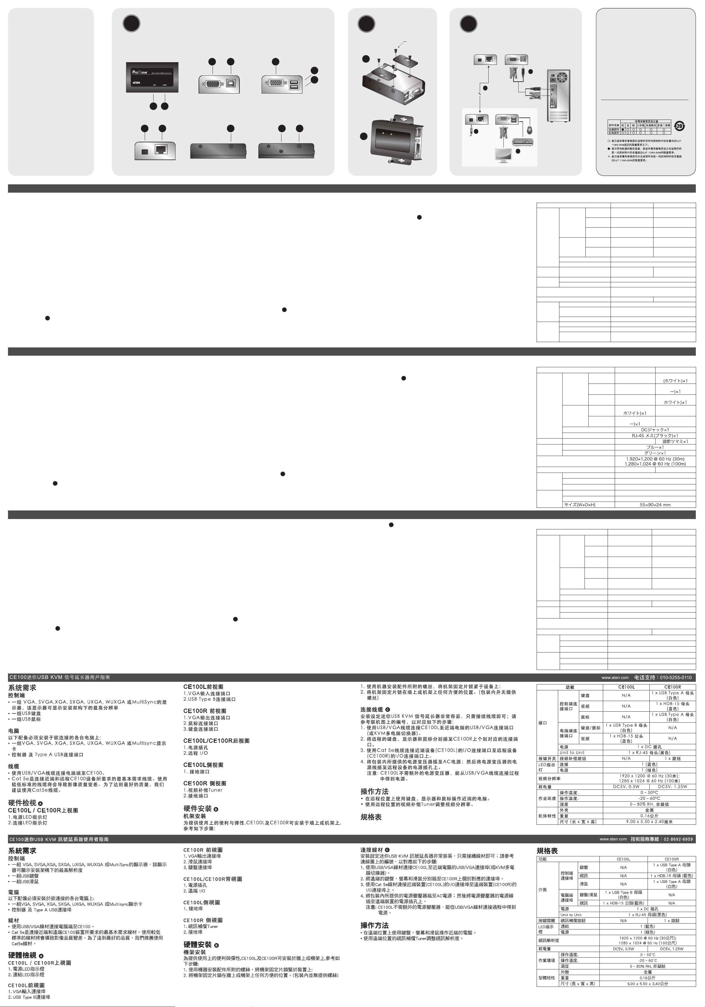
하드웨어 리뷰 A
CE100L / CE100R 상단부
1. 전원(Power) LED
2. 링크(Link) LED
CE100L 전면부
1. VGA 입력 포트
2. USB B타입 포트
システム要件
コンソール
•
製品に接続して使用するコンピューターの解像度に適した、VGA、SVGA、
XGA、SXGA、UXGA、WUXGAまたはマルチシンク対応モニター
•
USBキーボード
•
USBマウス
コンピューター
製品に接続して使用するコンピューターには、下記のハードウェア環境が
必要です。
•
VGA、SVGA、XGA、SXGA、UXGA、WUXGA、またはマルチシンク
対応カード
•
USBホストコントローラーおよびUSBタイプAポート
ケーブル
•
USB/VGAケーブルで各機器を接続してください。
•
CE100のローカル/リモートユニットを接続するには、カテゴリ5e以上
のケーブルが必要になります。この規格に満たないケーブルを使用した
場合、ビデオ信号の劣化につながるおそれがあります。最適な状態でお
使い頂くために、カテゴリ5eケーブルの使用を強く推奨します。
製品各部名称
A
CE100L/CE100R上面
1.電源LED
2.リンクLED
CE100L Vista anteriore
1. Porta d’ingresso VGA
2. Porta USB di tipo B
CE100R Vista anteriore
1. Porta d’uscita VGA
2. Porta mouse
3. Porta tastiera
CE100L/CE100R Vista posteriore
1. Presa d’alimentazione
2. I/O remoto
CE100L Vista laterale
1. Terminale di messa a terra
CE100R Vista laterale
1. Sintonizzatore per la compensazione video
2. Terminale di messa a terra
Installazione dell’hardware B
Montaggio
Per una maggiore comodità e fl essibilità, i dispositivi CE100L e CE00R
possono essere montati su parete oppure in rack, come segue:
1. Utilizzando le viti fornite con il kit di montaggio in rack, avvitare le staffe
sotto al dispositivo come illustrato in fi gura.
CE100R 전면부
1. VGA 출력 포트
2. 마우스 포트
3. 키보드 포트
CE100L/CE100R 후면부
1. 전원 잭
2. 원격 I/O
CE100L 측면부
1. 접지 터미널
CE100R 측면부
1. 비디오 보정
2. 접지 터미널
하드웨어 설치 B
마운팅
제품의 유연성 및 편의성을 위해, CE100L과 CE100R 제품을 시스템 랙에
마운트하여 사용할 수 있습니다 :
1. 랙 마운트 키트에서 제공하는 스크류를 사용하여 다음 그림과 같이 마운
팅 브라켓을 유닛 하단에 고정하십시오.
2. 브라켓을 벽 또는 랙의 설치할 장소에 스크류로 고정하십시오. (이 스크
류는 포함되지 않습니다.)
CE100L前面
1.VGA入力ポート
2.USBタイプBポート
CE100R前面
1.VGA出力ポート
2.マウスポート
3.キーボードポート
CE100L/CE100R背面
1.電源ジャック
2.リモートI/O
CE100L側面
1.グランドターミナル
CE100R側面
1.ビデオ補正チューナー
2.グランドターミナル
ハードウェアのセットアップB
製品のマウント
CE100LおよびCE100Rは、壁やシステムラックに自由にマウントして、
便利にお使い頂くことができます。マウント方法は下記の通りです。
1.ラックマウントキットに付属されたネジを使って、マウント用ブラケッ
トを下図の位置(ユニット底面)に取り付けてください。
2. Avvitare le staffe nella posizione desiderata sulla parete o sul rack. (Le
viti per il montaggio in rack non vengono fornite.)
Connessione dei cavi
C
Impostare il sistema d’espansione Mini USB KVM consiste semplicemente
nel collegare i cavi. Vedere lo schema di installazione (i numeri nello
schema corrispondono ai passaggi) durante l'esecuzione dei passaggi:
1. Utilizzare il cavo USB/VGA per collegare il CE100L alla porta USB/VGA
del computer locale (o dello switch KVM).
2. Collegare la tastiera remota, il monitor e il mouse alle rispettive porte sul
CE100R.
3. Utilizzare il cavo Cat 5e per collegare la porta I/O dell’unità locale
(CE100L) alla porta I/O dell’unità remota (CE100R).
4. Inserire l’alimentatore (in dotazione) in una presa di corrente CA, quindi
inserire il cavo dell’alimentatore nella presa d’alimentazione del CE100R.
Nota: Il CE100L non richiede un alimentatore poiché viene alimentato
tramite il collegamento USB/VGA.
Funzionamento
• Utilizzare tastiera, monitor e mouse remoti per comandare il computer
locale.
• Regolare la qualità video dello schermo remoto tramite il sintonizzatore
per la compensazione video.
케이블 연결 C
Mini USB KVM 확장기 시스템을 설치하는 방법은 케이블 연결로 매우 간단
히 설치됩니다. 단계별로 표시된 설치그림을 참고하여 다음과 같이 설치하
십시오 :
1. USB/VGA 케이블을 사용하여 CE100L 제품과 로컬 컴퓨터의 USB/VGA
포트를 연결하십시오. (또는 KVM 스위치에 연결하십시오).
2. 원격 키보드, 마우스를 CE100R 제품의 각 해당 포트에 연결하십시오.
3. Cat 5e 케이블을 사용하여 로컬 유닛(CE100L) I/O 포트와 원격 유닛
(CE100R) I/O 포트를 연결하십시오. .
4. 패키지에서 제공하는 전원 어댑터를 AC 전원에 연결하십시오. 그런 다
음, 어댑터 케이블을 CE100R 제품의 전원 잭에 연결하십시오.
알림: CE100L 제품은 USB/VGA 연결로부터 전원을 공급받기 때문에 별
도의 전원 어댑터가 필요 없습니다.
작동 방법
• 로컬 장소의 컴퓨터를 작동하려면 원격 장소에서 키보드, 모니터, 마우스
를 사용하십시오.
• 비디오 품질을 보정하려면 원격 장소에서 디스플레이 비디오 품질을 조절
하십시오.
2.このブラケットを、壁やラックの使いやすい位置にネジで固定してくだ
さい。(これらのネジは製品には同梱されていません。)
ケーブルの接続
C
本製品のセットアップは、必要なケーブルを接続するだけですので簡単で
す。以下の接続図(図内における番号は手順に対応)を参考にしながら、下
記の手順に従ってセットアップを行ってください。
1.USB/VGAケーブルを使って、CE100Lをローカルコンピューター(また
はKVMスイッチ)のUSB/VGAポートに接続してください。
2.リモート側で使用するキーボード・モニター・マウスを、CE100R上の
対応ポートにそれぞれ接続してください。
3.カテゴリ5eケーブルを使って、ローカルユニット(CE100L)のI/Oポー
トとリモートユニット(CE100R)のI/Oポートを接続してください。
4.製品に同梱されている電源アダプターをCE100Rの電源ジャックに接続
し、アダプター部分をAC電源に接続してください。
注意:CE100LにはUSB/VGAケーブルを介して給電されますので、こ
のユニットには電源アダプターが不要です。
操作方法
•
ローカル側のコンピューターは、リモート側のキーボード・モニター・
マウスを使って操作してください。
•
リモート側の表示画質は、ビデオ補正チューナーを使って調整してくだ
さい。
Specifi che
Funzione CE100L CE100R
Connettori
Porte di
collegamento
alla console
Tastiera No
1 femmina USB di tipo
A (bianco)
Video No
1 connettore femmina
HDB-15 (blu)
Mouse No
1 femmina USB di tipo
A (bianco)
Porte KVM
Tastiera/
Mouse
1 femmina USB di tipo
B (bianco)
No
Video
1 maschio HDB-15
(blu)
No
Alimentazione 1 connettore CC
Da dispositivo a dispositivo 1 connettore femmina RJ-45 (nero)
Switch
al rep erot azzinotniS
oediv enoiz asnepmoc
No 1 manopola
LED
Link 1 (blu)
Alimentazione 1 (verde)
Video
1920 x 1200 @ 60 Hz (30m);
1280 x 1024 @ 60 Hz (100m);
Consumo elettrico CC5V; 0,5W CC5V; 1,25W
Condizioni
ambientali
Temperatura operativa 0 ~ 50ºC
Temperatura di
conservazione
-20 ~ 60ºC
Umidità Da 0 a -80% umidità relativa, senza condensa
Proprietà
fi siche
Case Metallo
Peso 0,16 kg
Dimensioni
(lungh. x largh.x alt.)
9,00 x 5,50 x 2,40 cm
제품 사양
기능 CE100L CE100R
커넥터
콘솔 포트
키보드 N/A
1 x USB Type A
Female (White)
비디오 N/A
1 x HDB-15 Female
(Blue)
마우스 N/A
1 x USB Type A
Female (White)
KVM 포트
키보드 /
마우스
1 x USB Type B
Female (White)
N/A
비디오
1 x HDB-15 Male
(Blue)
N/A
전원 1 x DC Jack
유닛-유닛 연결 1 x RJ-45 Female (Black)
스위치 수동 증폭 제어 N/A 1 x Knob
LED
링크(Link) 1 (Blue)
전원(Power) 1 (Green)
비디오
1920 x 1200 @ 60 Hz (30m);
1280 x 1024 @ 60 Hz (100m)
전력 소비 DC5V, 0.5W DC5V, 1.25W
사용 환경
작동 온도 0–50ºC
보관 온도 -20–60ºC
습도 비응축 상태에서 0–80% RH
물리 환경
재질 금속
무게 0.16 kg
크기 (L x W x H) 9.00 x 5.50 x 2.40 cm
製品仕様
機能 CE100L CE100R
コネクター
コンソール
ポート
キーボード N/A
USBタイプAメス
モニター N/A
D-sub15メス(ブル
マウス N/A
USBタイプAメス(
KVMポート
キーボード
/マウス
USBタイプBメス(
N/A
モニター
D-sub15オス(ブル
N/A
電源
ユニット間接続
スイッチ ビデオ補正チューナー N/A
LED
リンク
電源
解像度
消費電力 DC5V、0.5W DC5V、1.25W
動作環境
動作温度 0〜50ºC
保管温度 -20〜60ºC
湿度 0〜80%RH、結露なきこと
本体
ケース材料 メタル
重量 160g
www.aten.com
www.aten.com
ww w.a te n.com P ho ne : 02-46 7- 67 89
 Loading...