

Page 1

AS/2 AUTO SWITCH
AS-401Pii/AS-402Pii
User’s Manual
Copyright 1991 ATEN® International CO., LTD.
Manual Part No PA PE-0094-2 00
Page 2

NOTICE
This manual is written for the Auto Switch AS-40lPit and AS-402Pii,
General operations of these two models are the same and differences will be
specified for related models.
In this manual, 'AS/2' is used to represent both models of AS-401 Pii and
AS-402P1I. When you purchase this product it should contain the following
items,
PACKAGE CHECKLIST
• An AS/2(any one of AS-401 Pi«/AS-402Pii)
• The Power Adapter spec, depends on the following product model
Model
AS-401 Pii
AS-402PII
Spec.
DC 9V 20OmA*
DC 9V 200inA
*Adapter comes with buffer card
A 5 1/4' (or 3 1/2") Floppy Diskette with AS/2-WARE, Hot Key
Control Programs (suitable for IBM PC/XT/AT, DOS V 3 0 or later)
NOTE: AS/2-WARE is offered for AS-402Pii only.
An AS/2 Auto Switch User’s Manual
QUICK LOOK INTERFACE TABLE
MODEL ! INPUT PORT
AS-401 Ri 4 CENTRONICS Female
AS-402Pii 1 4 CENTRONICS Female
1 CENTRONICS Female N0
2 CENTRONICS Female
OUTPUT PORT SUPPORTED
AS/2-WARE
Yes
Page 3

AS/2 Auto Switch
FUNCTION OVERVIEW
_______________
1 FUNCTION OVERVIEW
1-1 Introduction........................................................................................ 1
1 -2 Function Specifications ...................................................................... 4
1- 3 Product Limitation .................................................................................5
2 INSTALLATION
2- 1 Installation Procedure ...........................................................................6
2-2 DIP Switch Setting .................................................................................8
2- 3 AS Buffer Card Installation....................................................................9
3 POWER ON PROCEDURE
3- 1 Power On Procedure ......................................................................... 10
3-2 Auto Switching Mode ..........................................................................10
3- 3 Manual Switching Mode .....................................................................11
4 AS/2-WARE
4- 1 AS/2-WARE, Hot Key Control Programs
4-2 How to Use the AS/2-WARE ...............................................................12
TABLE OF CONTENTS
............................................
____________
12
1 FUNCTION OVERVIEW
1-1 INTRODUCTION
The AS/2 is a high performance and low cost printer sharing device
which can operate in either auto switching mode or manual switching mode.
The AS/2 has buffer card option. In the auto switching mode the AS/2 automat
ically locks on and services the source device that requests to link to the
common destination device. However, in the manual switching mode the AS/2
works exactly the same way as the conventional data switch.
1-1-1 AS-401PII
AS-401PII is a 4-input-1-output Centronics auto switch, which does not
require additional power supply should no buffer card installed and needs DC
9V adapter If installed. Also, it is not AS/2-WARE supported.
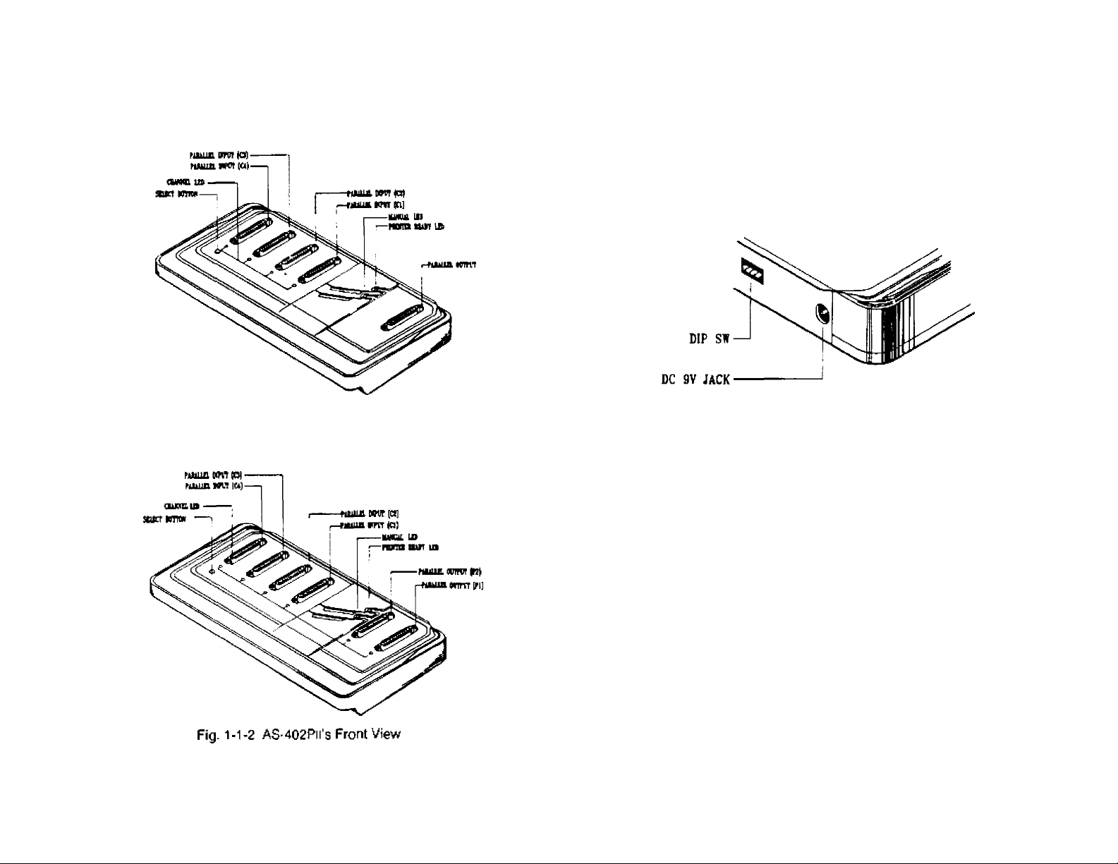
1-1-2 AS-402PII
AS-402PII is a 4-input-2-output Centronics auto switch, and is AS/2-
WARE supported, which enables user to choose output port by simple Hot Key
controls. AS-402PII is powered by one DC 9V adapter with or without buffer.
The AS/2 tremendously improves the efficiency of your switching
applications. We suggest that you take a few moments to carefully read the
following instructions to ensure the maximum benefits and convenience your
AS/2 offers The following figures are the AS/2's front views ard rear views.
APPENDIX A Troubleshooting ............................................................................14
APPENDIX B Centronics Interface Timing Chart ...............................................15
APPENDIX C Preventing Radio & TV Interference ...........................................,16
User's Manual
Page 4
FUNCTION OVERVIEW
Fig. 1*1-1 AS-401 Pii’s Front View
AS/2 Auto Switch
AS/2 Auto Switch
NOTE; The rear view of AS/2 is identical to all models
FUNCTION OVERVIEW
Fig. 1-1-5 AS/2's Rear View
User's Manual User's Manual
Page 5

FUNCTION OVERVIEW
1-2 FUNCTJON SPECIFICATIONS
FUNCTIONS
Power Supply Non-powered*
Cable Distance
CONNECTOR
(DB-25)Female
Input Status 4
Output Status
LED Printer Ready
L
Buffer Card
(Optional)
Input Arbitration First Come, First Serve
Function Key
Input Port Selection
Output Port Selection
Time out Selection
Auto Form Feed
Operation Temp.
Stock Temp.
Humidity 0%-80%
Enclosure Plastic and Metal.
Weight
Dimensions
INPUT
OUTPUT 1 CENTRONICS
Manual
AS/2 Auto Switch
PARALLEL MODEL
AS-401 Pii
AS-402PII
DC 9V, 200mA
9M
4 CENTRONICS
2 CENTRONICS
4
None
1
1
2
1
1
256K/1M/2M Bytes
(Support output port #1 only)
Manual Select
Auto or Manual
□ IP SW A AS/2 -WARE
None j
5 - 60 sec.
Enabled/Disabled
5"c - 40''c
-20"c - 60°c
iKg
270x145x34.5 mm"
AS/2 Auto Switch
FUNCTION OVERVIEW
1-3 PRODUCT LIMITATION
AS/2 is a well designed quality product, Its maximum performance and
limitation is described as follows.
AS/2's Manual Switching Mode is suitable for all kinds of Hand
shaking Modes.
For model AS-402PH and AS-401 P«i, the cable length is limited to no
more than 9 meters
The parallel interface mentioned on this manual are Centronics
interfaces (please refer to appendix 8).
AS/2 is IBM PC/AT/XT compatible.
Buffer card installed In AS-40£Pii is to support output port #1 only.
* AS-401 Pi( needs DC 9V 300mA adapter if buffer card installed,
F|g,-(-2H AS-40lPl|/AS^02PirsFunctiorSpecifications
User's Manual
User's Manual
Page 6

INSTALLATION
2 INSTALLATION
2-1 JNSTALLATION PROCEDURE
2-1 '1 Cable Connection Table
AS-401PIÌ , 4ÌN/10UT see Fig. on page 7
AS/2 Auto Switch
AS/2 Auto Switch
INSTALLATION
AS-402Pil 1 4IN/2 OUT
____________
1
see Fig. 2-1 -2 on page 7
2-1-2 Parallel Port Cabling
Device ' s Pin # 25- ptn/25- pi ri ca PI e AS/2 Auto Switc h
DB-251' C-36
1
2-9 2-9
10
10
11 11
or 36-pin/25-pin cable
STROBE
DO - D7
AC K
BUSY
■
12
13 13
14 14
15 32
12
PE
SLCT
AÜTOFEEO-XT
ERROR
DB-25
1
2-9
10
11
12
13
14
15
PRETER
Fig. 2-1-1 AS-40lPn’s 4 IN/1 OUT Configuration
?c| (PC
MuJ
J C
PARALLEL
P&KT
J [
PAi^Aim
FORT
pPC
J L
PAIÎAUEL
PORT
|pc|
FUULLEL
PORT
,tB-ÎS CABLE
AS/2 AS-402Pn
PABALLEl
PORT
padaoel
POhT
16 31
17
36
16-25 19-30
INIT
SLCT-IN
GND
ie
17
13-25
User's Manual
PR1^TER RHINTER
Fig. 2-1 -2 AS^Û2Pi«'s 4 IN/2 OUT Configuration
User's Manual
Page 7

INSTALLATION
AS/2 Auto Switch
AS/2 Auto Switch
INSTALLATION
2-2 DIP SWITCH SETTING
While the AS/2 powers on. it reads the status of the DIP switch and
executes to the functiori setting which is shown in the foUowing figure. The
Default Setting of the AS/2 is marked by shadow area, The Output Fort Setting
is only available to the AS-40£Pii. The Output Port Setting is effective only at
power on. The user may change the Output Port Setting at any time by using
the AS/2-WARE, For detailed information please refer to Section 4^f, 4-2.
6 5 4 3 2 1
2-3 AS Buffer Card installalion
AS buffer card has 64K. 256K or 1M bytes of memory and is used to
expand the buffer memory of AS-401 Ph and AS-402Pii auto switches.
Installation procedures are the same for different memory size buffer
cards:
1) Unscrew the 5 screws pointing to by arrows on the metal chassis.
2) Place the plastic cover up side down as in Fig. 2.3
3) Find the 14 X 2 goid pin connector on the PCB of the AS auto switch,
4) Connect The AS buffer card's 14x2 gold pin connector to that of the
AS auto switch's.
5) Secure the two plastic spacers to both RGBs.
6) Place the plastic cover back to the metal chassis and secure the 5
screws back to complete the buffer card installation.
Fig 2-2-1 AS/2 Auto Switch’s DIP Switch Setting
NOTE; TheDiPSwitchSettingwiththeshadowmarksaretheAS/2‘s
defaults.
User’s Manual
Fig. 2.3 Piace the plastic cover
User's Manual
Page 8

POWER ON PROCEDURE AS/2 Auto Switch
AS/2 Auto Switch POWER ON PROCEDURE
3 POWER ON PROCEDURE
3-1 POWER ON PROCEDURE
1) To reset the AS-402Pii and AS-40lPii (w^buffer card), simply unplug
the DC 9V power adapter from the power jack and plug it ir again.
AS-401PII (w/o buffer card) can be reset by recycling printer power
while it is hooked to a printer.
Caution: Make sure you are using the right power adapter as listed
in the section 1-2 Function Specifications.
2) After power is reset, the input channel's service LEDs are on.
Meanwhile, the AS/2 is ready for operation and it enters the auto
switching mode automatically.
3-2 AUTO SWITCHING MODE
t) In autc switching mode, the user will see all the input channel's service
LEDs turn on, That means the AS/2 stands by to get data from all
channels.
2) If any channel of’CT, C2'.‘C3’ and’C4‘ requests to be served, the
requested channel‘s LEO will be on arKl the AS/2 will lock on to that
channel. At this moment the output port of AS/2 wifi only serve the
locked input chartnel until all the input data from the requested channel
has been sent out arid aiso the time out period is up. The time out
setting depends on the current DiP Switch's Setting on AS/2.
3) When the ‘READY’ LED turns off, it indicates
Connectors are not properly connected,
Prlnier(or output device) is not switched on.
Printer is not in ON-LINE status,
or. Printer is out of paper.
If buffer card installed for output 1 ’READY" LEO reflects buffer
readiness.
The user is therefore requested to make corrections accordingly
before going any further with the procedures,
4) When the AS/2 is serving a certain input channel, it does not switch to
sen/e another channel even though the printing gets interrupted by
the printer power off or out of paper, etc.
NOTE: Only in the ManuaJ Switching Mode user can force the AS/2
to switch to and service another input channel,
3-3 MANUAL SWITCH I MG MODE
Press 'SELECT' several times to instruct AS/2 cycles through
manual switching mode and auto switching modes in the following
sequence: 1-2-3-4-5-1-2-3
Cycle#
1 Auto ON ON ON ON OFF
2
3
4
5
Furclitui 'CVLEO ’C£‘ LED ■C3- LED
Manual C/1
Manual OFF ON OFF OFF ON
Manual C#3
Manual C#4 OFF
........
04’ LED
ON OFF OFF OFF ON
OFF OFF ON OFF ON
OFF OFF
ON ON
MANUAL LED
10
User's Manual
Jser's Manual
11
Page 9

AS/2 -WARE (For AS-402PII Only) AS/2 Auto Switch
AS/2 Auto Switch
AS/2 -WARE (For AS-402FH Only)
4 AS/2 -WARE (For AS-402PII Only)
4-1 AS/2-WARE, HOT KEY CONTROL PROGRAMS
The AS/2-WARE contains few neskient eiiecution files which function tike
a hot key controller- it performs functions like selecting the desired port for
user's application and broadcasting the input data to all output ports by
pressing two or three specified keys at the same time. The detailed information
will be explained in the next section-
4-2 HOW TO USE THE AS/2-WARE
There is a diskette named AS/2-WARE which is enclosed within the
product- This section will instruct you on how to use the AS/2-WARE with the
AS/2.
Assuming your floppy disk drive is In drive "A", insert the diskette into the
floppy drive A and type:
or where the '2' mea ns the ’ LPT2 '.
The AS/2-WARE supports more than three sets of Hot Keys for the user
in case of some applications using the same keys. The following descriptions
are one set of Hot Keys and their operating methods.
A) Switch to Port A:
etri L-Sht
[
B) Switch to Port B;
etri L-Sht
+ 6
e) Broadcast to Port A and Port B;
Ctrl L-Sht
When the AS/2-WARE program is loaded, user can press the Hot Keys
to switch the output port to the desired one at any time.
There are three kinds of choices the user has to switch the AS/2 Auto
Switch by using the AS/2-WARE. They are
* Switch output port to Port A,
* Switch output port to Port B, and
* Broadcast data to two output ports, Port A and Port B,
The more detailed information about AS/2-WARE is saved in "READ.ME'
file which can be found in the AS/2-WARE Floppy diskette.
If the user has any product support issues or questions, pfease call your
dealer for assistance.
Note: <L Sht> means the Left Shift key.
12 User's Manual User's Manual 13
Page 10

APPENDIX A
APPENDIX B
TROUBLE SHOOTiNG
PROBLEM
LEO fails to light up
Failure of data
transmission
It failure of printing is still exists upon aforesaid solutions, ptease
contact your dealer for help.
1 SOLUTIONS
Check if power is turned ON or not
1. Check if the Connector of each cable is well
plugged or not.
2. Check if PC is turned ON o.r not,
3- Check if PRINTER is turned ON or not.
4. Check if paper for PRINTER is well prepared
or not.
5 Check if Print command on PC is correct or
not.
6. Check if connect on computer end has been
connected in accordance with menu,
CENTROWrCS INTERFACE TIMING CHART
14
User’s Manual
User’s Manual
15
Page 11

APPENDIX C
PREVENTING RADIO & TV INTERFERENCE
Warning this equipment generates, uses and radiates radio frequency
energy and if not installed and used in accordance with the instruction manual
may cause interference to radio and television reception. It has been tested and
found to comply with the limits for a Class A computing device in accordance
with the specifications in Subpart J of Part 15 of FCC Pules, which are
designed to provide reasonable protection against such interference when
operated in a commercial environment. Operation of this equipment in a
residential area Is likely to cause interference, in which case the user at
his own expense will be required to take whatever measures may be required
to correct the interference.
Ifthis equipment does cause interference to radio ortelevision reception,
which can be determined by turning the equipment off and on, the user is
encouraged to try to correct the interference by one or more of the following
measures:
1. Reorient the reveiving antenna.
2. Relocate the computer with respect to the receiver.
3. Move the computer away from the receiver.
4. Plug the computer into a different outlet so that computer and receiver
and on different branch circuits.
5. Ensure that the mounting screws, attachment connector screws and
ground wires are tightly secured.
6. Ensure that good quality, shielded and grounded cables are used for
data communications-
If necessary, the user should consult the dealer or an experienced
radio/television technician for additional suggestions.
16
User’s Manual
 Loading...