

User Manual
ACS-1208AL
ACS-1216AL
Warning!
This is a class A product. In a domestic environment this product may cause radio
interference in which case the user may be required to take adequate measures.
This equipment has been tested and found to comply with the limits for a Class A
digital device, pursuant to Part 15 of the FCC Rules. These limits are designed to
provide reasonable protection against harmful interference when the equipment is
operated in a commercial environment. This equipment generates, uses and can
radiate radio frequency energy and, if not installed and used in accordance with
the instruction manual, may cause harmful interference to radio communications.
Operation of this equipment in a residential area is likely to cause harmful
interference in which case the user will be required to correct the interference at
his own expense.

Packing List
ACS-1208AL / ACS-1216AL User Manual
The complete ACS-1208AL / ACS-1216AL package consists of:
M 1 ACS-1208AL or ACS-1216AL KVM Switch
M 2 Custom KVM Cable Sets (2L-5202P)
M 1 Firmware Upgrade Cable
M 1 Power Adapter with Power Cord
M 1 User Manual
M 1 Quick Start Guide
M 1 Rack Mounting Kit
Check to make sure that all the components are present and that noth ing
got damaged in shipping. If you encounter a problem, contact your
dealer.
Read this manual thoroughly and follow the installation and operation
procedures carefully to prevent any damage to the unit, and/or any of
the devices connected to it.
© Copyright 2003 ATEN® International Co., Ltd.
Manual Part No. PAPE-0212-2AT
Printed in Taiwan 11/2003
All brand names and trademarks are the registered property of their respective owners.
iii

ACS-1208AL / ACS-1216AL User Manual
Table of Contents
1. Introduction
Overview . . . . . . . . . . . . . . . . . . . . . . . . . . . . . . . 1-1
Features . . . . . . . . . . . . . . . . . . . . . . . . . . . . . . . . 1-3
Hardware Requirements . . . . . . . . . . . . . . . . . . . . . . . 1-4
Computers . . . . . . . . . . . . . . . . . . . . . . . . . . . . 1-4
Cables . . . . . . . . . . . . . . . . . . . . . . . . . . . . . . 1-4
ACS-1208AL / ACS1216AL Front View . . . . . . . . . . . . . . . . 1-6
ACS-1208AL / ACS-1216AL Rear View . . . . . . . . . . . . . . . 1-8
LCD OSD Configuration . . . . . . . . . . . . . . . . . . . . . . . 1-10
2. Installation
Before you Begin . . . . . . . . . . . . . . . . . . . . . . . . . . . 2-1
Single Stage Installation . . . . . . . . . . . . . . . . . . . . . . . 2-1
Daisy Chaining . . . . . . . . . . . . . . . . . . . . . . . . . . . . 2-2
Hot Plugging . . . . . . . . . . . . . . . . . . . . . . . . . . . . . 2-5
Port ID Numbering . . . . . . . . . . . . . . . . . . . . . . . . . . 2-6
Powering Off and Restarting . . . . . . . . . . . . . . . . . . . . . 2-7
Port Selection . . . . . . . . . . . . . . . . . . . . . . . . . . . . . 2-7
3. Hotkey Operation
Hotkey Port Access . . . . . . . . . . . . . . . . . . . . . . . . . 3-1
Invoking Hotkey Mode . . . . . . . . . . . . . . . . . . . . . . 3-1
Selecting the Active Port . . . . . . . . . . . . . . . . . . . . . 3-2
Auto Scanning . . . . . . . . . . . . . . . . . . . . . . . . . . 3-3
Skip Mode . . . . . . . . . . . . . . . . . . . . . . . . . . . . 3-5
Hotkey Beeper Control . . . . . . . . . . . . . . . . . . . . . . 3-6
Hotkey Summary Table . . . . . . . . . . . . . . . . . . . . . 3-6
4. OSD Operation
OSD Operation . . . . . . . . . . . . . . . . . . . . . . . . . . . . 4-1
OSD Overview . . . . . . . . . . . . . . . . . . . . . . . . . . 4-1
OSD Navigation . . . . . . . . . . . . . . . . . . . . . . . . . 4-3
OSD Main Screen Headings . . . . . . . . . . . . . . . . . . . 4-3
OSD Functions . . . . . . . . . . . . . . . . . . . . . . . . . . 4-4
iv

5. The Firmware Upgrade Utility
Introduction . . . . . . . . . . . . . . . . . . . . . . . . . . . . . . 5-1
Purpose . . . . . . . . . . . . . . . . . . . . . . . . . . . . . . 5-1
Before You Begin . . . . . . . . . . . . . . . . . . . . . . . . . 5-2
Performing the Upgrade . . . . . . . . . . . . . . . . . . . . . . . . 5-3
Starting the Upgrade . . . . . . . . . . . . . . . . . . . . . . . 5-3
Upgrade Succeeded . . . . . . . . . . . . . . . . . . . . . . . 5-6
Upgrade Failed . . . . . . . . . . . . . . . . . . . . . . . . . . 5-6
Firmware Upgrade Recovery . . . . . . . . . . . . . . . . . . . . . 5-7
Appendix A, Technical Information
ACS-1208AL / ACS-1216AL - Connection Tables . . . . . . . . . . A-1
ACS-1208AL . . . . . . . . . . . . . . . . . . . . . . . . . . . A-1
ACS-1216AL . . . . . . . . . . . . . . . . . . . . . . . . . . . A-2
OSD Factory Default Settings . . . . . . . . . . . . . . . . . . . . . A-2
Specifications . . . . . . . . . . . . . . . . . . . . . . . . . . . . . A-3
Clear Login Information . . . . . . . . . . . . . . . . . . . . . . . . A-4
Troubleshooting . . . . . . . . . . . . . . . . . . . . . . . . . . . . A-5
Limited Warranty . . . . . . . . . . . . . . . . . . . . . . . . . . . A-5
ACS-1208AL / ACS-1216AL User Manual
Appendix B, Module Removal
Removing the KVM Module . . . . . . . . . . . . . . . . . . . . . . B-1
Removing the Keyboard and Touchpad . . . . . . . . . . . . . . . . B-2
Appendix C, Rack Mounting
Standard Rack Mounting . . . . . . . . . . . . . . . . . . . . . . . C-1
Optional Rack Mounting . . . . . . . . . . . . . . . . . . . . . . . . C-2
v

ACS-1208AL / ACS-1216AL User Manual
About This Manual
This User Manual is provided to help you get the most from your
ACS-1208AL / ACS-1216AL system. It covers all aspects of installation, configuration and operation. An overview of the in formation found
in the manual is provided b elo w.
Overview
Chapter 1, Introduction, introduces you to the ACS-1208AL /
ACS-1216AL System. Its purpose, features and benefits are presented,
and its front and back panel components are described.
Chapter 2, Installation explains how to set up your installation — from
a basic single stage hookup to a complete 32 switch daisy chained
operation.
Chapter 3, Hotkey Operation, details all of the concepts and
procedures involved in the Hotkey operation of your ACS-1208AL /
ACS-1216AL installation.
Chapter 4, OSD Operation, provides a complete description of the
ACS-1208AL / ACS-1216AL’s OSD (On Screen Display), and how to
work with it.
Chapter 5, The Firmware Upgrade Utility, explains how to use this
utility to upgrade the ACS-1208AL / ACS-1216AL’s firmware with the
latest available versions.
An Appendix at the end of the manual provides specifications and other
technical information regarding the ACS-1208AL / ACS-1216AL.
vi

ACS-1208AL / ACS-1216AL User Manual
Conventions The following typographical conventions are used throughout this manual:
M Bullet lists provide information, but not procedural step s.
1. Numbered lists represent procedures with sequential steps.
An indented typeface like the one below:
Key information in
indicates words and characters you key in. Unless otherwise mentioned,
you can use either upper or lower case.
The names of the keys you should press are placed inside of square
brackets, and appear just as they do on the keyboard (for ex ample, [Alt],
[Enter], [Esc]). Don’t type the brackets or anything that appears inside
of them, just press the key. For example, if a procedure tells you to type:
Install [Enter]
You should type the word Install in either upper or lower case, then press
the Enter key.
If you need to hold down one key and, while you are holding it down,
press another key, the keys appear in square brackets with a dash
between them. For example, [Ctrl-Alt-Del] means to hold down th e Ctrl
and Alt keys and, while they are being held down, press the Del key and
then release all the keys together.
If you are asked to Choose or Select an item listed on a menu, Click it
with the mouse. An alternate shortcut method is to press the appro priate
accelerator key combination indicated on the men u.
vii

ACS-1208AL / ACS-1216AL User Manual
Notes:
viii

his chapter introduces you to the ACS-1208AL / ACS-1216AL KVM Switch. Its
T
purpose, features and benefits are presented, and its front and back panel comp o-
nents are described.
Overview
Chapter 1.
Introduction
The Master View ACS-1208AL and ACS-1216AL KVM Switches are
control units that allow access to multiple computers from a single
console (keyboard, mouse, and mo nitor). Before the development of th e
Master View, the only way to control multiple computer configuratio ns
from a single console was through a complex and costly network system.
Now, with the Master View ACS-1208AL and ACS-1216AL, you can
easily access multiple computers in a cost effective manner.
A single Master View ACS-1208AL or ACS-1216AL can control up to
8 or 16 computers, respectively. As many as 31 additional Master View
units can be daisy chained to each other, so that up to 512 computers
can all be controlled from a single keyboard-monito r-mouse console.
The Master View ACS-1208AL / ACS-1216AL offers a space-saving,
streamlined approach to KVM switch technology by integrating a
keyboard, LCD monitor, and touchpad in a Slideaway housing. The
LCD display is built into the cover; the keyboard and touch pad are built
into the base. Slide the KVM module section out; flip the co ver up; and
you are ready to go to work. When finished, simply flip the cover down
and slide the KVM module away.
For further convenience, the Slideaway housing is 1U high for easy
rack mounting. The ACS-1208AL / ACS-1216AL also features high
density 15 pin connectors instead of the usual 25 pin connectors. This
space-saving innovation allows a full, 16 port switch to be installed in
1-1

ACS-1208AL / ACS-1216AL User Manual
a 1U system rack. Because of its modular design, the KVM section can
be detached from the switch section. If you ever need to expand your
connections, you can remove the 8 port Switch module; and replace it
with a 16 port Switch module.
Your ACS-1208AL / ACS-1216AL investment is protected by an
included Firmwa re Upgrade Utility. You can stay current with the latest
functionality improvements by downloading firmware update files from
our website as they become available, and using the utility to quickly
and conveniently perform the upgrade.
Setup is fast and easy; plugging cables into th eir appropriate ports is all
that is entailed. Because the ACS-1208AL / ACS-1216AL intercepts
keyboard input directly, there is no software to configure; no need to get
involved in complex installatio n routines; nor any need to be co ncerned
with incompatibility problems.
Access to any computer connected to the installation is easily accomplished either by entering Hotkey combinations from the keyboard, or
by means of a powerful mouse driven OSD (On Screen Disp lay ) men u
system. A convenient Auto Scan feature also permits automatic scanning
and monitoring of the activities of all computers running on the installation one by one.
There is no better way to save time and money than with a Master View
ACS-1208AL / ACS-1216AL installation. By using the Master View
ACS-1208AL / ACS-1216AL with its Slideaway console to manage
your installation, you: (1) eliminate the expense of having to purchase
a separate keyboard, monitor, and mouse for each computer; (2) save
all the space those extra components would take up; (3) save the space
that a keyboard, monitor, and mouse would take with a standard KVM
switch; (4) save on energy costs; and (5) eliminate the inconvenience
and wasted effort involved in constan tly mo vin g fro m one comp uter to
another.
1-2

Features
Introduction
w Integrated KVM Console with 15" LCD Monito r - In a 1U Hig h
Slideaway Housing For Convenient Rack Mountin g
w Space Saving Technology - A Single Console Controls Up To 8
(ACS-1208AL) or 16 (ACS-1216AL) Computers
w Daisy Chain Up To 31 Additional Units - Co ntro l Up to 512
Computers From the Unit’s Integrated Slideaway Console
w Modular Design - Console Detaches From the Switch Ch assis fo r
Easy Maintenance
w Keyboard/Touchpad Module is Easily Removed fo r Qu ick Repair
or Replacement - Eliminates Lengthy Down Times - No Need to
Return the Switch to the Factory
w No Software Required - Convenient Computer Selection via
Hotkeys and Mouse Driven Intuitive On Screen Display (OSD)
Menus
w Auto Scan Feature for Monitoring User-S elected Co mp uters
w Hot Pluggable - Add or Remove Computers Without Hav in g T o
Power Down the Switch
w Daisy Chained Station Positions Auto-S en sed - No Manual DIP
Switch Setting - Front Panel LED Indicates Station Position
w Port Names Automatically Reconfigured When Station Seq uence
Changes
w Two Level Password Security - Only Authorized Users View and
Control the Computers - Up to Four Users Plus an Administrator
with Separate Profiles For Each
w Two Level Logout - Manual and Timed
w PS/2 Keyboard and Mouse Emulation - Computers Bo ot Even
When the Console Focus is Elsewhere
w Superior Video Quality - Supports Resolutions of Up To 1024 x 768
w DDC Emulation of the LCD Monitor - VGA Settings of Every
w Upgradable Firmware
Connected Computer are Automatically Adju sted fo r Optimal
Output to the LCD Mon itor
1-3

ACS-1208AL / ACS-1216AL User Manual
Hardware Requirements
Computers The following equipment must be installed on each computer:
w A VGA, SVGA or Multisync card.
Note: Since the integrated LCD monitor’s maximum resolution is
1024 x 768, make sure that the computer resolution
settings do not exceed 1024 x 768.
w A 6-pin mini-DIN (PS/2 style) mouse port.*
w Either a 6-pin mini-DIN (PS/2 Style) keyboard port with +5 V DC
on pin 4 and Ground on pin 3, or a 5-pin DIN (AT Style) keyboard
port with +5V DC on pin 5 and ground on pin 4.*
* See the note under Cables on p. 1-5.
Cables Substandard cables may damage the connected devices or degrade
overall performance. For optimum signal integrity and to simplify the
layout, we strongly recommend that you use the high quality CS Custom
Cable sets described below:
Function CS Part Number
KVM Switch to KVM Switch (Daisy Chaining) 2L-1700 - 0.6 m
2L-1701 - 1.8 m
KVM Switch to Computer 2L-5201P - 1.2 m
2L-5202P - 1.8 m
2L-5203P - 3.0 m
1-4
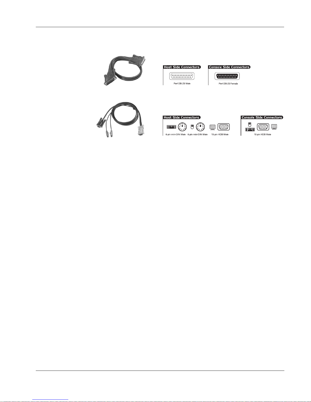
2L-1700 / 2L-1701
2L-5201P / 5202P / 5203P
Introduction
Note: 1. The ACS-1208AL/ACS-1216AL does not support serial
mice. You cannot use Serial-to-PS/2 adapters with th e
cables. Attempts to do so will not work.
2. If your computer uses an AT style keyboard socket you
will need to purchase a PS/2-to-AT keyboard adap ter (P art
No. 2A-106, or any standard keyboard adapter), in ord er to
plug the cable into the computer’s key board port.
1-5
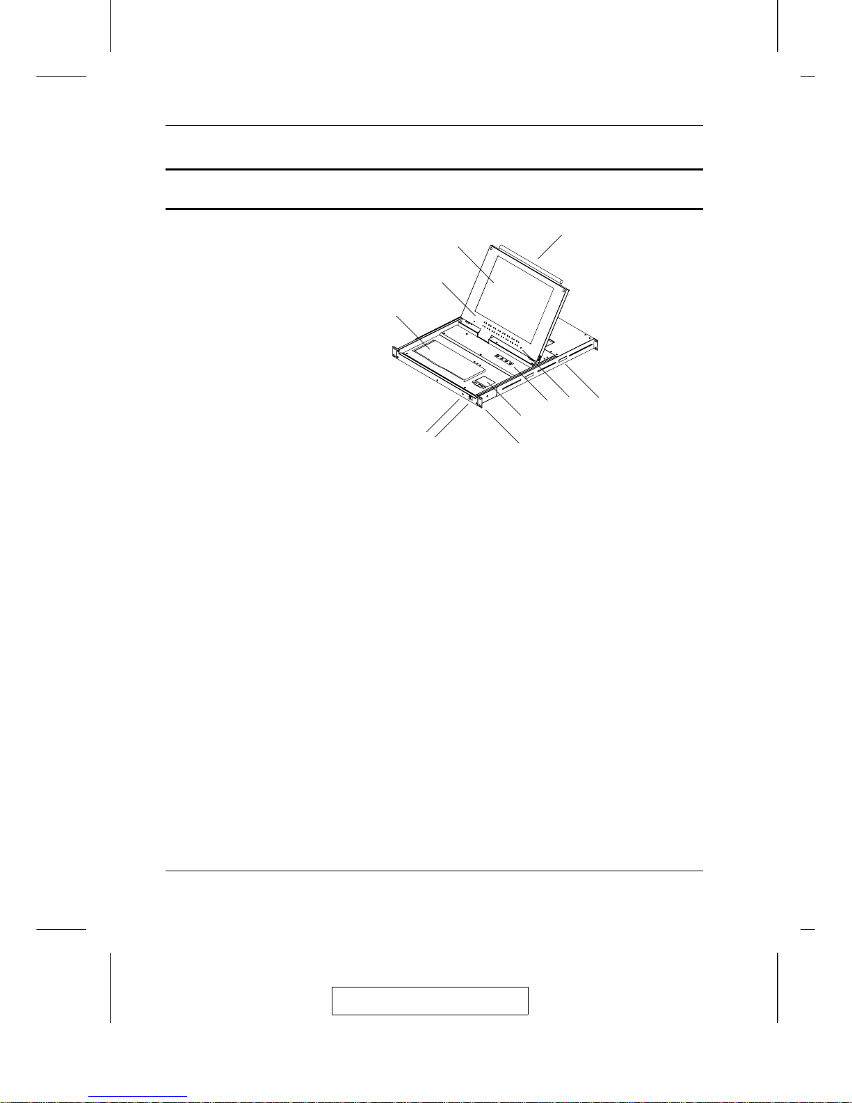
ACS-1208AL / ACS1216AL Front View
1. Handle
Pull to slide the KVM module out; push to slide the module in.
2. Cover
After sliding the KVM module out, flip up the cover to access the
LCD monitor, keyboard and touchpad.
3. Port LEDs
Port LEDs provide status information about their corresponding
CPU Ports. The top row of LEDs corresponds to Ports 1 - 8; the
bottom row corresponds to Ports 9 - 16. There are two LEDs for
each Port. The one on the left is the On Line LED; the one on the
right is the Selected Port LED:
M
An On Line LEDs light ORANGE to indicate that the
computer attached to the corresponding port is up and running.
M
A Selected LEDs light GREEN to indicate that the computer
attached to the corresponding port is the one that has the KVM
focus. The LED is steady under normal conditions, but flashes
when its port is accessed under Auto Scan Mode (see F7
SCAN, p. 4-14).
8
1
2
3
4
9
11
10
7
5
6
2005-01-05
ACS-1208AL / ACS-1216AL User Manual
1-6

Note: 1. Since the ACS-1208AL only has eight ports, only the
top row of LEDs (corresponding to Ports 1 - 8) are
active on that unit.
2. When the ACS-1208AL / ACS-1216AL is first
powered on, the On Line and Selected LEDs blink
one after the other as the Switch performs a self-test.
4. Keyboard
5. Power LED
6. Slide Release
The ACS-1208AL / ACS-1216AL has a mechanism that locks it
in the “In” position to prevent it from accidentally sliding out. To
slide the the console out, release it by moving this tab sid eway s.
7. Rack Mounting Brackets
There are rack mounting brackets attached to each corner of the
unit. Refer to Appendix C for rack mounting details.
8. Touchpad
9. LCD Display Controls
The LCD On/Off Switch is located here, as well as buttons to control
the position and picture settings of the LCD display. See the LCD
OSD Configuration section p. 1-10, for details.
10. Reset Switch
Press this recessed switch in with a thin object to perform a
system reset.
11. Slide Return Button
There is another slide return button on the opposite side of the
KVM module. Both buttons must be pressed to allow the module
to slide back in:
a) First slide the module completely out.
b) Press both buttons to unlock the module.
c) Slide the module back in.
2005-01-05
Introduction
1-7
ACS-1208AL / ACS-1216AL User Manual
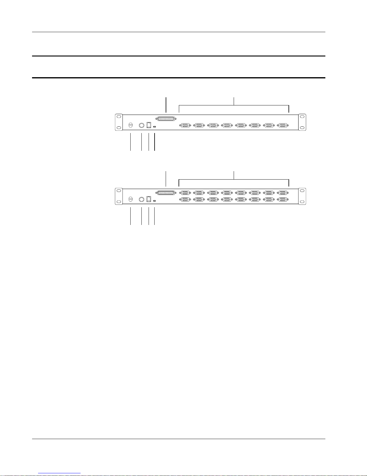
ACS-1208AL / ACS-1216AL Rear View
1
3
5
4
6
1
3
5
4
6
1. Daisy Chain Port
2
2
When Daisy Chaining Units, th e cab le plugs in here.
2. CPU Port Section
The cables that link to the computers plug in here.
Note: The shape of these 15-pin connectors has been specifically
modified so that only KVM cables designed to wo rk with
this switch can plug in (see the Cables section on p. 4, for
details). Do NOT attempt to use ordinary 15 pin VGA
connector cables to link these ports to the co mp uters.
3. Cable Tie Slot
If you want to use a cable tie to gather the cables together, you can
run it through this slot to attach it to the unit.
4. Power Jack
The power adapter cable plugs in here.
1-8

Introduction
5. Firmware Upgrade Port
The Firmware Upgrade Cable that transfers the firmware upgrade
data from the administrator’s computer to the ACS-1208AL /
ACS-1216AL (see p. 5-2), plugs into this RJ-11 connector.
6. Firmware Upgrade Recovery Switch
During normal operation and while performing a fimware
upgrade, this switch should be in the NORMAL position. See p.
5-7 for details about the use of this switch.
1-9

ACS-1208AL / ACS-1216AL User Manual
LCD OSD Configuration
The LCD OSD allows you to set up and configure the LCD display:
w To bring up the LCD OSD main menu, press the button marked Menu.
w Use the ▲ and ▼ buttons to navigate and make adjustmen ts with ;
after navigating to a setting choice, use the Menu button to bring
up the adjustment screen.
w When making adjustments, ▲ increases the value; ▼ decreases
the value.
w When you are satisfied with your adjustment, press Exit to return
to the OSD main menu.
w When all your adjustments have been made, press Exit to close the
LCD OSD.
An explanation of the settings is given in th e tab le belo w:
Auto Adjust Automatically configures all the settings for the LCD panel to
what the OSD considers the optimum values
Brightness Adjusts the background black level of the screen image.
Contrast Adjusts the foreground white level of the screen image.
Phase Adjusts the vertical size of the screen image.
Clock Adjusts the horizontal size of the screen image.
H-Position Positions the display area on the LCD panel horizontally
(moves the display area left or right).
V-Position Positions the display area on the LCD panel vertically (moves
the display area up or down).
Color Adjustment Adjusts the color quality of the display. You can adjust the
“warmth” value, color balance, etc. The Adjust Color selection
has a further submenu that lets you fine tune the RGB values.
Language Selects the language that the OSD displays its menus in.
Recall Resets the adjustments on all menus and submenus to their
factory default settings.
1-10

his chapter explains how to connect up your installation — from a basic single
T
stage hookup to a complete daisy chained setup.
Before you Begin
1. Make sure that power to all the devices you will be connecting up
have been turned off.
2. To prevent damage to your equipment due to ground potential
difference, make sure that all devices on the installation are
properly grounded. Consult your dealer for technical details, if
necessary.
Chapter 2.
Installation
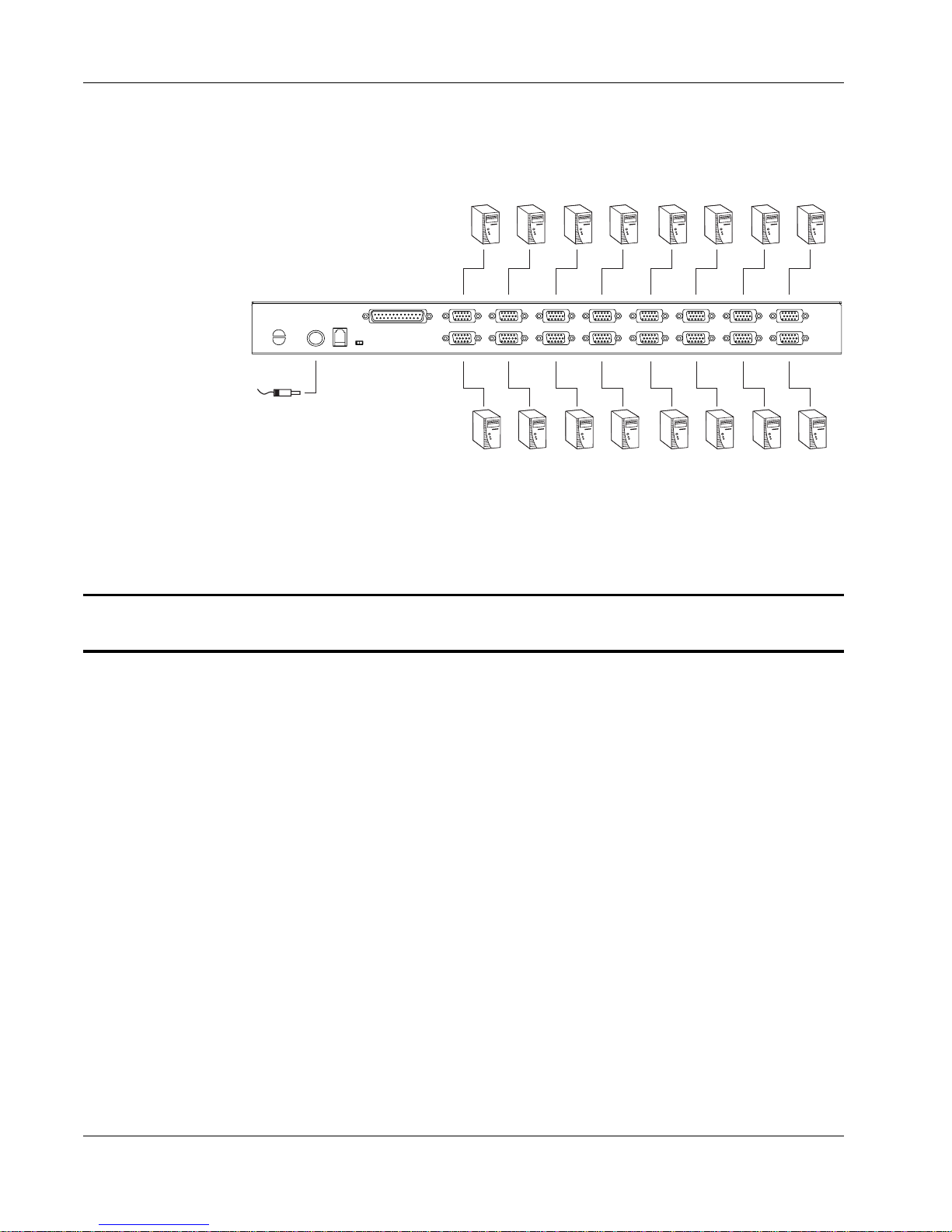
Single Stage Installation
In a Single Stage installation, there are no additional switches daisy
chained down from the first unit. To set up a sin gle stage installation do
the following:
1. Use KVM cable sets (as described in the Cables section on p.
1-4), to connect any available CPU Port to the Keyboard, Video
and Mouse ports of the computer you are installing.
Note: Ignore the Daisy Chain Port at this time. It is only used
when daisy chaining additional Master View units. Daisy
chaining is described in the next section.
2. Plug the power adapter cable into the Master View’s Power Jack,
then plug the power adapter into an AC power so urce.
2-1
ACS-1208AL / ACS-1216AL User Manual
3. Turn on the power to the computers.
Daisy Chaining
To control even more computers, up to 31 additional Master View
ACS-1208A / ACS-1216A units can be daisy chained down from the
First Station.
Note: It would be unnecessarily wasteful and expensive to use
As many as 256 (ACS-1208AL) or 512 (ACS-1216AL) computers can be
controlled from the unit’s integrated Slideaway console in a complete
installation. Tables showing the relation between the number of computers
and the number of Master View ACS-1208A / ACS-1216A units needed
to control them are provided on p. A-1 in the Appendix.
ACS-1208AL / ACS-1216AL switches for daisy chaining
since there is no point in having consoles on the ch ain ed
switches. Therefore, ACS-1208A and ACS-1216A switches
are used, instead. These are similar in all respects to the
ACS-1208AL and ACS-1216AL, except that they come in
standard housings without the built in Slideawayconsole.
2-2

Installation
To set up a daisy chained installation, do the followin g:
1. Make sure that power to all the devices you will be connecting up
has been turned off.
2. Use a daisy chain cable set (described in the Cables section, p.
1-4), to connect the Chain Ou t port of th e parent unit to the Chain
In port of the child unit (First Station Out to Seco nd Statio n In ,
Second Station Out to Third Station In, etc.).
3. Use KVM cable sets (described in the Cables section, p. 1-4), to
connect any available CPU Port to the Keyboard, Video and
Mouse ports of the computers you are installing.
4. Repeat the above steps for any additional Master View units you
wish to add to the chain.
5. Power up the installation according to the following procedure:
a) Plug in the power adapter for the First Station.
Wait a few seconds for the unit to ascertain its Station ID.
b) Plug in the power adapters for each Station on th e in stallatio n
in turn (Second Station, then Third Statio n, etc. ).
Each ACS-1208A / ACS-1216A has a LED display on its front
panel to indicate its Station ID (the Station ID for the First Stage
unit is 01, the ID for the Second Stage unit is 02, the ID for the
Third Stage unit is 03, etc.).
In each case, wait for the Station ID to be ascertained and
displayed on the Station ID LED before plugging in the next
Station.
c) After all the Stations are up, power on the computers.
2-3
 Loading...