

Page 1
Optional Rack Mount Kits Installation Guide
Introduction
For LCD KVM Switches/Consoles, ATEN provides a variety of optional rack mounting options to provide:
1) Flexibility
A long-railed version of your standard mounting kit lets you fit your device to racks with greater depth.
2) Convenience
Easy Installation Rack Mount Kits are designed to be easy to install and can be installed by one person.
Standard Installation Rack Mount Kit (Long)
Package Contents
1 x Standard Installation Rack Long Rail Set (2X-010G/2X-023G/2X-040G)
Compatible LCD KVM Units
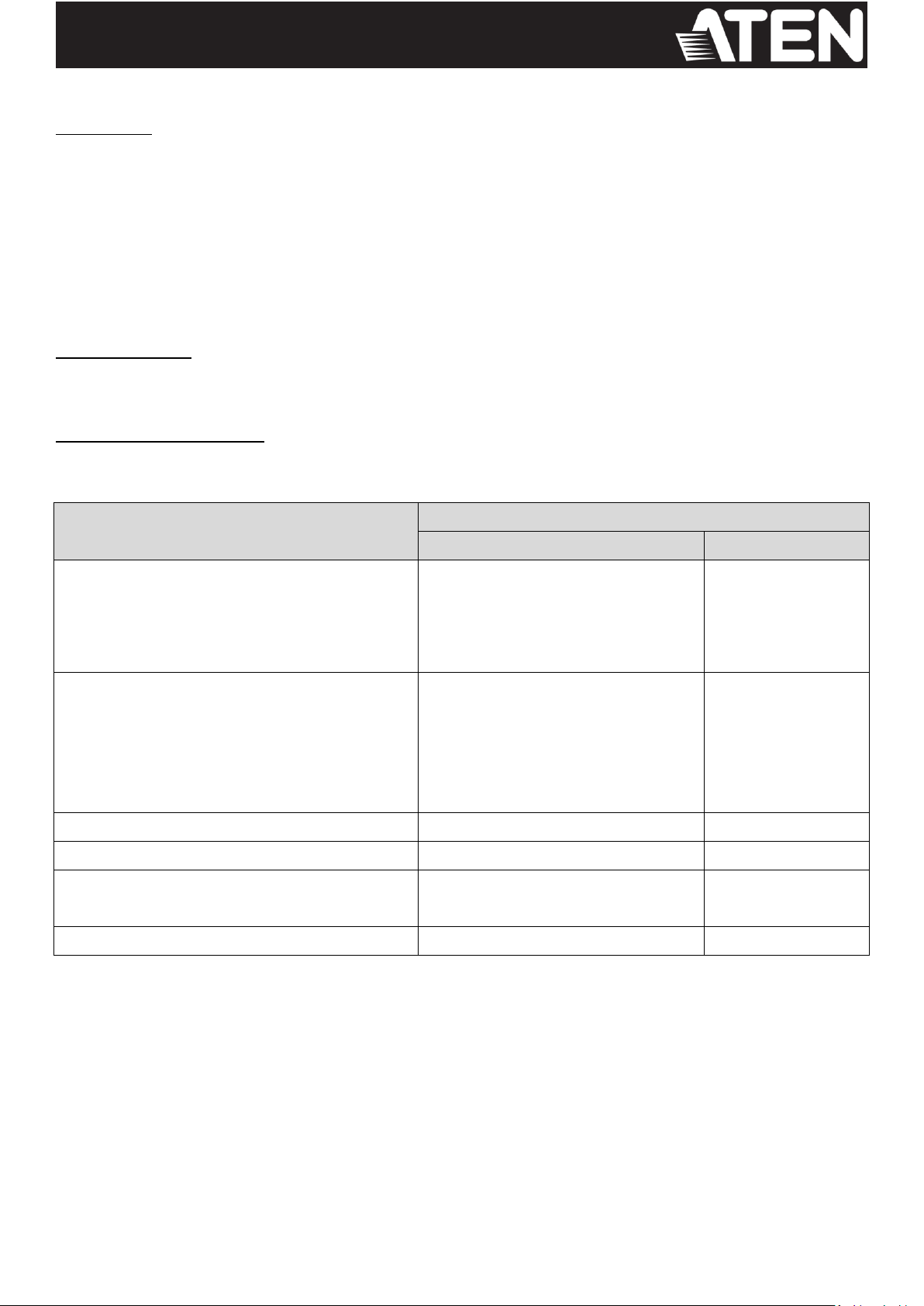
Refer to the table below for the compatible mounting kit and the rack depth for different LCD KVM
Switches/Consoles.
LCD KVM Switch / LCD Console Model
Standard Installation Rack Mount Kit (Long)
Compatible Subtype
Rack Depth (cm)
CL3000N,
CL5708N, CL5716N, CL5708IN, CL5716IN,
CL5800N, CL5808N, CL5816N,
CL6700MW, CL6708MW
Standard Installation – Long (2X-010G)
70–105
CL1008M, CL1016M,
CL5708M, CL5716M, CL5708IM, CL5716IM,
KL1108VN, KL1116VN,
KL1508AN, KL1516AN, KL1508AiN, KL1516AiN,
KL1508AM, KL1516AM, KL1508AiM, KL1516AiM
Standard Installation – Long (2X-010G)
68–105
CL1000M
Standard Installation – Long (2X-010G)
68–100
CL1000N, CL1308N, CL1316N
Standard Installation – Long (2X-023G)
70–105
CL3108NX, CL3116NX,
CL3884NW
Standard Installation – Long (2X-040G)
70–105
CL3100, CL3700, CL3800
Standard Installation – Long (2X-040G)
70–100
Note:
- It takes two people to mount the console.
- The standard rack mounting kit does not include screws or cage nuts. If you need additional screws or cage nuts,
contact your rack dealer.
All information, documentation and specifications contained in this media are subject to change without prior notification by the manufacturer.
Please visit our website to find the most up-to-date version.
1
Page 2

Components – 2X-010G and 2X-023G
Hardware Installation – 2X-010G and 2X-023G
Since installation for 2X-010G and 2X-023G mounting kits and the corresponding LCD KVM switches / LCD consoles
are the same, one combination will be used as the example instructions below.
1. Have one person position the unit in the rack and hold it steady. Have the second person screw the front
brackets to the rack.
All information, documentation and specifications contained in this media are subject to change without prior notification by the manufacturer.
Please visit our website to find the most up-to-date version.
2
Page 3

2. While the first person still holds the unit in place, the second person slides the left and right L-shaped brackets
into the unit’s side mounting brackets from the rear, installing four screws in the tabs to secure them in place.
3. After the L-shaped brackets are secured, tighten all the screws.
Allow at least 5.1 cm on each side for proper ventilation, and at least 12.7 cm at the back for the power cord
and cable clearance.
Components – 2X-040G
All information, documentation and specifications contained in this media are subject to change without prior notification by the manufacturer.
Please visit our website to find the most up-to-date version.
3
Page 4

Hardware Installation – 2X-040G
Since installation for 2X-040G mounting kit and the corresponding LCD KVM switches / LCD consoles are the same,
one combination will be used as the example instructions below.
1. Attach the left and right L-shaped brackets to the back of the rack, installing four screws in the tabs to secure
them in place.
2. While one person inserts the unit into place by sliding its left and right side bars into the left and right L-shaped
brackets (on the rack), have a second person screw the front brackets to the rack.
3. After the front brackets are secured, tighten all the screws.
Allow at least 5.1 cm on each side for proper ventilation, and at least 12.7 cm at the back for the power cord
and cable clearance.
All information, documentation and specifications contained in this media are subject to change without prior notification by the manufacturer.
Please visit our website to find the most up-to-date version.
4
Page 5

Easy Installation Rack Mount Kits – 2K-0003/2K-0004, 2K-0005/2K-0006
Package Contents
1 x Easy Installation Rack Rail Set – Short (2K-0003/2K-0005) or Long (2K-0004/2K-0006)
1 x M4*6 Type I Screw Set (4 screws)
Compatible LCD KVM units
Refer to the table below for the compatible mounting kit and the rack depth for different LCD KVM
Switches/Consoles.
LCD KVM Switch / LCD Console Model
Easy Installation Rack Mount Kit
Compatible Subtype
Rack Depth (cm)
CL1000M, CL1000N,
CL3000N
Easy Installation – Short (2K-0003)
57–70
Easy Installation – Long (2K-0004)
68–105
CL3100, CL3700
Easy Installation – Short (2K-0003)
42.5–70
Easy Installation – Long (2K-0004)
68–105
CL3800
Easy Installation – Short (2K-0003)
46.5–70
Easy Installation – Long (2K-0004)
68–105
CL1008M, CL1016M,
CL1308N, CL1316N,
CL3108NX, CL3116NX, CL3884NW,
CL5708N, CL5716N, CL5708IN, CL5716IN,
CL5708M, CL5716M, CL5708IM, CL5716IM,
CL5800N, CL5808N, CL5816N,
CL6700MW, CL6708MW
Easy Installation – Short (2K-0005)
57–70
Easy Installation – Long (2K-0006)
68–105
KL1108VN, KL1116VN,
KL1508AN, KL1516AN, KL1508AiN, KL1516AiN,
KL1508AM, KL1516AM, KL1508AiM, KL1516AiM
Easy Installation – Short (2K-0005)
57–70
Easy Installation – Long (2K-0006)
68–105
Components
An “L” should be etched on the left rail and an “R” is etched on the right rail.
All information, documentation and specifications contained in this media are subject to change without prior notification by the manufacturer.
Please visit our website to find the most up-to-date version.
5
Page 6

Hardware Installation
Since installation for all four mounting kits and the corresponding LCD KVM switches / LCD consoles are the same,
one combination will be used as the example instructions below.
1. Remove all packing materials (paper wrap, plastic wrap, etc.).
2. Align the mount kit rails to the rack and stabilize them to the rack by screwing rack screws to the front and rear
flanges as shown:
3. Place the LCD unit onto the rails’ support flanges, push it inward and stabilize it by screwing an M4*6 Type I
Screw to each of the unit’s rack mounting brackets as shown:
All information, documentation and specifications contained in this media are subject to change without prior notification by the manufacturer.
Please visit our website to find the most up-to-date version.
6
Page 7

4. Stabilize the LCD unit further by screwing an M4*6 Type I Screw to each of the unit’s rear attachment sliding
brackets.
The installation is complete.
All information, documentation and specifications contained in this media are subject to change without prior notification by the manufacturer.
Please visit our website to find the most up-to-date version.
7
 Loading...