

Page 1
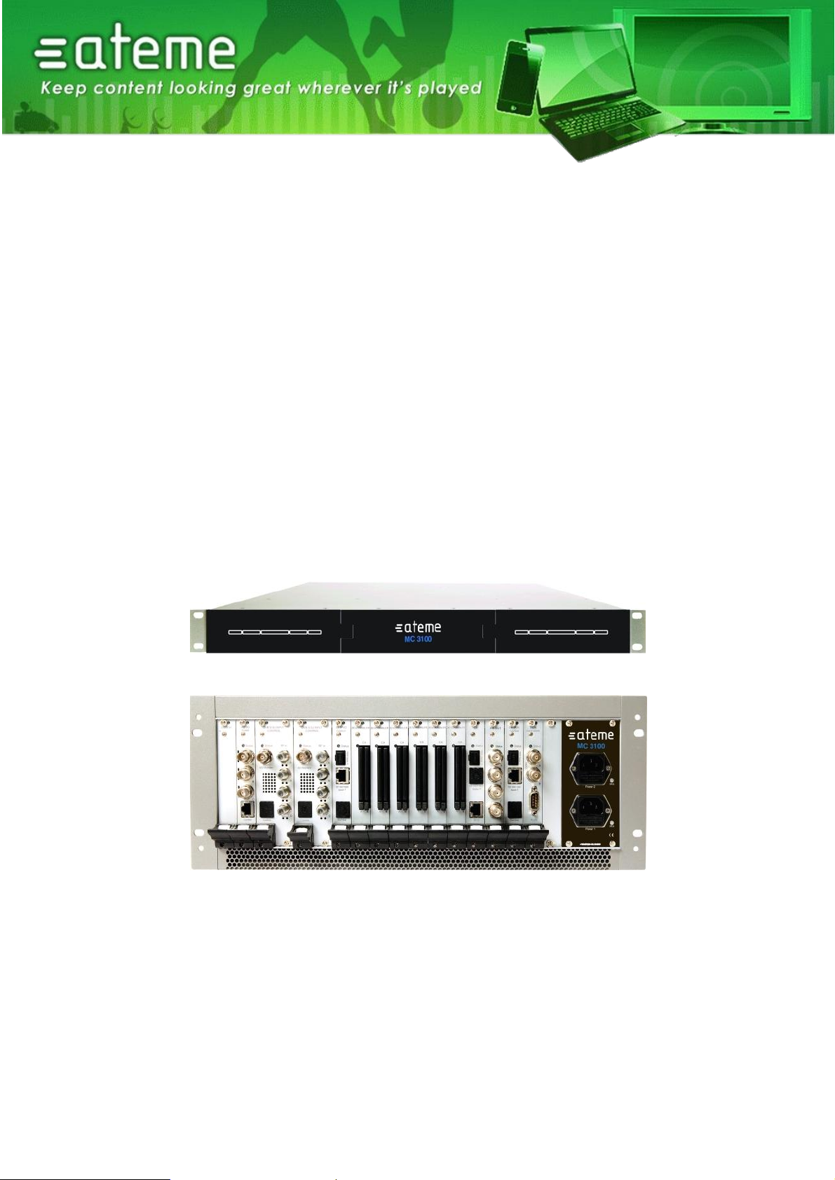
MC3x00 Multiplexer & Gateway
User Manual – v3.8
Document identification
MC3x00-UM-v3.8
www.ateme.com 26 Burospace – Route de Gisy – 91570 Bièvres – France
Page 2
MC3x00 – User Manual
Document
Version
Date
Evolution description
2.14
2010
V2.14 Release
2.16
Nov 9th, 2011
V2.16 Release
Document template update
3.2
March 2012
V302 Release
3.4
August 2012
V3.4 Release
3.6
December 2012
V3.6 Release
3.8
March 2013
V3.8 Release
Summary of changes
Page 2 / 213
Page 3

MC3x00 – User Manual
Contents
1 INTRODUCTION 12
2 INSTALLATION AND SAFETY 13
2.1 THE 4RU CHASSIS .................................................................................................... 13
2.1.1 Ventilation 13
2.1.2 Replacing the power supply module 13
2.2 THE 1RU CHASSIS .................................................................................................... 14
2.2.1 Ventilation 14
2.2.2 Replacing the power supply module 14
2.3 SAFETY CONSIDERATIONS ......................................................................................... 14
2.4 INSTALLATION ........................................................................................................... 15
2.4.1 Power supply rating 15
2.4.2 4RU chassis with 300 and 400W AC Power 15
2.4.3
Page 3 / 213
Page 4

MC3x00 – User Manual
4 ADMINISTRATIVE SETTINGS CONFIGURATION 25
4.1 ACCESSING THE WEB INTERFACE ............................................................................... 25
4.1.1 Assigning an IP Address 26
4.1.2 IPv6 Address Support 28
4.1.3 Management GUI 28
4.1.4 Management over IP-Data Port and VLANs 30
4.1.5 Internal Time Clock Setting / Network Time Protocol (NTP) Server 31
4.1.6 Password Protection in the GUI 32
4.1.7 Changing the Password for the GUI 32
4.1.8 Optional Languages 33
4.2 CONFIGURATION OF CLOCK REFERENCE MODULE ........................................................ 34
4.2.1 Configuration 34
4.3 LICENSING ................................................................................................................ 36
4.3.1 Ordering a License File 38
4.3.2 Installing a License File 38
5 INPUT CONFIGURATION 39
5.1 THE INPUTS NODE ..................................................................................................... 39
5.2 INPUT ANALYSIS ........................................................................................................ 40
5.2.1 Input Port Analysis 41
5.2.2 Input Service Filtering and Analysis 41
5.2.3 Input PID Analysis 43
5.3 MANUAL PSI ............................................................................................................. 45
5.3.1 MPTS Support 46
5.3.2 PSI Modifications of input services 47
5.3.3 Defining a component type for an incoming PID. 47
5.3.4 Changing the language descriptor of an incoming audio 48
5.3.5 Edit options on existing manual PSI 49
5.4 DVB-S/S2 INPUT ...................................................................................................... 49
5.5 ASI INPUT ................................................................................................................. 53
5.6 QAM/DVB-C INPUT .................................................................................................. 55
5.7 COFDM/ DVB-T INPUT ............................................................................................. 58
5.8 IP INPUT ................................................................................................................... 61
5.8.1 Setup of IPv6 input 63
5.8.2 IGMP Source filtering on Switch IP input. 64
5.8.3 IP Input with FEC 65
5.8.4 Adding a New Input Stream 66
5.8.5 Removing a Multicast Input 66
5.8.6 IP Input seamless switching module 67
5.9 8VSB INPUT ............................................................................................................. 69
5.10 QAM-B INPUT ........................................................................................................... 71
5.11 DVB-T2 INPUT .......................................................................................................... 73
6 CONDITIONAL ACCESS CONFIGURATION 77
6.1 DESCRAMBLING – COMMON INTERFACE MODULE ........................................................ 77
6.1.1 Descrambling a Service 78
6.1.2 Transporting a Descrambled Service to Multiple Output Modules/Ports 78
6.1.3 CAM Configuration 78
6.1.4 Alt CAM Mode 81
6.1.5 CAM Interface 81
Page 4 / 213
Page 5

MC3x00 – User Manual
6.1.6 Navigation 81
6.1.7 Multiple Users and CAM access 82
6.1.8 Error Handling 83
6.2 BULK DESCRAMBLING ................................................................................................ 84
6.2.1 Verimatrix Configuration 85
6.2.2 BISS Scrambling and Descrambling 87
6.3 SCRAMBLING ............................................................................................................ 89
6.3.1 Scrambler Module Configuration 90
7 DECODER OUTPUT CONFIGURATION 99
7.1 CHANNEL CONFIGURATION ........................................................................................ 99
7.1.1 Decoder Status 101
7.1.2 Decoder Parameter Configuration 104
7.1.3 Dolby® Digital Plus Professional Decoder 109
7.1.4 VBI/Test lines (or VBI/VANC/Test lines) 113
7.1.5 Descrambling for the Decoder Module 114
7.1.6 Upconverter: RF Parameter Configuration 114
7.1.7 Semi-agile frequency setting 114
7.1.8 Video Sync Shutoff 116
7.1.9 RF/NICAM or RF/A2 Parameter Configuration 117
7.1.10 TVMOD- PAL/SECAM switching in Decoders 118
7.1.11 Carrier offset in TVMOD 118
7.2 GENLOCK FEATURE ................................................................................................. 119
7.3 ON SCREEN DISPLAY MESSAGING (OSDM) .............................................................. 120
7.3.1 Enabling OSD Messaging 121
7.3.2 Disabling OSD Messages 121
8 DIGITAL OUTPUT CONFIGURATION 122
8.1 INPUT STREAM SELECTION ...................................................................................... 123
8.2 AUTO SERVICE MODES ............................................................................................ 124
8.2.1 Configuring an output with Auto All Services 124
8.3 TRANSPORT STREAM GENERATION .......................................................................... 125
8.3.1 Transport Settings 129
8.3.2 Port Settings 130
8.3.3 EMM 130
8.3.4 PSI 132
8.3.5 EPG 132
8.3.6 Service 133
8.3.7 Components 134
8.3.8 Manual Mapping 135
8.3.9 Scrambling 138
8.4 OUTPUT PORT SETTINGS ......................................................................................... 140
8.4.1 IP Output module 140
8.4.2 ASI Output Module 143
8.4.3 QAM Output Module 145
8.4.4 COFDM Output Module 146
8.4.5 DVB-S/S2 Output Module 147
8.4.6 DVB-T2 Output Module 150
8.5 OUTPUT OPTIONS ................................................................................................... 151
8.5.1 Virtual MPTS Output 151
8.5.2 MPTS Transparent Mode 151
Page 5 / 213
Page 6

MC3x00 – User Manual
8.5.3 MPTS Semi-Transparent Mode 152
8.6 PSI/PSIP CONFIGURATION ...................................................................................... 153
8.6.1 Editing the PSI Network configuration 154
8.6.2 Editing the PSI Default Values 155
8.6.3 Editing the Logical Chanel Descriptor (NIT) 156
8.6.4 Editing the BAT table 158
8.6.5 Editing the TOT Local Time Offset Descriptor 158
8.6.6 PSI Synchronization 160
8.6.7 Inserting Generic Descriptors 161
8.6.8 Modifying PSI Generation Settings 163
8.6.9 DVB ATSC, ATSC DVB Conversion 165
8.6.10 SI Domain Support 165
9 FM RADIO OUTPUT CONFIGURATION 167
9.1 CONFIGURING GLOBAL PARAMETERS FOR A MODULE ................................................ 167
9.2 CONFIGURING RADIO SERVICES ............................................................................... 168
9.3 CONFIGURING RDS OUTPUT .................................................................................... 170
9.3.1 Manual RDS 171
9.3.2 Ancillary and Auxiliary RDS 171
9.3.3 Dynamic Looping 173
9.3.4 Stereo override 173
10 DIGITAL PROCESSING MODULES 174
10.1 AUDIO LEVELING MODULE ....................................................................................... 174
10.2 ELECTRONIC PROGRAM GUIDE (EPG) ...................................................................... 175
10.2.1 EPG Status 175
10.2.2 Setting up EPG 176
10.3 ADDING EPG INFORMATION TO A TRANSPORT STREAM ............................................. 178
10.3.1 Playout Rate, Playout Limit, and Priority 179
10.3.2 EIT Source Setup 181
11 REDUNDANCY SUPPORT 182
11.1 INPUT REDUNDANCY................................................................................................ 182
11.1.1 Configuring Service-based Input Redundancy 183
11.1.2 Configuring Port-based Input Redundancy 183
11.1.3 Alarms that cause Switching 185
11.1.4 Input Redundancy and the MMI 185
11.2 INTERNAL REDUNDANCY .......................................................................................... 185
11.2.1 Dual backplane configuration 186
11.2.2 Hardware Requirements 186
11.2.3 Configuring Modules for Internal Redundancy 187
11.2.4 Decoder Internal Redundancy 189
11.2.5 QAM/COFDM/IP/ASI Output Internal Redundancy 190
11.2.6 FM Radio Internal Redundancy 190
11.3 CA REDUNDANCY ................................................................................................... 191
11.3.1 ECMG Redundancy 191
11.3.2 Redundancy Configuration 192
11.3.3 Manual Switching 192
11.3.4 EMMG Redundancy 193
11.4 IP OUTPUT REDUNDANCY ........................................................................................ 193
11.4.1 Multicast Configuration 194
Page 6 / 213
Page 7

MC3x00 – User Manual
11.4.2 OSPF Configuration 194
11.4.3 Defining the Source Subnet 194
11.4.4 Defining the Source IP Address 196
11.4.5 Mute on Error 197
12 CONTROL AND MONITORING 198
12.1 SYSTEM STATUS ..................................................................................................... 198
12.1.1 Service View 198
12.1.2 Output View 200
12.1.3 Hardware View 201
12.1.4 Active Alarms 202
12.1.5 Alarm History 203
12.1.6 Alarm Setup 204
12.1.7 Root Cause Filter 205
12.2 SNMP .................................................................................................................... 205
12.2.1 Configuration of SNMP Alarm Filter via the GUI 205
12.2.2 Configuration of SNMP Trap Destination Table via the GUI 205
12.2.3 Configuration of Trap Destination Table via SNMP 205
12.2.4 Interpretation of Traps 206
12.3 SOAP XML INTERFACE ........................................................................................... 206
13 MAINTENANCE 207
13.1 SOFTWARE UPGRADES ............................................................................................ 207
13.2 HOT-SWAPPING ...................................................................................................... 207
13.2.1 Performing a Hot-Swap 207
13.2.2 Switch+MMI Module Hot-swap 207
13.2.3 Other Module Hot-swap 208
13.3 ADDING, REPLACING, OR REMOVING MODULES ......................................................... 208
13.4 IMPORTING AND EXPORTING CHASSIS CONFIGURATION ................................ ............. 210
13.5 RESTORING THE DEFAULT IP ADDRESS .................................................................... 211
14 SUPPORT AND CONTACT INFORMATION 212
A. NOTICES 213
Page 7 / 213
Page 8

MC3x00 – User Manual
Table of Figures
Figure 1 – 4RU chassis with power connectors, switch module and available slots. ......................................................... 13
Figure 2 – 1RU chassis with power connector, switch module and available slots; front and rear view. ............................ 14
Figure 3 – Power Input for 4RU chassis with 300 and 400 Watt AC power ....................................................................... 15
Figure 4 – Front plate of dual 48V Power Supply in a MC3000 ......................................................................................... 16
Figure 5 – Layout of 48V DC Power Supply Connector ................................................................................................ .... 16
Figure 6 – Power Input Connector for 1RU Chassis ......................................................................................................... 16
Figure 7 – Classification label ........................................................................................................................................... 18
Figure 8 – CDRH identification label ................................................................................................................................ . 18
Figure 9 – QAM Modulator ............................................................................................................................................... 22
Figure 10 – Two-Slot Wide Quad Decoder ................................................................ ....................................................... 24
Figure 11 – Three-Slot Wide Quad Decoder..................................................................................................................... 24
Figure 12 – Web Home Page ........................................................................................................................................... 25
Figure 13 – Admin View ................................................................................................................................................... 26
Figure 14 – Admin Properties View .................................................................................................................................. 26
Figure 15 – Setting up Virtual LANs ................................................................................................................................. 27
Figure 16 – IPv6 Address in Admin Page ......................................................................................................................... 28
Figure 17 – Manual IPv6 Address ................................................................................................................................ .... 29
Figure 18 – IPv6 Internal Redundancy ............................................................................................................................. 29
Figure 19 – IPv6 PSI Synchronization .............................................................................................................................. 29
Figure 20 – Setting up Virtual LANs ................................................................................................................................. 30
Figure 21 – Setting up Virtual LANs via Management port ............................................................................................... 31
Figure 22 – Setting the Time and Date ............................................................................................................................. 32
Figure 23 – Login Management Section ........................................................................................................................... 32
Figure 24 – Password Configuration ................................................................................................................................ 32
Figure 25 – Changing the Password ................................................................................................................................ 33
Figure 26 – Optional Languages ...................................................................................................................................... 33
Figure 27 – Clock reference module. ................................................................................................................................ 34
Figure 28 – Configuration of clock reference module ........................................................................................................ 34
Figure 29 – Parameters of clock reference module .......................................................................................................... 35
Figure 30 – MMI Clock Reference selection ..................................................................................................................... 36
Figure 31 – MMI Clock Reference warning ....................................................................................................................... 36
Figure 32 – Licensing ....................................................................................................................................................... 38
Figure 33 – Inputs Node ................................................................................................................................................... 39
Figure 34 – Example of DVB-S/S2 Inputs ......................................................................................................................... 40
Figure 35 – DVB-S/S2 Port Detailed View ........................................................................................................................ 41
Figure 36 – Detailed PSI/SI Analysis of Input Services ..................................................................................................... 42
Figure 37 – PID Scrambled with Even Control Word ........................................................................................................ 43
Figure 38 – PID Scrambled with Odd Control Word .......................................................................................................... 43
Figure 39 – Selecting PID 20 ............................................................................................................................................ 44
Figure 40 – Selecting PID 550 .......................................................................................................................................... 44
Figure 41 – Manually define Input PSI .............................................................................................................................. 45
Figure 42 – Table Analysis when an Input Service is defined ........................................................................................... 46
Figure 43 – Verifying manually defined Inputs .................................................................................................................. 46
Figure 44 – Defining Manual PSI ...................................................................................................................................... 47
Figure 45 – Defining component for service ..................................................................................................................... 47
Figure 46 – Edit Language descriptor ............................................................................................................................... 48
Figure 47 – Editing existing Manual PSI ........................................................................................................................... 49
Figure 48 – DVB-S2 Input ................................................................................................................................................ 50
Figure 49 – Edit DVB-S/S2 Port Configuration ................................................................................................................. 51
Figure 50 – Edit DVB-S/S2 (HW Rev. 2.0) Port Configuration ................................ .......................................................... 51
Figure 51 – DVB-S/S2 Status View .................................................................................................................................. 52
Figure 52 – ASI Input ....................................................................................................................................................... 53
Figure 53 – ASI Edit Dialog .............................................................................................................................................. 53
Figure 54 – ASI Status View............................................................................................................................................. 54
Figure 55 – QAM Input ..................................................................................................................................................... 55
Figure 56 – QAM Edit Dialog ............................................................................................................................................ 56
Figure 57 – QAM Status View'.......................................................................................................................................... 56
Figure 58 – COFDM Input ................................................................................................................................................ 58
Figure 59 – COFDM Edit Dialog ....................................................................................................................................... 59
Figure 60 – COFDM Status View ..................................................................................................................................... 59
Figure 61 – IP Input .......................................................................................................................................................... 61
Figure 62 – Edit IP Port .................................................................................................................................................... 62
Figure 63 – IP Input Port Status ....................................................................................................................................... 63
Figure 64 – Setup of IPv6 input ........................................................................................................................................ 64
Figure 65 – Edit IP Port for IGMP source filtering ............................................................................................................. 65
Figure 66 – IP Input Page (for Modules with FEC) ............................................................................................................ 65
Figure 67 – IP Input Port Status (for Modules with FEC) .................................................................................................. 66
Figure 68 – IP Input Seamless module Status Parameter view ........................................................................................ 68
Figure 69 – IP Input Seamless module Status Parameter detailed view. .......................................................................... 68
Figure 70 – 8VSB Input .................................................................................................................................................... 69
Figure 71 – 8VSB Status View ......................................................................................................................................... 70
Page 8 / 213
Page 9

MC3x00 – User Manual
Figure 72 – QAM-B Input ................................................................................................................................................. 71
Figure 73 – QAM-B Status View ....................................................................................................................................... 72
Figure 74 – DVB-T2 Input ................................................................................................................................................ 73
Figure 75 – DVB-T/ Input Port Configuration .................................................................................................................... 74
Figure 76 – DVB-T Status Parameter view ....................................................................................................................... 75
Figure 77 – DVB-T2 Status Parameter view ..................................................................................................................... 76
Figure 78 – Conditional Access Node............................................................................................................................... 77
Figure 79 – CAM Configuration within the Service Properties Dialog ................................................................................ 78
Figure 80 – CAM Configuration Page ............................................................................................................................... 79
Figure 81 – CAM Configuration Page (for chassis with a Quad Decoder) ......................................................................... 79
Figure 82 – Example of a Menu from Conax .................................................................................................................... 82
Figure 83 – Example of List from CryptoWorks ................................................................................................................ 82
Figure 84 – Example of Enquiry ....................................................................................................................................... 82
Figure 85 – Setting up the Bulk Descrambler Module ....................................................................................................... 84
Figure 86 – Configuring Verimatrix Parameters ................................................................................................................ 85
Figure 87 – Additional VKS Parameters ........................................................................................................................... 86
Figure 88 – Creating a BISS Mode 1 Key ......................................................................................................................... 87
Figure 89 – Setting up a BISS Scrambling Service ........................................................................................................... 88
Figure 90 – Setting up a BISS Descrambling Service ....................................................................................................... 88
Figure 91 – Scrambler Module Architecture...................................................................................................................... 89
Figure 92 – Scramblers Overview ................................................................ .................................................................... 90
Figure 93 – Adding an ECM Generator ............................................................................................................................ 91
Figure 94 – Editing ECMGs .............................................................................................................................................. 91
Figure 95 – Adding an ECM ............................................................................................................................................. 92
Figure 96 – Editing an existing ECM ................................................................................................................................ 93
Figure 97 – Adding an EMM Generator ............................................................................................................................ 94
Figure 98 – Editing an EMM Generator ............................................................................................................................ 95
Figure 99 – Adding an EMM/PD ....................................................................................................................................... 95
Figure 100 – Edit an existing EMM/PD ............................................................................................................................. 96
Figure 101 – Adding an EIS ................................................................................................ ............................................. 97
Figure 102 – Edit an EIS service ...................................................................................................................................... 98
Figure 103 – Decoders Node ........................................................................................................................................... 99
Figure 104 – Decoder Status Dialog ............................................................................................................................... 101
Figure 105 – MPEG-2/4 SD/HD Quad RF Decoder Configuration .................................................................................. 104
Figure 106 – MPEG-2/4 SD/HD SDI Decoder Configuration ........................................................................................... 104
Figure 107 – Illustration of the Video Aspect Ratio Conversion Parameter ..................................................................... 105
Figure 108 – CC Burn-in parameter ............................................................................................................................... 109
Figure 109 – Decoders with Dolby® Digital Plus option .................................................................................................. 110
Figure 110 – Decoders with Dolby® Digital Plus option .................................................................................................. 111
Figure 111 – Manual Channel spacing ........................................................................................................................... 115
Figure 112 – Adjacent RF Spacing under OIRT ............................................................................................................. 116
Figure 113 – TVMOD- PAL/SECAM Switching in decoders ............................................................................................ 118
Figure 114 – Carrier offset for TV MOD .......................................................................................................................... 119
Figure 115 – Genlock feature ......................................................................................................................................... 119
Figure 116 – Genlock offset feature ............................................................................................................................... 120
Figure 117 – Enable and Disable OSDM ........................................................................................................................ 120
Figure 118 – Outputs View ............................................................................................................................................. 122
Figure 119 – Dragging and Dropping a Service .............................................................................................................. 123
Figure 120 – Auto Service modes ................................................................................................................................ .. 124
Figure 121 – Auto All Services output configuration ....................................................................................................... 125
Figure 122 – Stopping a selected service ....................................................................................................................... 125
Figure 123 – Default Stream Properties for IP Modules .................................................................................................. 126
Figure 124 – Default Stream Properties for all other Modules ......................................................................................... 126
Figure 125 – Service Grouping ....................................................................................................................................... 127
Figure 126 – Layout of Properties Dialog for an MPTS ................................................................................................... 127
Figure 127 – Layout of Properties Dialog for an SPTS ................................................................................................... 128
Figure 128 – Transport Tab for ASI Modules .................................................................................................................. 129
Figure 129 – Delivery Descriptors for Cable ................................................................................................................... 129
Figure 130 – Delivery Descriptors for Satellite ................................................................................................................ 130
Figure 131 – Delivery Descriptors for Terrestrial............................................................................................................. 130
Figure 132 – Import TS PIDs .......................................................................................................................................... 130
Figure 133 – EMM Tab for IP Modules ........................................................................................................................... 131
Figure 134 – Passthrough Option for EMMs in SPTS ..................................................................................................... 131
Figure 135 – PSI Tab for IP Modules ............................................................................................................................. 132
Figure 136 – PSI Tab for a service encapsulated within an MPTS .................................................................................. 132
Figure 137 – EPG Tab for IP Modules ............................................................................................................................ 133
Figure 138 – Service Tab for IP SPTS............................................................................................................................ 133
Figure 139 – Components Tab for IP SPTS ................................................................................................................... 135
Figure 140 – Components multiplexing .......................................................................................................................... 137
Figure 141 – Scrambling Tab for IP SPTS ...................................................................................................................... 138
Figure 142 – Scrambling Tab for IP SPTS with BISS ..................................................................................................... 139
Figure 143 – Port Settings Tab for IP Modules ............................................................................................................... 140
Figure 144 – Forward Error Correction Panel for IP Modules ......................................................................................... 140
Figure 145 – Output Redundancy Panel for IP Modules ................................................................................................. 141
Figure 146 – Enabling CBR Mode .................................................................................................................................. 142
Figure 147 – Port Settings Tab for IP output modules with IPv6 ..................................................................................... 142
Page 9 / 213
Page 10

MC3x00 – User Manual
Figure 148 – Dragging and Dropping a Service with IPv6 Address ................................................................................. 143
Figure 149 – Port Settings Tab for ASI Modules ............................................................................................................. 143
Figure 150 – MIP Parameters for ASI Modules .............................................................................................................. 144
Figure 151 – Device Setup Node.................................................................................................................................... 145
Figure 152 – 16QAM Annex A/C Setup .......................................................................................................................... 145
Figure 153 – 16QAM Annex B Setup ............................................................................................................................. 146
Figure 154 – Port Settings Tab for COFDM Modules ..................................................................................................... 146
Figure 155 – DVB-S2 Output –Port Setting Configuration .............................................................................................. 147
Figure 156 – DVB-S2 Output –Linear Pre-correction ...................................................................................................... 149
Figure 157 – DVB-T2 Output –Port Setting Configuration ............................................................................................... 150
Figure 158 – Transport Tab for the Virtual QAM Output ................................................................................................. 151
Figure 159 – Port Settings Tab for the Virtual QAM Output ............................................................................................ 151
Figure 160 – Transparent Mode ..................................................................................................................................... 152
Figure 161 – Stream Properties for Semi-transparent MPTS .......................................................................................... 152
Figure 162 – PSI Networks ............................................................................................................................................ 154
Figure 163 – Edit PSI Networks ..................................................................................................................................... 155
Figure 164 – Associate transport stream with PSI network ............................................................................................. 155
Figure 165 – PSI Base Values tab (DVB Profile) ............................................................................................................ 155
Figure 166 – Edit NIT Settings ....................................................................................................................................... 156
Figure 167 – Edit NIT Settings with DigitalEuorpe having HD simulcast services ........................................................... 157
Figure 168 – Edit BAT Settings ...................................................................................................................................... 158
Figure 169 – TOT Settings Dialog .................................................................................................................................. 159
Figure 170 – PSI Synchronization Tab ........................................................................................................................... 160
Figure 171 – Generic Descriptor Tab ............................................................................................................................. 161
Figure 172 – Setup Tab.................................................................................................................................................. 163
Figure 173 – PSI Domains ............................................................................................................................................. 165
Figure 174 – FM Radio Page ......................................................................................................................................... 167
Figure 175 – FM Radio Settings Page ............................................................................................................................ 167
Figure 176 – Editing Channel Configuration ................................................................................................................... 169
Figure 177 – FM Radio Advanced Settings .................................................................................................................... 170
Figure 178 – Editing Channel Configuration (for RDS) ................................................................................................... 171
Figure 179 – Auxiliary RDS Configuration ...................................................................................................................... 172
Figure 180 – Advanced UECP Addressing Setup ................................................................................................ ........... 172
Figure 181 – Dynamic Looping ....................................................................................................................................... 173
Figure 182 – Stereo override in RDS menu .................................................................................................................... 173
Figure 183 – Audio Leveling Effect ................................................................................................................................. 174
Figure 184 – Setting up Audio Leveling .......................................................................................................................... 174
Figure 185 – EPG Node ................................................................................................................................................. 175
Figure 186 – EPG Status Node ...................................................................................................................................... 175
Figure 187 – EPG Setup ................................................................................................................................................ 176
Figure 188 – EPG Sync Peer Units ................................................................................................................................ 177
Figure 189 – Manually adding an EIT Source PID .......................................................................................................... 178
Figure 190 – Setting up EPG within the Outputs Node ................................................................................................... 178
Figure 191 – Setting a Playout Rate ............................................................................................................................... 179
Figure 192 – Setting a Playout Limit ............................................................................................................................... 180
Figure 193 – Setting a Priority ........................................................................................................................................ 180
Figure 194 – EPG Node ................................................................................................................................................. 181
Figure 195 – Input Redundancy Configuration ............................................................................................................... 182
Figure 196 – Configuring Service-based Input Redundancy ........................................................................................... 183
Figure 197 – Configuring Port-based Input Redundancy ................................................................................................ 184
Figure 198 – Redundancy Switching Triggers ................................................................................................................ 185
Figure 199 – Signal Flow within a Unit with Two Backplanes .......................................................................................... 186
Figure 200 – Internal Redundancy ................................................................ ................................................................ . 187
Figure 201 – Removing Inputs ....................................................................................................................................... 189
Figure 202 – Setting up ECMG redundancy ................................................................................................................... 192
Figure 203 – Setting up EMMG redundancy ................................................................................................................... 193
Figure 204 – Output Redundancy................................................................................................................................... 194
Figure 205 – Edit Redundancy Options .......................................................................................................................... 195
Figure 206 – Output Redundancy Port Settings ............................................................................................................. 196
Figure 207 – Service View ............................................................................................................................................. 198
Figure 208 – Service View Options ................................................................................................................................ 199
Figure 209 – Output View ............................................................................................................................................... 200
Figure 210 – Output View Options .................................................................................................................................. 201
Figure 211 – Hardware View .......................................................................................................................................... 201
Figure 212 – Active alarms ............................................................................................................................................. 202
Figure 213 – Example of IP Input Module with Status LED ............................................................................................. 203
Figure 214 – Alarm History ............................................................................................................................................. 203
Figure 215 – Registered Alarms ..................................................................................................................................... 205
Figure 216 – An alarm with specific alarm description .................................................................................................... 205
Figure 217 – Five Trap Destinations and the Alarm Filter can be set in the GUI. ............................................................ 205
Figure 218 – A Module with its Ejector released ............................................................................................................. 208
Figure 219 – Opening of Air Vents ................................................................ ................................................................ . 209
Figure 220 – Saving Importing and Exporting Chassis Configuration ............................................................................. 210
Figure 221 – Hardware IP reset DIP switch .................................................................................................................... 211
Page 10 / 213
Page 11

MC3x00 – User Manual
ASI
Asynchronous Serial Interface
CAM
Conditional Access Module
CI
Common Interface
COFDM
Coded Orthogonal Frequency Division Multiplexing
DDM
Dual Decoder Module
DVB
Digital Video Broadcasting
EBU
European Broadcasting Union
ECM
Entitlement Control Message
MPTS
Multiple Program Transport Stream
NTP
Network Time Protocol
QPSK
Quadrature Phase Shift Keying
SI
Service Information
SPTS
Single Program Transport Stream
VANC
Vertical Ancillary Data Space
VBI
Vertical Blanking Interval
VPS
Video Programming System
Abbreviations
Page 11 / 213
Page 12

MC3x00 – User Manual
1 Introduction
Thank you for purchasing our products. Our high-quality product range is aimed at the professional
segment of the video distribution market.
This manual describes how to install, configure, and operate your new equipment. It is written for
professional operators of video distribution systems and assumes a prerequisite level of technical
knowledge.
Page 12 / 213
Page 13
MC3x00 – User Manual
2 Installation and Safety
The unit is designed to offer operators reliability and flexibility. It consists of a chassis in which a
number of modules can be installed. To cater to specific system requirements, the chassis can be
configured to host functional modules best suited for a given scenario.
ATEME products can be delivered in different chassis variations - a 1RU chassis and a 4RU chassis.
The product models MC3000 represent the 4RU chassis, while the product models MC3100
represents the 1RU chassis. Both chassis variations use the same HW insertion modules and run the
same SW platform.
2.1 The 4RU Chassis
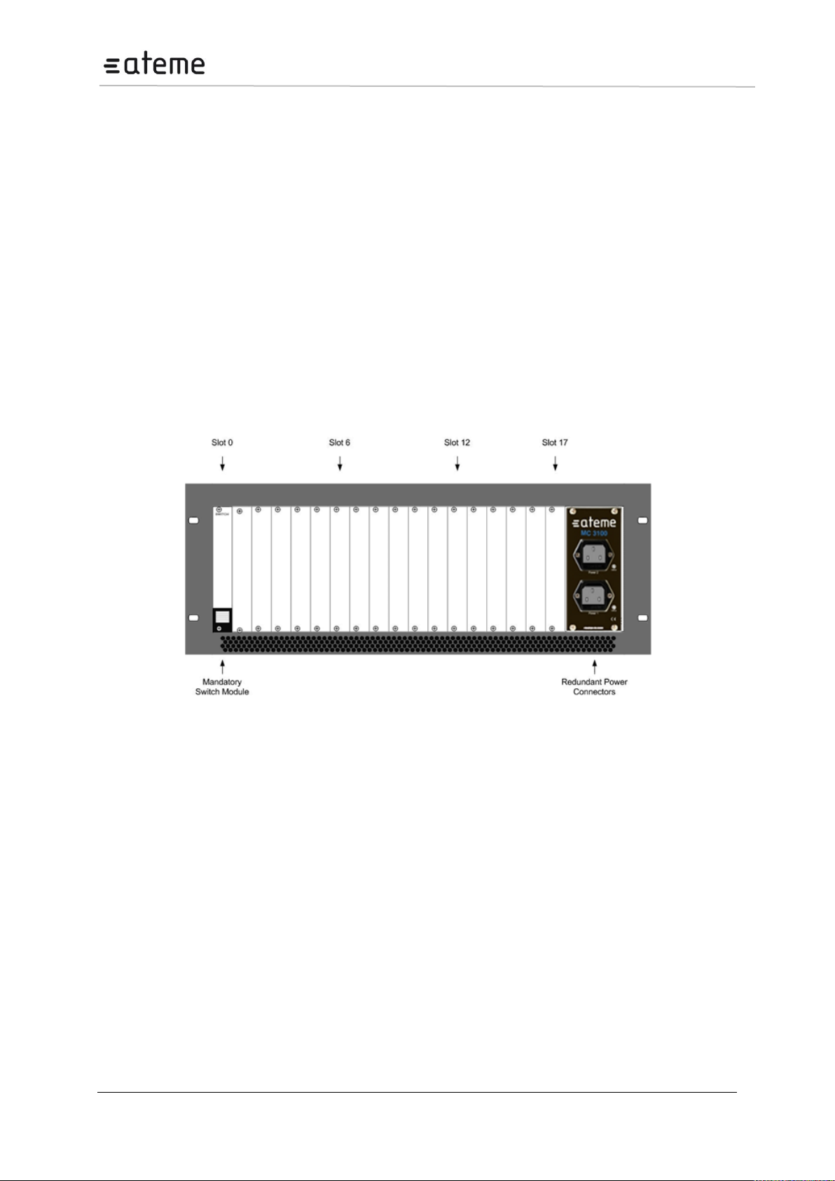
The 4RU chassis consists of a total of 18 slots all of which can host functional modules. Slot number 0
is dedicated to host the switch module and slot number 17 can only host multi-slot input modules.
Alternatively a second switch module can be placed in slot 17 for some redundancy configurations.
The remaining 16 slots are identical and can be occupied by any of the functional modules available.
A 4RU chassis including a mandatory switch module, power supply connectors, and module slots is
shown in Figure below. Power modules and fan modules are inserted from the back.
Figure 1 – 4RU chassis with power connectors, switch module and available slots.
2.1.1 Ventilation
The 4RU chassis has forced air flow from front to back in the chassis, allowing for multiple units to be
stacked above each other with no space in between. However, adequate space must be provided in
front of and behind the unit for effective ventilation.
2.1.2 Replacing the power supply module
The 4RU chassis can be installed with one or two power supply modules. The modules can be
exchanged from the rear of the unit. The chassis delivered with a single power module can be updated
by acquiring additional power module.
If power is lost in one of the Power supplies, the other can feed the entire chassis. It is recommended
to connect each input power at different circuits.
Page 13 / 213
Page 14
MC3x00 – User Manual
Mandatory Safety Instructions
1
The equipment must be installed by a qualified person.
2
For that equipment with grounding, connect the driver before connecting the power
cord. So opposite the power cord must be removed before removing the driver of the
ground.
3
The equipment must be installed in a restricted area where:
Only qualified technicians have access or who know the most important safety
measures.
Access to the area where the devices are installed will be using a tool, lock and
key, or any other safety device, and in addition the site will be controlled by an
authorized person.
2.2 The 1RU Chassis
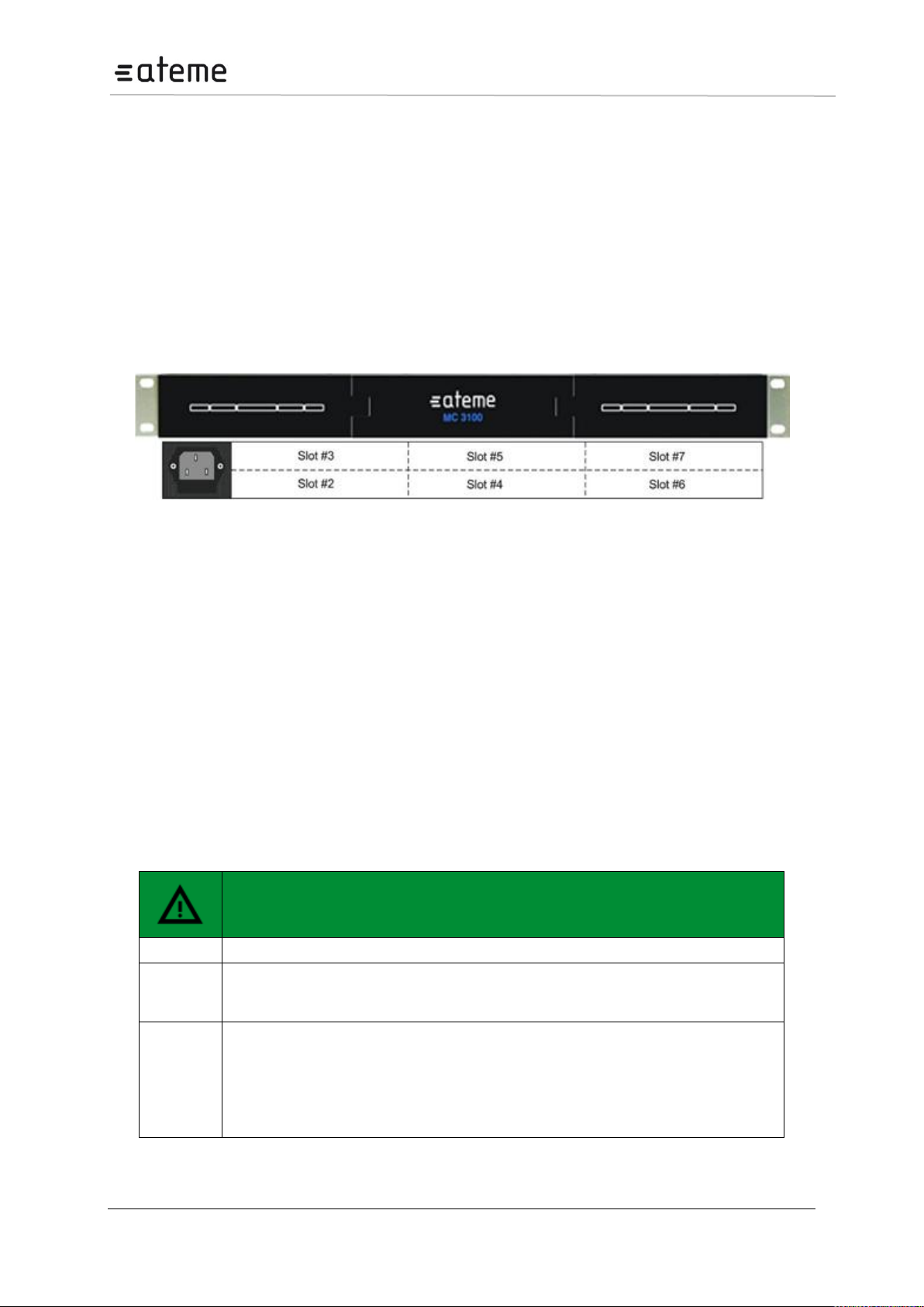
The 1RU chassis consists of a total of 9 slots plus a slot for the switch module. Modules can be
inserted in the front and from the back. Modules inserted in the front are not hot-swappable and can
only be serviced by factory or by authorized service facilities. However, modules inserted from the
back can be serviced in the field. The mandatory switch module is placed in slot 0 located at the front
upper right corner behind the front cover. Slot 1 is at the front below the switch module and slots 8 and
9 are at the front on the left. Slot numbers 2 to 7 are at the back as illustrated in Figure below.
Slot 1 can only support either no module, or an IP IO module or descrambler module. Slots 8 and 9
can only support descrambler modules. Slots 2 to 7 can hold any 1 or 2 slot wide module available.
Figure 2 shows the front and rear view of the 1RU chassis including a mandatory switch module,
power supply connectors, and module slots.
Figure 2 – 1RU chassis with power connector, switch module and available slots; front
and rear view.
2.2.1 Ventilation
The 1RU chassis has forced air flow from left to right allowing for multiple units to be stacked above
each other with no space in between. However, adequate space must be provided on the sides for
effective ventilation.
2.2.2 Replacing the power supply module
The 1RU chassis comes with a single power module. On failure, the case should be sent to the
factory.
2.3 Safety Considerations
The unit must be connected to a grounded power connection. The power input connector is a
disconnect device. To remove the power from the device, the power cables needs to be physically
removed from the power input connector.
Page 14 / 213
Page 15
MC3x00 – User Manual
2.4 Installation
2.4.1 Power supply rating
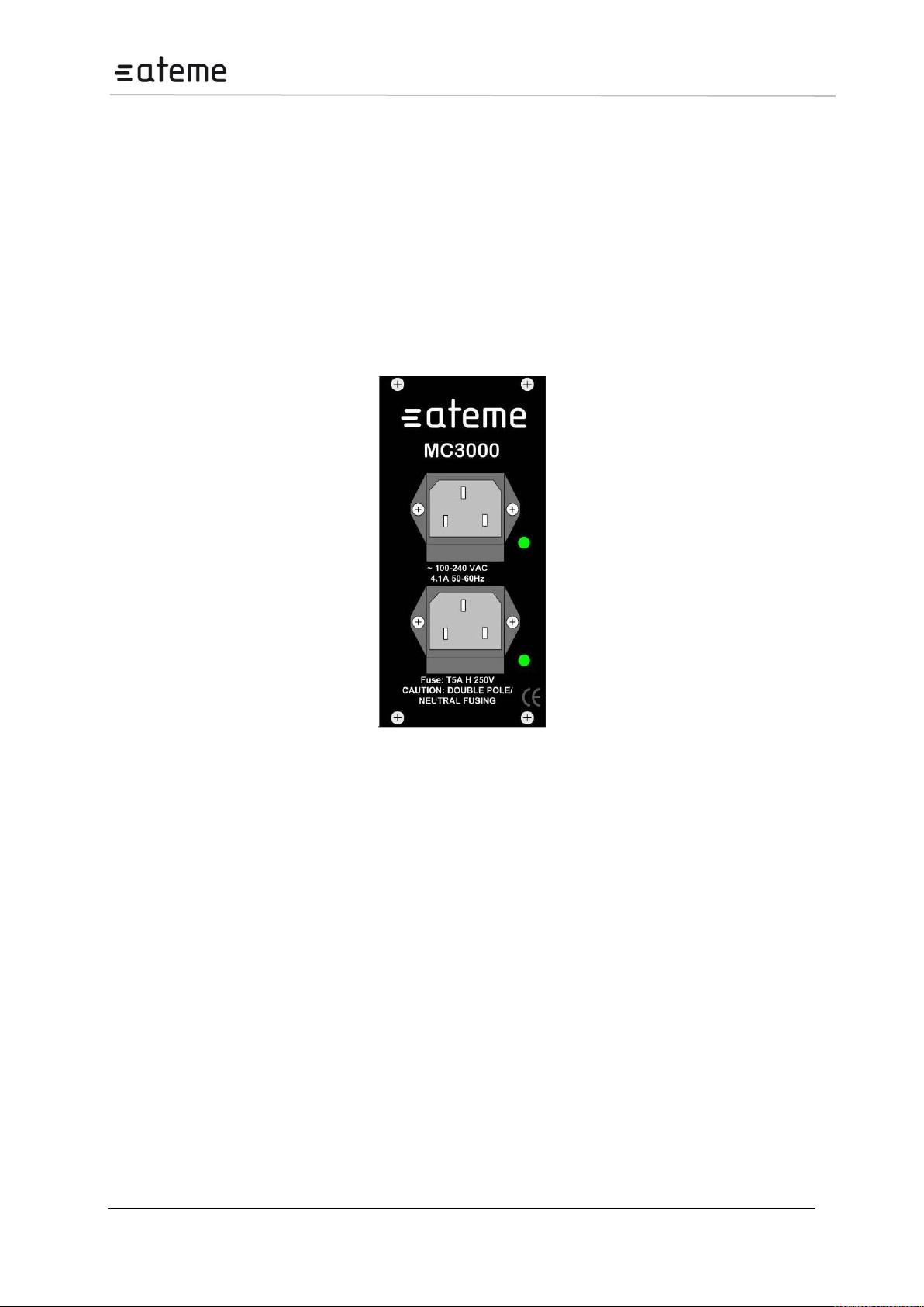
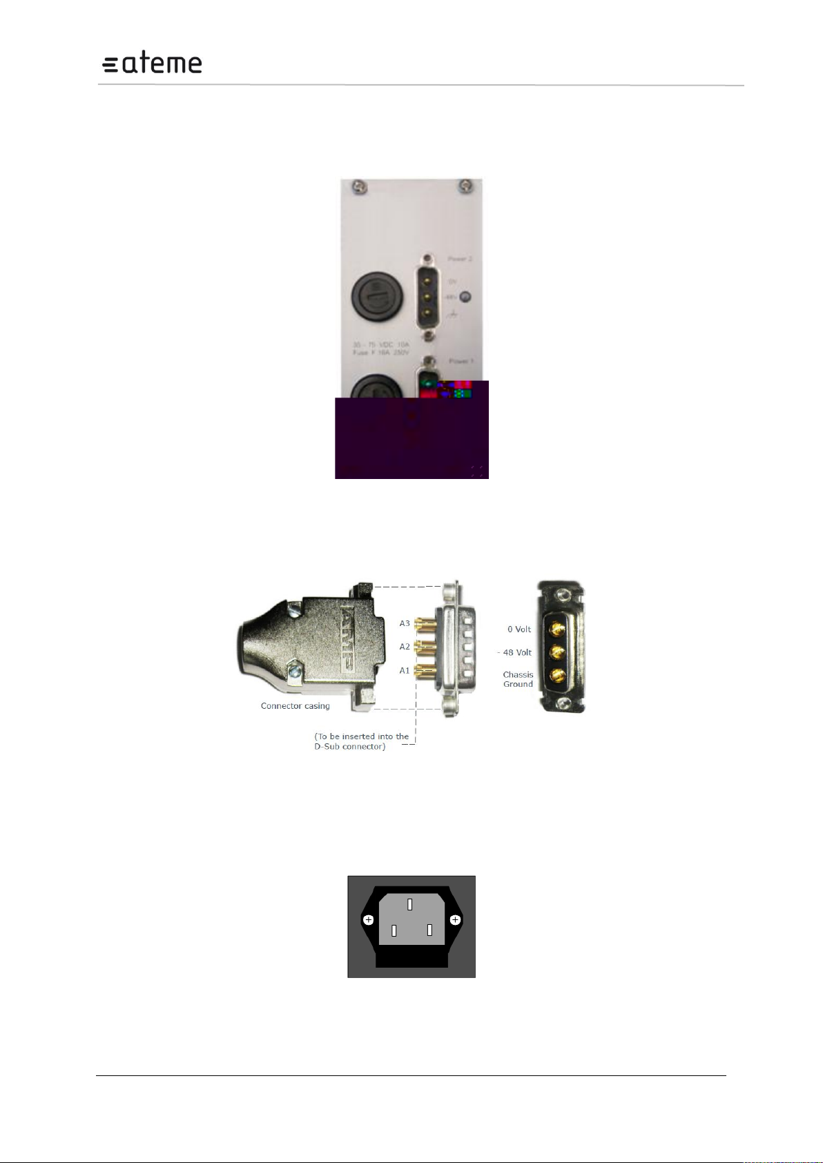
The 4RU chassis is supplied with either a 100-240V AC 50/60 Hz power or 48V DC power. The 100240V AC 50/60 Hz power supply is rated for maximum 300W, 400W. The 48V DC power is rated for
maximum 400W. Figures 3, 4, 5 and 6 below shows the power supply inlets.
The 1RU chassis is supplied with a 100-240V AC 50/60 Hz power rated for maximum 200W.
2.4.2 4RU chassis with 300 and 400W AC Power
The chassis can hold two power supplies for redundancy and has independent power inlets for the two
supplies.
Figure 3 – Power Input for 4RU chassis with 300 and 400 Watt AC power
Page 15 / 213
Page 16
MC3x00 – User Manual
2.4.3 4RU chassis with 400W DC (-48Volt) power supply
The chassis can hold two power supplies for redundancy and has independent power inlets for the two
supplies.
Figure 4 – Front plate of dual 48V Power Supply in a MC3000
Figure 5 – Layout of 48V DC Power Supply Connector
2.4.4 1RU chassis
The power input connector is located at the back of the unit.
Figure 6 – Power Input Connector for 1RU Chassis
Page 16 / 213
Page 17
MC3x00 – User Manual
Manufacturer
Model
wave length [nm]
Max output power1
Finisar
FTLF8519P2xCL
850 nm
-3 dBm
Finisar
FTLF8519P2xNL
850 nm
-3 dBm
Finisar
FTLF8519P2xTL
850 nm
-2.5 dBm
Finisar
FTLF1318P2xCL
1310 nm
-3 dBm
Finisar
FTLF1318P2xTL
1310 nm
-3 dBm
Finisar
FTLF1419P1xCL
1310 nm
5 dBm
Finisar
FTLF1518P1BTL
1550 nm
5 dBm
Finisar
FTLF1519P1xCL
1550 nm
5 dBm
Finisar
FTLF1519P1xNL
1550 nm
5 dBm
Finisar
FTLF1619P1xCL
1550 nm
5 dBm
Finisar
FWLF15217Dxx
1471, 1491, 1511, 1531
1551, 1571, 1591, 1611
5 dBm
Finisar
FWDM16197Dxx
1471, 1491, 1511, 1531
1551, 1571, 1591, 1611
5 dBm
Avago Technologies
AFBR-5710Z
850 nm
-3 dBm
Avago Technologies
AFBR-5715Z
850 nm
-3 dBm
Avago Technologies
AFCT-5710Z
1310 nm
-3 dBm
Avago Technologies
AFCT-5715Z
1310 nm
-3 dBm
OCP
TRXAG1SX
850 nm
-4 dBm
OCP
TRPEG1KVX-E1G
1550 nm
5 dBm
Caution
Use of controls or adjustment or performance of procedures other than those
specified herein may result in hazardous radiation exposure.
1
2.5 Laser Safety
The Optical SFP modules used in the MC3000 and MC3100 products are classified as class 1 laser
products according to IEC 60825-1 and are classified as class 1 laser products per CDRH, 21 CFR
1040 Laser Safety requirements.
Depending on the products configuration, the MC3000 and MC3100 products can be equipped with
multiple insertion modules containing housing for optical SFPs.
When installing SFP modules, please ensure that the module be placed in the housing present at the
front of the IP input/output module. Once inserted, the SFP module will become active.
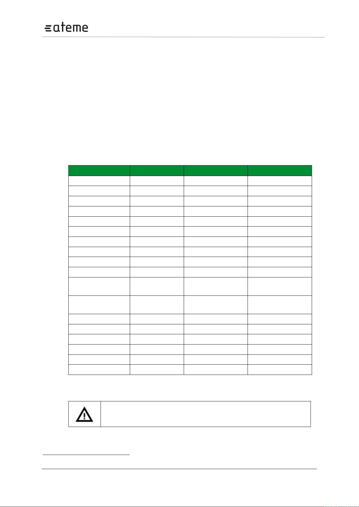
2.5.1 FDA/CDRH Compliant SFP modules
The below list of Optical SFP modules have been selected with regards to the FDA/CDRH laser safety
requirements as the only optical modules allowed used with the ATEME products in the USA, and any
other countries and states that require compliance according to FDA/CDRH laser safety regulations.
2.5.2 Warning: Radiation
Class 1 Laser Safety per FDA/CDRH and EN (IEC) 60825 regulations
Page 17 / 213
Page 18
MC3x00 – User Manual
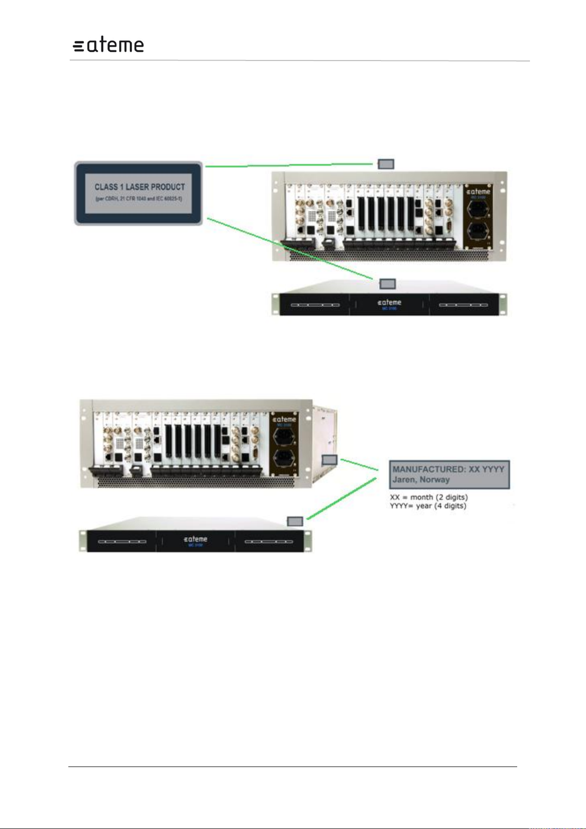
2.5.3 Labels
The following illustrations show the labels attached to the products, according to the standards.
A classification label is attached to the top cover of the MC3000 and MC3100 products.
Figure 7 – Classification label
A CDRH identification label according to 21 CFR 1010.3 is attached on the side of the MC3000 and
MC 3100 products.
Figure 8 – CDRH identification label
Page 18 / 213
Page 19

MC3x00 – User Manual
3 Signal Connection
3.1 Connecting switch modules
Configuration, management and monitoring of you ATEME unit are done via the management port on
the switch module. The switch module will contain the database for the full configuration of the unit.
One switch module (in some configuration two switch modules) must be installed in all 1 RU and all 4
RU chassis.
Please refer to product datasheets for module identification.
3.1.1 Switch module with MMI
The switch module is equipped with one electrical connector (RJ45) for management. Automatic
sensing of 10/100/1000Mbit Ethernet connections is supported. For a 1000Mbit connection the
Ethernet cable must be a category 6 cable.
The management port should be connected to your management network. Please refer to section 4 for
configuration.
3.1.2 Switch module with MMI and IP IO
The switch module with management and two data ports is equipped with three electrical connectors
(RJ45) or one electrical connector (RJ45) and two SFP connectors. Two RJ45 electrical connectors or
two SFP connectors are for data. The last RJ45 electrical connector is for management
Automatic sensing of 10/100/1000Mbit Ethernet connections is supported on all RJ45 ports. For a
1000Mbit connection, the Ethernet cable must be a category 6 cable.
The management port should be connected to your management network and the data port to you
data network carrying the video streaming content. Please refer to section 4 for configuration.
Each port have a unique IP address and both data ports can be used at the same time as wither 2 IP
input ports, 2 IP output ports or 1 IP input and 1 IP output port.
3.2 Connecting Input Signals
Please refer to product datasheets for module identification.
3.2.1 IP Input
The IP input module is equipped with two electrical connectors (RJ45) and one SFP connector. One
RJ45 electrical connector and the SFP connector are for data. The second RJ45 electrical connector
marked “control” is not in use. It is not required to configure the IP address or connect the port to the
IP network.
Automatic sensing of 10/100/1000Mbit Ethernet connections is supported. For a 1000Mbit connection,
the Ethernet cable must be a category 6 cable.
The IP address for both the electrical (RJ45) and the optical (SFP) connectors for data is the same.
Consequently both connectors cannot be used simultaneously. These inputs are automatically
activated by IP connection. The first port activated (by establishing a link to the router) will be the
active port. To activate the other port, remove the cable from the active port.
3.2.2 ASI Input
Each ASI input module has three independent ASI inputs. The ASI connector is a 75Ω BNC
connector. The maximum input rate per connector is 212Mbit/s in burst mode.
The ASI module is equipped with an electrical connector (RJ45) marked “control” that is not in use. It
is not required to configure the IP address or connect the port to the IP network.
Page 19 / 213
Page 20

MC3x00 – User Manual
3.2.3 DVB-S/S2 Input
The DVBS-S/S2 supports both DVB-S (QPSK) and DVB-S2 (DVB-S2 is a SW option). Each DVB-
S/S2 input module has 4 independent L-Band inputs. Each input is a 75Ω F that can be connected
either directly to an LNB, an L-Band distribution amplifier, or switch. The maximum input level is 25dBm. The recommended input level is between -30dBm and -40dBm.
One ASI output port is available for monitoring. Any of the four L-Band inputs can be copied to the ASI
output without affecting the services in use. The ASI connector is a 75Ω BNC connector.
The DVB-S/S2 module is equipped with an electrical connector (RJ45) marked “control” that is not in
use. It is not required to configure the IP address or connect the port to the IP network.
3.2.4 COFDM Input
Each COFDM input module has one 75Ω F connector. The input is distributed to four tuners internally,
so each module can receive four independent frequencies. The maximum input level is -15dBm. The
recommended input level is between -30dBm and -50dBm. (An older version of this module exists with
different input levels.)
One ASI output port is available for monitoring. Any of the four COFDM inputs can be copied to the
ASI output without affecting the services in use. The ASI connector is a 75Ω BNC connector.
The COFDM module is equipped with an electrical connector (RJ45) marked “control” that is not in
use. It is not required to configure the IP address or connect the port to the IP network.
3.2.5 DVB-T/T2 Input
Each DVB-T/T2 input module has one or four 75Ω F connector. For the module having one input
connector, the input is distributed to four tuners internally, so each module can receive four
independent frequencies. For the module with 4 inputs, each input is directly connected to a tuner.
The maximum input level is -10dBm (both modules). The recommended input level is between 20dBm and -40dBm (optimal lever will depend on modulation used).
Page 20 / 213
Page 21

MC3x00 – User Manual
3.2.6 QAM A/C Input
Each QAM input module has one 75Ω F connector. The input is distributed to four tuners internally, so
each module can receive four independent frequencies. The maximum input level is -15dBm. The
recommended input level is between -30dBm and -50dBm.
One ASI output port is available for monitoring. Any of the four QAM inputs can be copied to the ASI
output without affecting the services in use. The ASI connector is a 75Ω BNC connector.
The QAM module is equipped with an electrical connector (RJ45) marked “control” that is not in use. It
is not required to configure the IP address or connect the port to the IP network.
3.2.7 8VSB Input
Each 8VSB input module has four independent 75Ω F connectors.
One ASI output port is available for monitoring. Any of the four 8VSB inputs can be copied to the ASI
output without affecting the services in use. The ASI connector is a 75Ω BNC connector.
The 8VSB module is equipped with an electrical connector (RJ45) marked “control” that is not in use. It
is not required to configure the IP address or connect the port to the IP network.
3.2.8 QAM-B Input
Each QAM-B input module has four independent 75Ω F connectors.
One ASI output port is available for monitoring. Any of the four QAM-B inputs can be copied to the ASI
output without affecting the services in use. The ASI connector is a 75Ω BNC connector.
The 8VSB module is equipped with an electrical connector (RJ45) marked “control” that is not in use. It
is not required to configure the IP address or connect the port to the IP network.
3.3 Connecting Output Signals
3.3.1 IP Output
The IP output card is equipped with both an electrical connector (RJ45) and one optical (via the SFP
module) for data. The RJ45 connector marked “control” is not in use. It is not required to configure the
IP address or connect the port to the IP network.
Automatic sensing of 10/100/1000Mbit Ethernet connections is supported. For a 1000Mbit connection,
the Ethernet cable must be a category 6 cable.
The IP address for both the electrical (RJ45) and the optical (SFP) connectors for data is the same.
Consequently, both connectors cannot be used simultaneously. These inputs are automatically
activated by IP connection. The first port activated (by establishing a link to the router) will be the
active port. To activate the other port, remove the cable from the active port.
3.3.2 ASI Output
Each ASI output module has four independent ASI outputs. The ASI connector is a 75Ω BNC
connector. The maximum output rate per connector is 212Mbit/s in burst mode.
3.3.3 QAM Output
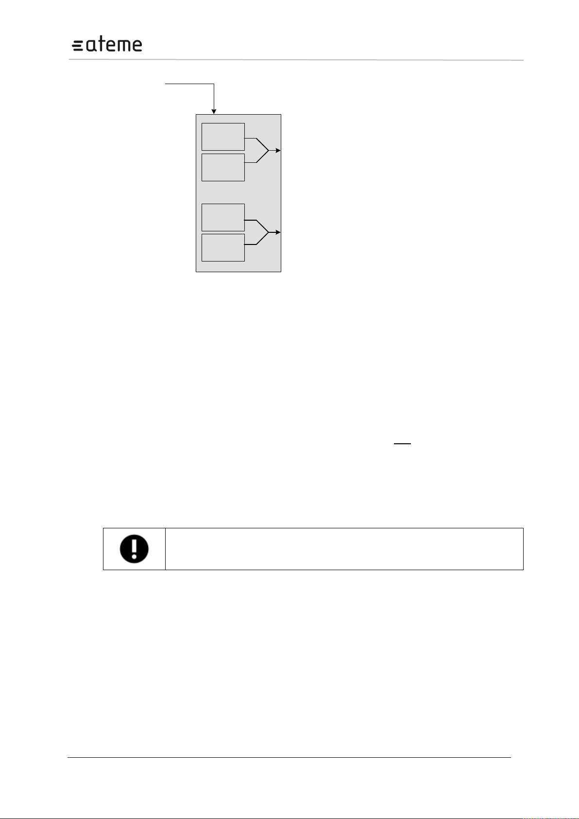
Each QAM output module has two 75Ω F connectors which carry up to sixteen frequencies.
Page 21 / 213
Page 22
MC3x00 – User Manual
Data from backplane
MOD 1
MOD 2
MOD 3
MOD 4
QAM Modulator board
To run HD content, a pair of HD/SDI approved BNC connector and cable is necessary.
Figure 9 – QAM Modulator
3.3.4 COFDM Cable Output
Each COFDM output module has two 75Ω F connectors which carry up to four frequencies.
3.3.5 MPEG-2/4 SD/HD SDI Decoder
The MPEG-2/4 SD/HD decoder enables decoding in either MPEG-2 SD/HD or MPEG-4 AVC SD/HD
format. The module has two outputs that can be either SDI or HD-SDI with embedded audio and VBI.
It is possible to configure the decoder’s channel B to route its audio outputs to channel A, resulting in
channel A (the first two output ports) having the video stream along with four different audio tracks.
Channel B will then have no output.
There are two steps involved to obtain this configuration:
On the module itself, set dip switch 6 to on.
In the GUI, set Input Source for both Output A and B to the same video stream.
Page 22 / 213
Page 23
MC3x00 – User Manual
3.3.6 MPEG-2/4 SD/HD Composite Decoder
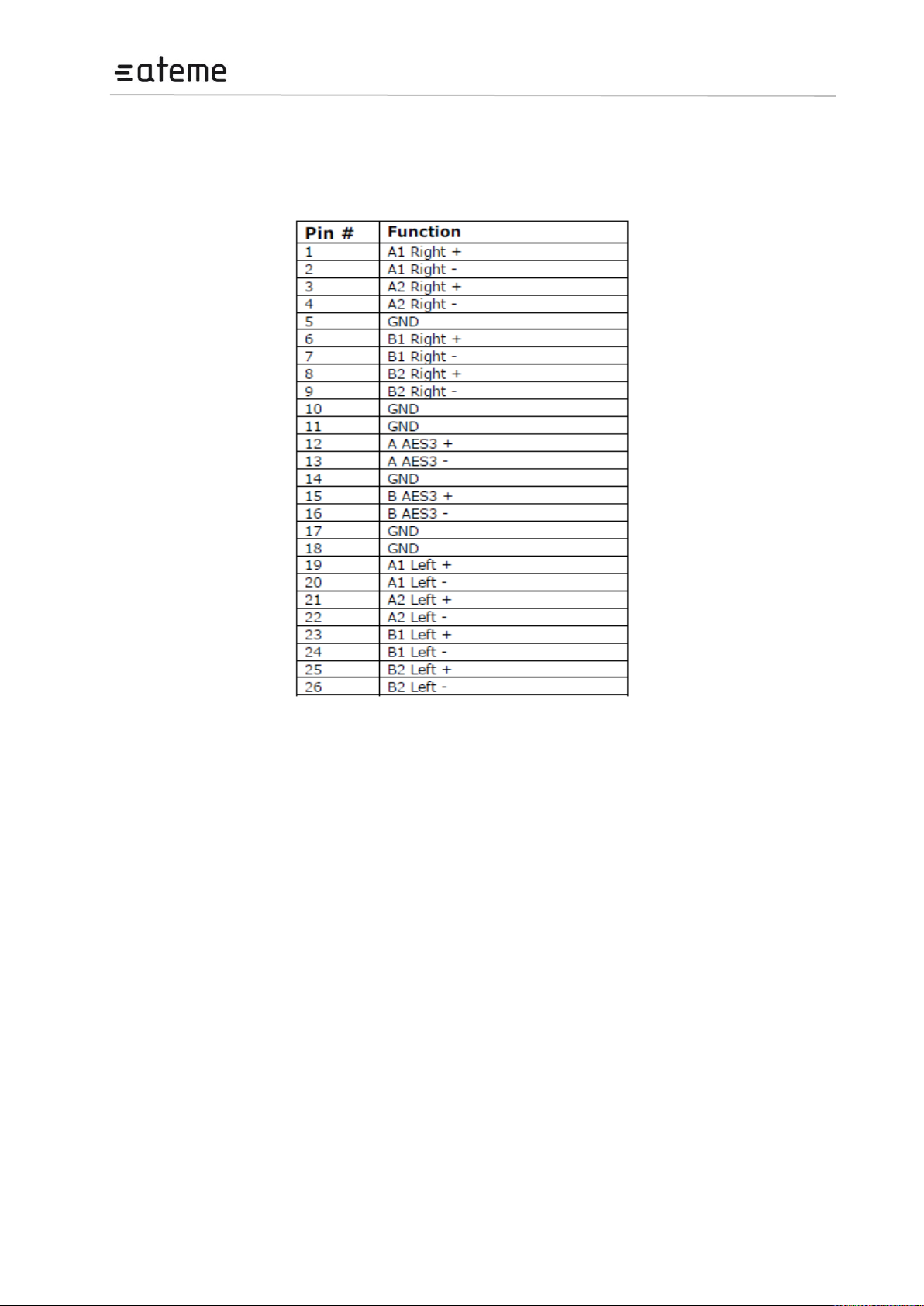
The MPEG-2/4 SD/HD decoder enables decoding in either MPEG-2 SD/HD or MPEG-4 AVC SD/HD
format. The module has two composite BNC outputs for video and one HD DSUB 26 male connector
for audio. This pin-out for this is as follows:
3.3.7 MPEG-2/4 SD/HDHigh Performance Decoder with RF
Modulation and Stereo sound
The High Performance Dual Decoder Module will provide two PAL modulated and RF up-converted
services with excellent RF characteristics. The RF up-converted output for the two channels are
combined internally and presented on a single female F connector.
The module has a test output with both channels; the test output connector is a single female F
connector and the power level is -23dB from the main output.
The module covers the complete VHF/UHF band from 47MHz to 862MHz and NICAM or A2 stereo is
provided as an SW option. A module delivered as mono can later be upgraded to support NICAM or
A2 stereo by purchasing a SW license.
The RF output can be muted with an external unit by applying 5V to the mute connector. Channel A
and Channel B can be muted individually. The connector for Mute is a 2.5 mm headphone jack. For
more information on this functionality, contact ATEME’s Support Team.
The High Performance Dual Decoder with RF Modulation and Stereo sound is two slots wide.
3.3.8 Quad Decoder with RF Output
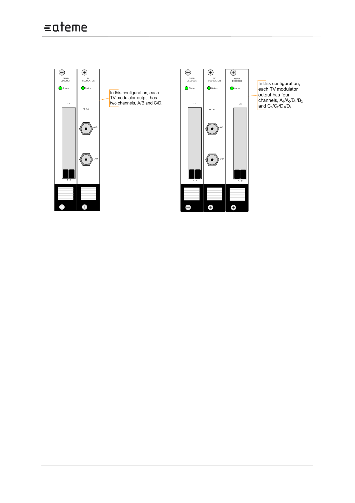
The Quad Decoder solution consists of up to 1 or 2 individual decoder modules and a TV modulator.
Each decoder module decodes 4 MPEG-2/4 services and the TV modulator modulates up to 8 analog
RF TV channels.
Page 23 / 213
Page 24
MC3x00 – User Manual
Figure 10 – Two-Slot Wide Quad Decoder
Figure 11 – Three-Slot Wide Quad Decoder
With the 4 channel solution (two slots wide, see Figure 10 all the channels are fully agile and can be
set to any frequency in the UHF/VHF range. On the other hand, the 8 channel solution (three slots
wide, see Figure 11) has 2x2 channels paired with neighboring channels.
Refer to Section 7 for information on how to configure the decoder.
3.3.9 FM Radio Output
The FM radio module has built-in FM modulation and up-conversion to the FM band. Its FM upconverted output is a female F connector.
Each module is one slot wide and can offer up to eight channels. The FM output can cover the
complete band from 87.5MHz to 108MHz. All eight channels are combined into a female 75 Ω F
connector.
The options to enable RDS or insert RDS information, as well as enable outside management are
presented in the GUI.
The RF output can be muted with an external system by applying 5V to the mute connector. Muting
the input mutes all channels available on the RF output connector.
Page 24 / 213
Page 25
MC3x00 – User Manual
If you upgrade a chassis from SW version 2.16 or lower to SW 3.xx, then switch
module in the chassis must be replaced with a new switch module having MMI
support. The configuration must be moved to the switch module from the current MMI
module residing on an input module. The input module must be reconfigured to a slave.
Please refer to Upgrade Guide for more information.
Ensure that caching is disabled in the web browser.
4 Administrative Settings Configuration
This chapter describes how to conduct initial configuration of the unit, such as setting its IP address,
changing the GUI’s password, setting the unit’s time as well as handling licenses for the modules in
the unit.
4.1 Accessing the Web Interface
All modules in the unit are controlled via the web interface provided with it. The unit Man Machine
Interface (MMI) software runs on the switch module via the connector marked as "Control"
Old switch board do support only v2.x. Any board can be used as MMI
New switch board supports only v3.x. With v3.x, Only the switch module can be configured as MMI.
The new switch module can also handle 2 Gbe Ethernet ports and genlock input
Default MMI IP address is 192.168.1.100. To change the network settings of the device please follow
the steps described below.
Connect a PC directly to the device (the Ethernet port marked "control" on the switch module) with an
Ethernet cable.
Set the IP address of the Ethernet adapter of the PC to a fixed address in the same segment (e.g.
192.168.1.99). Refer to the operating system’s manual for details on setting the IP address on the PC.
Start an internet web-browser and type 192.168.1.100 in the address field.
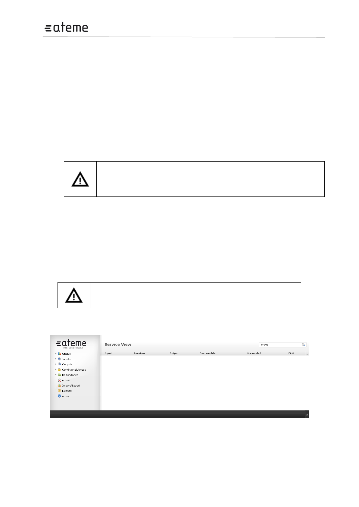
The following screen will appear though the exact configuration of the unit will vary.
Figure 12 – Web Home Page
Page 25 / 213
Page 26
MC3x00 – User Manual
If you have previously connected to a unit with the same IP address, the ARP table on
your computer might be inaccurate. To delete the old ARP entry, type arp-d 192.168.1.100
in a command prompt.
The screen area is divided into several sub-areas:
a Navigation Pane on the left,
a main display page on the right and footer at the bottom of the page.
The Navigation Pane is used to access various nodes, while the footer displays alarms. Please note
that the alarm area can be expanded by clicking on the arrow in the right bottom corner.
4.1.1 Assigning an IP Address
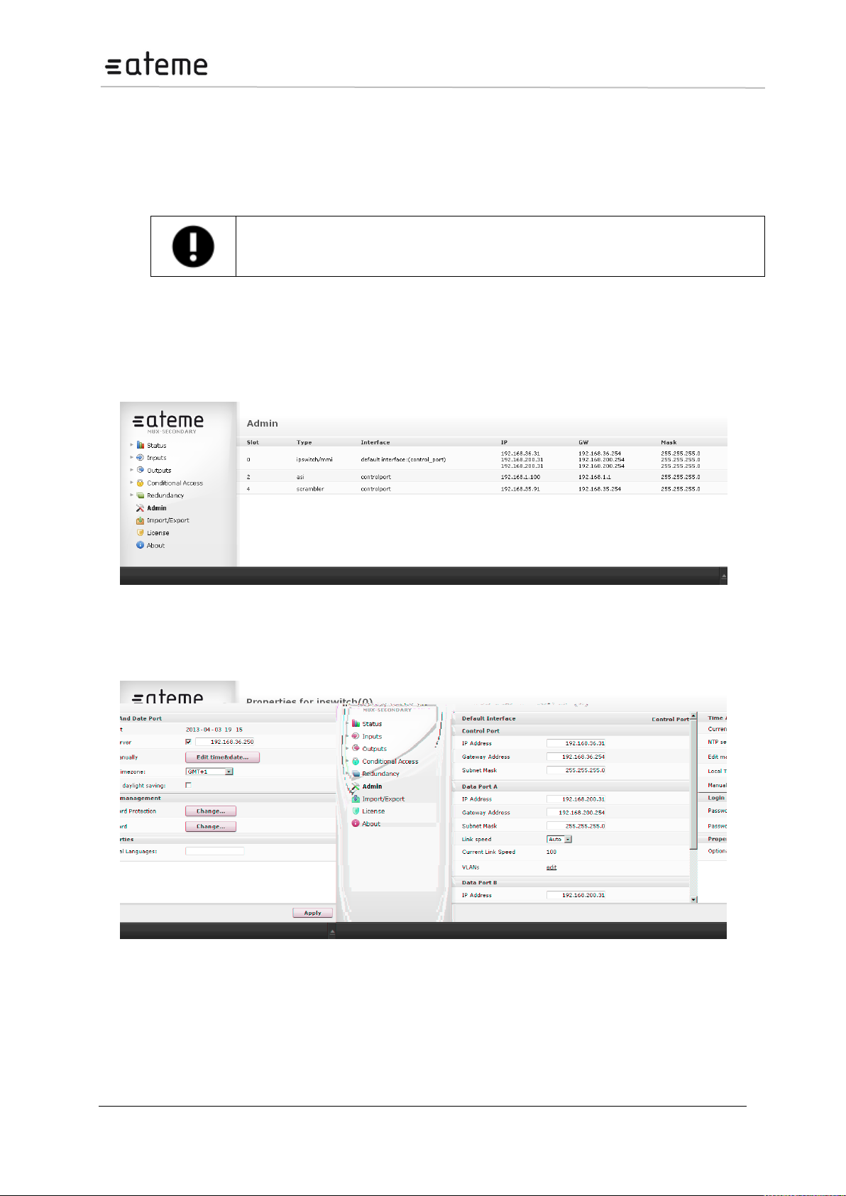
Click on the Admin node in the Navigation Pane and the window in Figure below will be displayed.
This window shows all installed modules with their respective network settings; the MMI module is in
slot 0 or slot 17 (marked as mmi in Type).
Figure 13 – Admin View
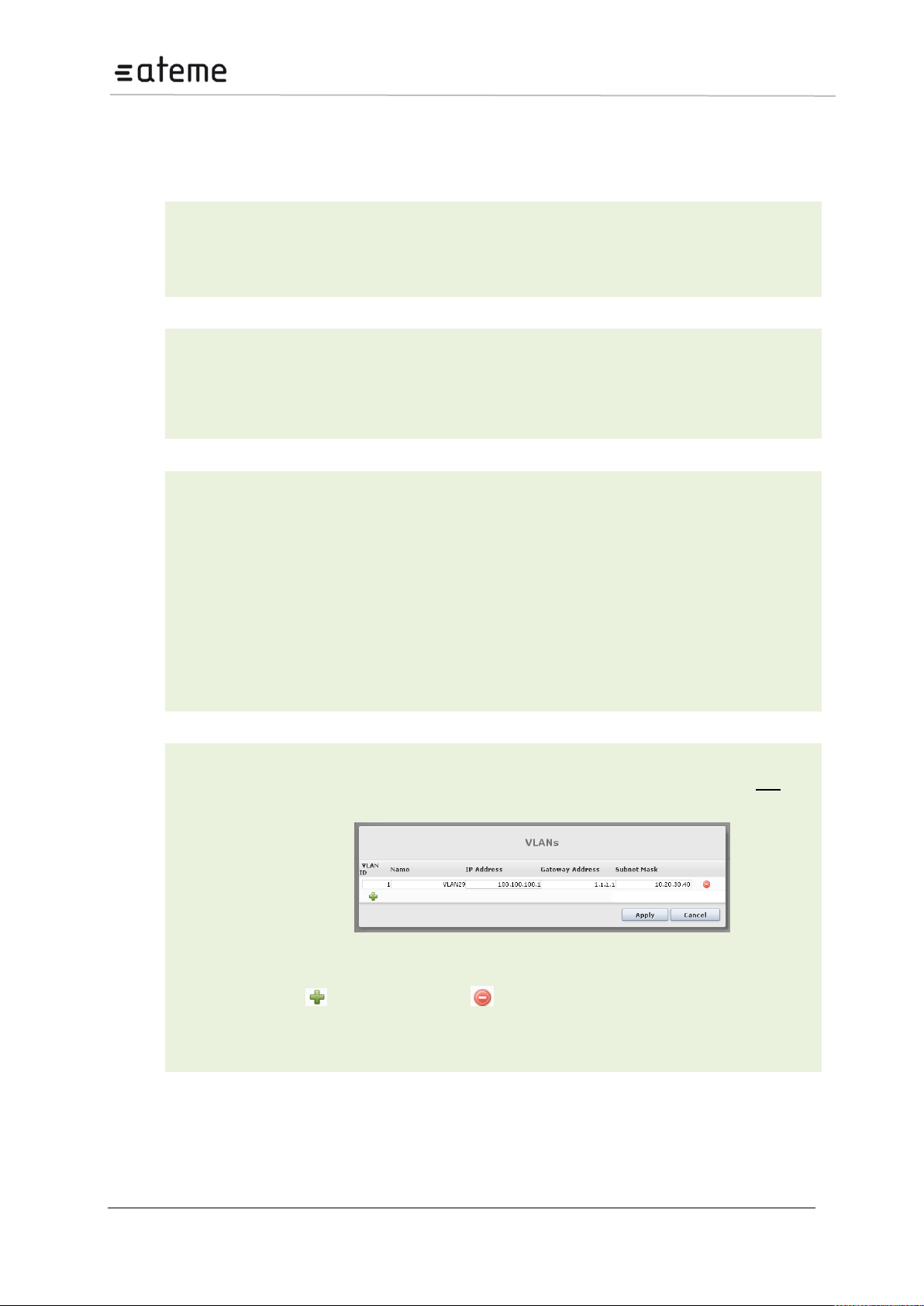
Select the switch module hosting the MMI and a module configuration similar to the one below Figure
below will be displayed.
Figure 14 – Admin Properties View
Page 26 / 213
Page 27
MC3x00 – User Manual
Default Interface
This parameter allows you to select the Management Port to be used for
managing the Web GUI.
For Switch modules with IP interfaces, the Management Port can be the
Control Port, Data Port, or a VLAN (previously added).
IP Address
IP address used solely for management. It cannot be used for multicast
reception as it is not for data input.
Gateway Address
Gateway address of the network used for management
Subnet Mask
Subnet mask
IP Address
IP address used for multicast reception
Gateway Address
Gateway address of the network used to access external resources
Subnet Mask
Subnet mask
Link Speed
Choose from:
Auto
10
100
1000
Current Link Speed
Current detected link speed of the Ethernet interface
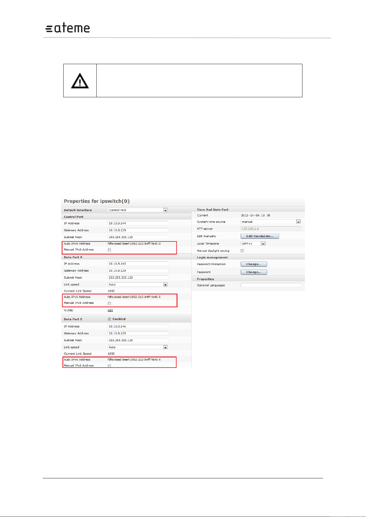
VLANs
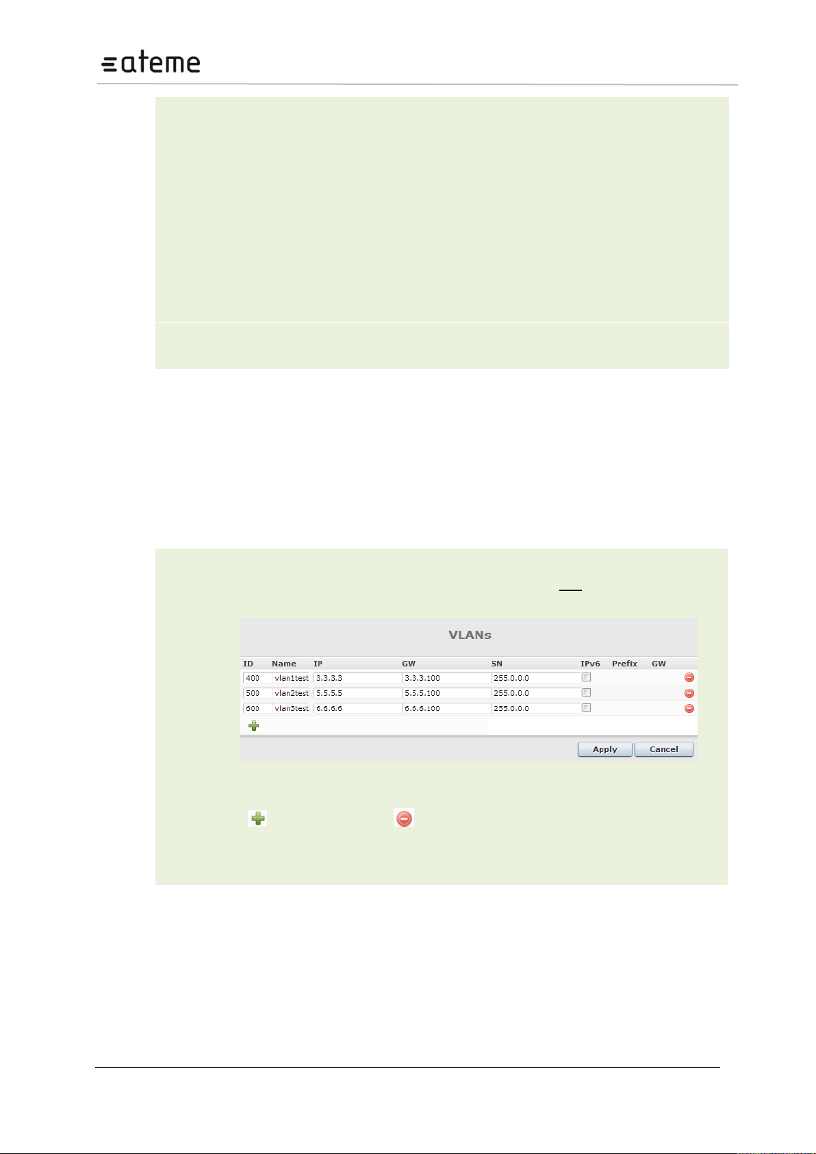
Each IP Input port supports up to three Virtual LANs (VLANs) and they can be defined
in the Admin Properties view. The VLANs may then be associated with IP input
streams when configuring input multicasts. To add and remove VLANs, click edit. The
dialog below will be displayed:
Figure 15 – Setting up Virtual LANs
Click to add VLAN tags and to remove them.
If an active VLAN is removed, the associated IP inputs are reset so that they will not be
part of that particular VLAN group.
In the Admin Properties view, it is possible to configure the Default Interface, Control Port, and
Data Port. Control ports on all input, output and processing except scrambling, bulk descrambling
and EPG modules do not need to be configured.
Default Interface
Control Port
Data Port
VLAN
Page 27 / 213
Page 28
MC3x00 – User Manual
Please note that the following addresses ranges are reserved for internal use and
not available to be configured:
Switch: 192.168.0.xxx
Switch w/ IP: 192.168.0.xxx and 192.168.2.xxx
Save the settings and connect the unit to your local network. Reconnect to the Web GUI using the
MMI address.
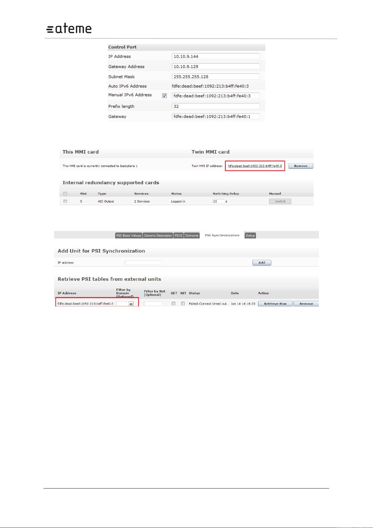
4.1.2 IPv6 Address Support
IPv6 support is available for management and data ports of the Switch module, both Control and IP
versions. The following options are supported:
Support for simultaneous IPv4 and IPv6 addresses, both for management and data ports.
Management (GUI/SNMP) using IPv6 address
IP inputs using IPv6 addresses
IP output using IPv6 addresses
4.1.3 Management GUI
Figure 16 – IPv6 Address in Admin Page
Page 28 / 213
Page 29
MC3x00 – User Manual
Figure 17 – Manual IPv6 Address
Figure 18 – IPv6 Internal Redundancy
Figure 19 – IPv6 PSI Synchronization
Page 29 / 213
Page 30
MC3x00 – User Manual
Default interface
Default interface for Management interface. This can be selected between
control and dataports, as well as any configured VLANs.
Auto IPv6 Address
All interfaces will automatically get an IPv6 address which is generated
based on router advertisements. The address will have a correct prefix, and
be unique on the connected network.
Manual IPv6 Address
When enabling Manual IPv6 Address, the port can be configured with a
manual IPv6 Address. Prefix length and Gateway address is also set.
IPv6 NTP server
The unit can connect to an IPv6 NTP server by inserting a valid IPv6
address in the “NTP server” field.
Internal Redundancy
The twin MMI card can use an IPv4 or IPv6 address.
PSI Synchronization
The PSI Synchronization units can use an IPv4 or IPv6 address
VLANs
Each IP Input port supports up to three Virtual LANs (VLANs) and they can be defined in the
Admin Properties view. The VLANs may then be associated with IP input streams when
configuring input multicasts. To add and remove VLANs, click edit. The dialog below will be
displayed:
Figure 20 – Setting up Virtual LANs
Click to add VLAN tags and to remove them.
If an active VLAN is removed, the associated IP inputs are reset so that they will not be part
of that particular VLAN group.
4.1.4 Management over IP-Data Port and VLANs
In the Admin section of the MMI card, it is now possible to set the default interface for the
Management interface. This includes the GUI, Maintenance Center and SOAP operations.
This will allow you to configure the IP dataports on the switch card, or a configured VLAN for the
default management interface.
To configure the VLANs settings, enter the following data below:
Page 30 / 213
Page 31
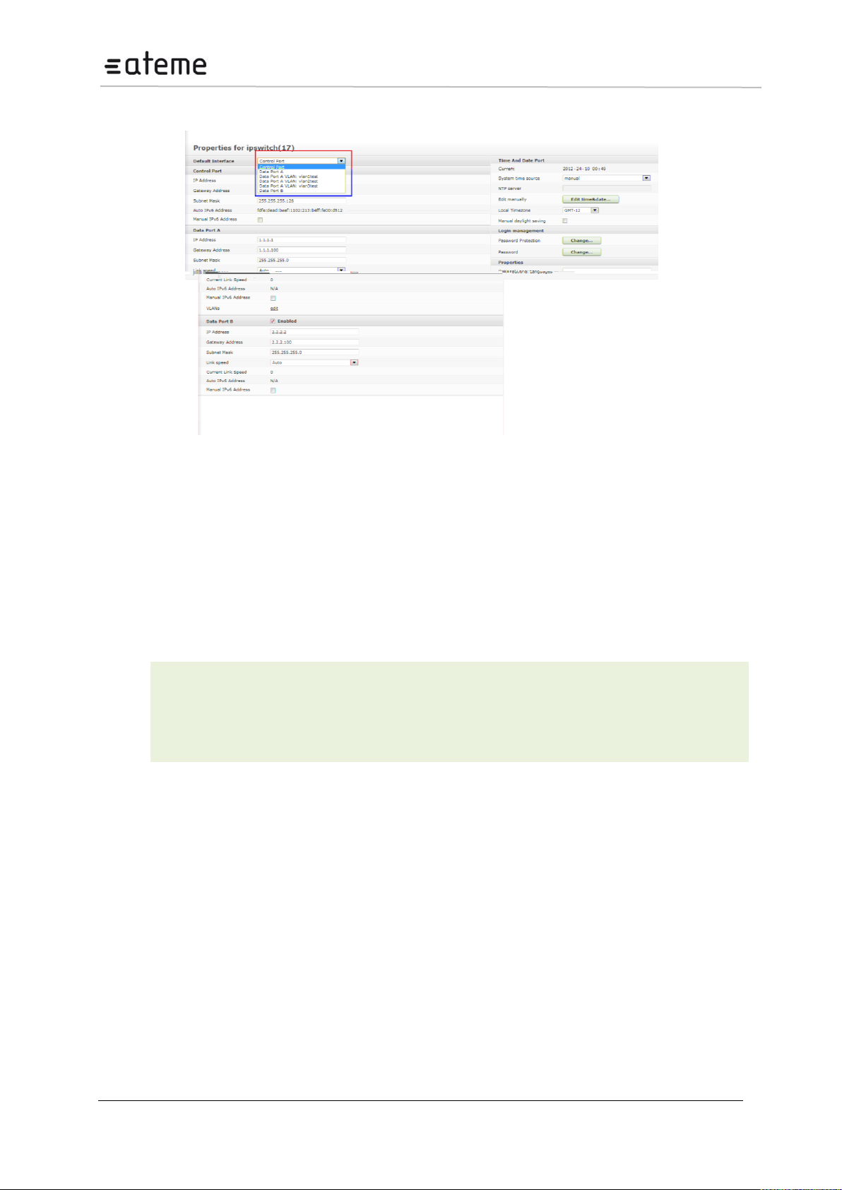
MC3x00 – User Manual
IP Address
IP address of the NTP server
Local Timezone
Your local timezone
Manual
Daylight Saving
Enabling this setting adds the summertime hour to the clock.
After configuring VLANs we can see it in the drop down list in the control port refer below figure.
Figure 21 – Setting up Virtual LANs via Management port
4.1.5 Internal Time Clock Setting / Network Time Protocol (NTP)
Server
The unit internal time may be configured manually, or it may be configured with a Network Time
Protocol (NTP) server to set and update the system’s date and time.
Open the Admin view in the Navigation Pane and select the module hosting the Man Machine
Interface (MMI).
To configure the NTP Server settings, enter the following data below:
Page 31 / 213
Page 32

MC3x00 – User Manual
To set the internal time manually, simply click on Edit time & date to produce the dialog below.
Figure 22 – Setting the Time and Date
Set the date and time accordingly.
Once the internal time has been configured, it will be displayed in the Current Time field, under the
Time and Date section.
4.1.6 Password Protection in the GUI
For enhanced security the Web interface supports password protected access. This feature is disabled
by default but may be enabled easily from the GUI.
To authenticate GUI access, click Change under the Password Protection entry in Login
Management (part of the Admin Properties View). Check the appropriate checkbox and click Apply.
Reboot the MMI module for this change 3(. )3fgk23(d)e 10(de)4(f)efw.
Page 32 / 213
Page 33
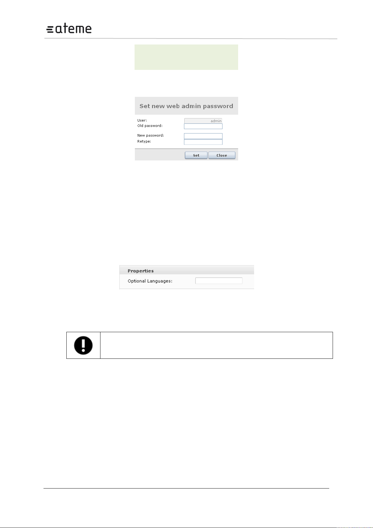
MC3x00 – User Manual
User
admin
Default password
admin
Language codes are defined in the ISO 639 specification.
To change the password click Change. The following dialog will appear:
Figure 25 – Changing the Password
Type in the new password and click Set. Finally, click Close to exit the dialog. Reboot the MMI module
for the new password to take effect.
4.1.8 Optional Languages
It is possible to specify one or two default languages which will always be available when configuring
decoder modules. Since the drop-down list of available languages only includes languages currently
present in the transport stream, this enables the operator to select languages expected to be present
in the transport stream at a later point in time.
Open the Admin view in the Navigation Pane and select the module hosting the MMI.
Figure 26 – Optional Languages
Enter up to two additional languages for the Optional Languages field. Language codes should be
separated by a comma, e.g., nor,dan.
Page 33 / 213
Page 34
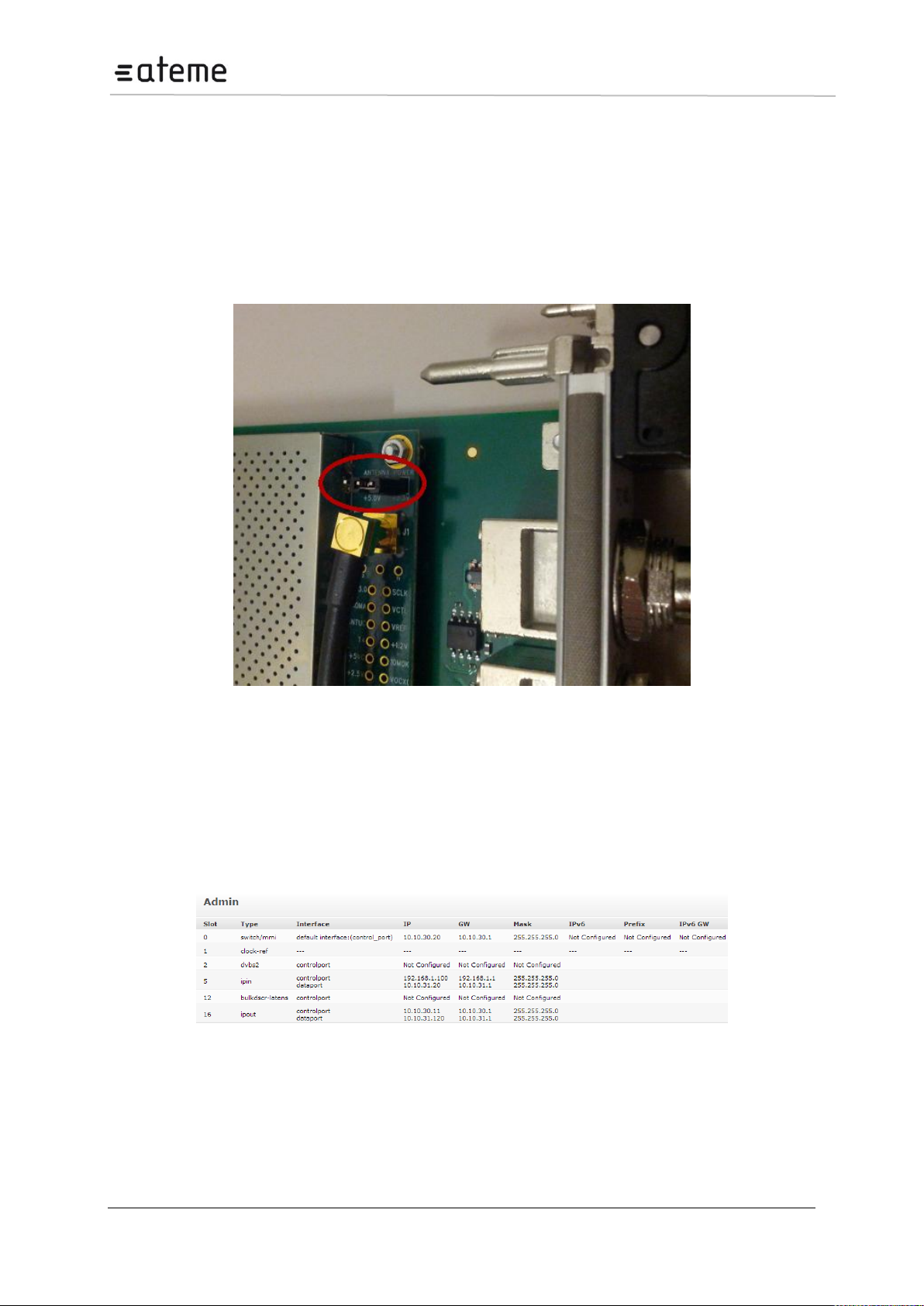
MC3x00 – User Manual
4.2 Configuration of Clock reference module
The Clock Reference module is used to generate a synchronized PPS and 10 MHz reference signal to
be used by the MMI module for various applications. The clock source can be a signal from a GPS
antenna or an external PPS signal.
The module can power an active GPS antenna with 3.3V or 5.0V. The default output voltage is 3.3V,
but this is selectable with the jumper close to the antenna input cable. This is shown in the figure
below.
Figure 27 – Clock reference module.
4.2.1 Configuration
In order to enable the clock source form the Clock Reference module in the unit, the module will first
have to be configured, and then selected from the MMI settings.
To configure the clocks source for this module, select the Admin page in the Navigation pane then
select "clock-ref" to access the configuration.
Figure 28 – Configuration of clock reference module
Page 34 / 213
Page 35
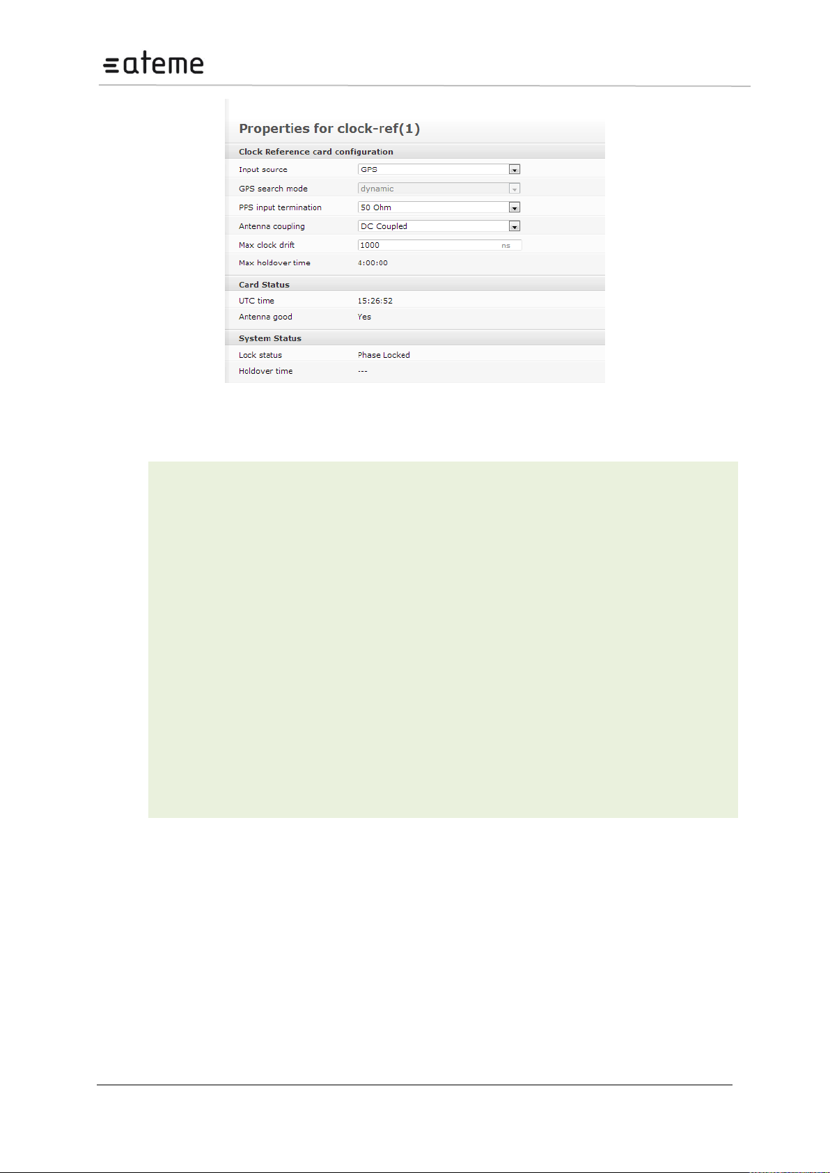
MC3x00 – User Manual
Input source
Select GPS or PPS Input
PPS input
termination
The termination on the PPS Input is selectable between 50 Ohm and high
impedance.
Max clock drift
Set the maximum allowable drift of the internal PPS signal. If the module loses
the external reference signal (GPS or PPS), the module will enter holdover
mode. This parameter sets the maximum allowed drift of the internal PPS signal
in ns, and thus the maximum holdover time (based on the holdover oscillator
performance).
Max holdover time
Specifies the maximum holdover time, which is given by the value in “Max clock
drift”.
Antenna coupling
Select between DC coupled and AC coupled. DC coupled is default, and should
be selected when the Clock Reference module is providing the DC power for the
GPS antenna. AC coupled should be selected when antenna power is provided
externally.
UTC time
Specifies UTC time derived from GPS.
Lock status
Specifies the lock status of the Clock Reference module.
Holdover time
Specifies how long time the module has been without a synchronization input.
Figure 29 – Parameters of clock reference module
The following parameters are there in Clock reference module.
The next step is to configure the MMI card to use the Clock Reference module as the main clock
source. This is available in the configuration of the Swtich or IP+Swtich card. To configure this, select
the Admin page in the Navigation pane then select the “mmi” module to access the configuration.
Page 35 / 213
Page 36
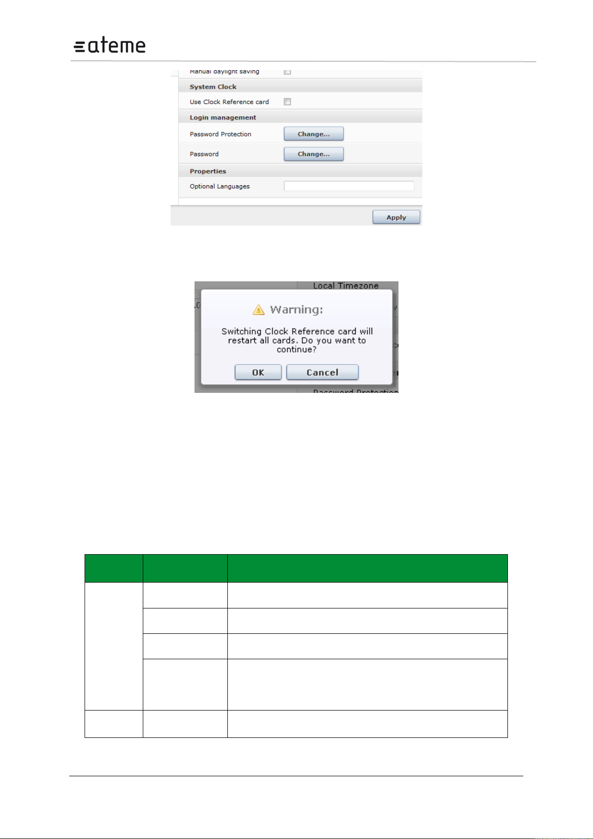
MC3x00 – User Manual
Card
Type
License
Description
adm
hd-decoding
Enables decoding in HD.
Dolby Digital Plus
Enables Dolby Digital decoding
osdm
Enables the On Screen Display option for the decoded output.
stereo
Enables the A2/NICAM output and sound options.
* This license is applicable to ADM modules with RF modulator
cards only.
audiolevel
number-of-audio-
pids
Enables the number of audio PIDs with audio leveling.
Figure 30 – MMI Clock Reference selection
Enable the Use Clock Reference card option, and once selected this will bring up a warning:
Figure 31 – MMI Clock Reference warning
A reset of the unit is required in order to switch the clock source to the Clock Reference module. This
will ensure all cards in the unit are synchronised correctly to this card. Once OK is clicked, and the
changes accepted by clicking on the Apply button, the unit will then be reset. After reboot, the new
clock source is activated.
4.3 Licensing
Licenses for modules in the unit are hosted by individual cards. Hence, the available features will not
be determined before the cards are registered or logged into the MMI board. The table below lists all
available licenses:
Page 36 / 213
Page 37

MC3x00 – User Manual
bulkdscr
number-of-
descrambled-
services
Enables the number of services for bulk descrambling.
verimatrix
Enables communication with the Verimatrix CA system
latens
Enables communication with Latens system
cofdmout-
cable
modulation-cofdm
Enables COFDM modulation for the output.
num-ts
Enables the number of maximum possible output multiplexes.
ddm-mk2
osdm
Enables the On Screen Display option for the decoded output.
stereo
Enables the A2/NICAM output sound options.
* This license is applicable to DDM modules with RF modulator
cards only.
dvbs2
dvbs2
Enables the DVB-S2 8PSK, QPSK and APSK demodulation
options. APSK is only available for HW rev 2.0.
dvbs2-input-
multistream
Enables Multistream option for the DVB-S2 module.
epg
epg
Enables EPG.
asiout
mip-inserter
Enables MIP on the ASI output port.
switch/ipin
ipin-pro-mpeg-fec
The ip-pro-mpeg-fec license is only available for the second
generation IP-out HW with a larger FPGA.
seamless-ip-in
Enables IP input seamless switching
switch/ipout
ip-out-mpts
MPTS refers to Multiple Program Transport Stream. Without the ipout-mpts license, only SPTS (Single Program Transport Stream) is
available.
ip-pro-mpeg-fec
Enables Forward Error Correction (FEC). This license is only
available for the second generation IP-out HW with a larger FPGA.
output-
redundancy
Enables output redundancy for the module.
qamout-a
modulation-qam
Enables QAM modulation for the output.
num-ts
Enables the number of maximum possible output multiplexes.
dvb-t2
dvbt2-input
Enables the DVB-T2 demodulation options.
scrambler
number-of-
scrambled-
services
Enables the number of services to be scrambled and the
corresponding encryption algorithm.
aes-cbc-irdeto
Vendor specific scrambling license.
pvr-mode-pes-
clear
Enables PVR mode for the scrambler and ensures that the pes
headers are not scrambled.
* pes-clear and pvr cannot be active simultaneously
tvmod
modulation-analog
Enables PAL or Secam modulation for the output.
num-channels
Enables 4 or 8 channels to be output.
Page 37 / 213
Page 38
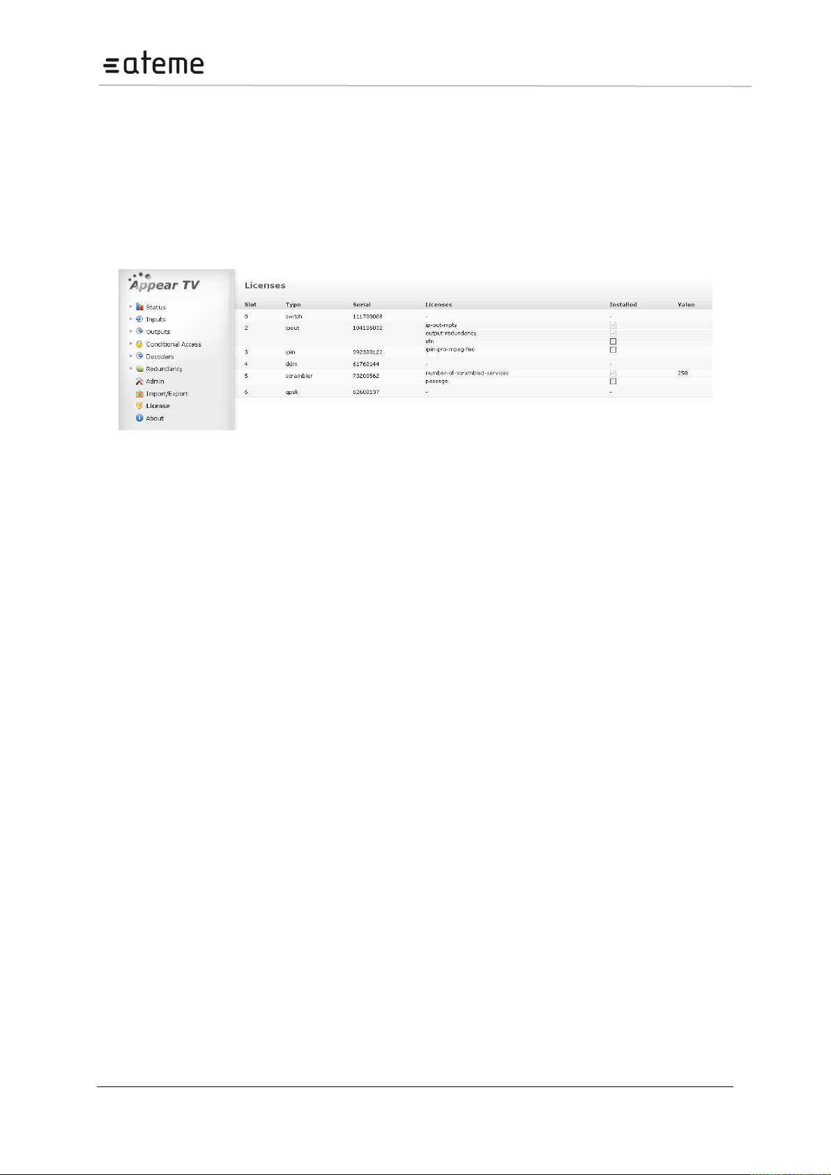
MC3x00 – User Manual
Table 1 - Types of Licenses available
If a licensed feature is used without the correct license installed, the system will produce a License
Violation warning. Use the License node to find which licenses are acquired and available.
4.3.1 Ordering a License File
Use the License node to order a license file. Flag the required licenses using the check boxes. The
Order License button will produce a license order file which should be sent to the vendor. A matching
license file will then be returned.
Figure 32 – Licensing
4.3.2 Installing a License File
A valid license file may contain licenses for one or several cards. This means that one license file may
be used for several units. The installation process will scan the file and if a matching serial number is
found the license will be installed on the respective card within the unit. The license file is signed; if
edited, it will be invalid.
Usually, the license file will be sent in a ZIP file and can be loaded directly to the GUI.
Once a license file is available from a machine with access to the web GUI, select the file and click
Install License. If no warnings are displayed, the additional privileges should now be available.
Page 38 / 213
Page 39
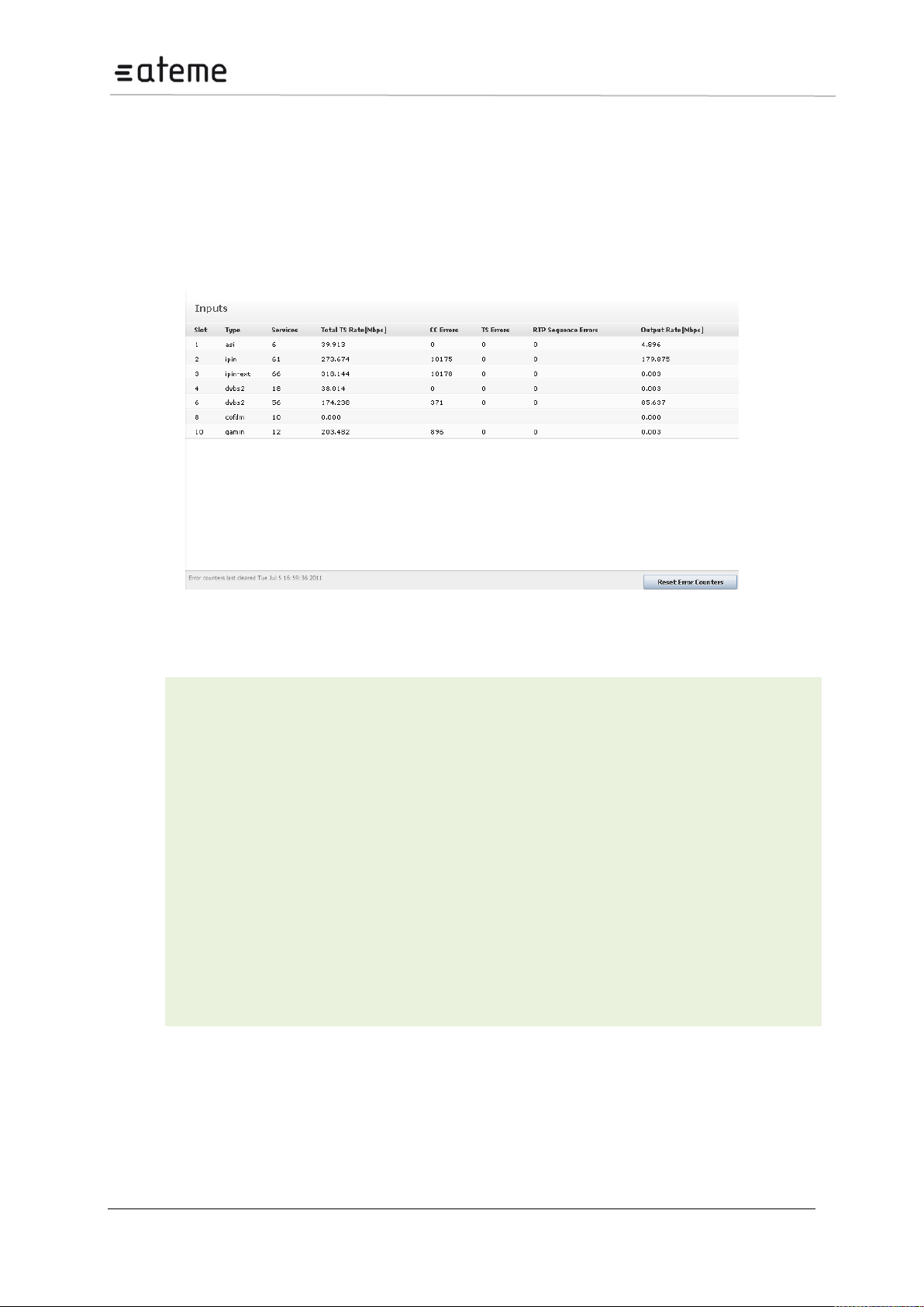
MC3x00 – User Manual
Slot
Slot position in the chassis
Type
Type of input module
Services
Number of services present in the transport stream
Total TS Rate
[Mbps]
Total bandwidth of the incoming transport stream
CC Errors
Number of Continuity Counter (CC) errors detected on all input ports since last reset;
CC errors indicate that one or more packets are lost.
TS Errors
Number of Transport Stream (TS) errors detected on all input ports. TS errors indicate
problems with the incoming TS structure of the streams
RTP
Sequence
Errors
Real-time Transport Protocol sequence errors since last reset (applies to IP only)
Output Rate
[Mbps]
Rate of active services transmitted to the backplane
5 Input Configuration
This chapter describes the Inputs node in the GUI and how to analyze the available inputs.
5.1 The Inputs Node
The unit can be configured to host a number of different input modules. Open the Inputs node from the
Navigation Pane to view all available input modules (Figure 5.1).
Figure 33 – Inputs Node
The following information is available in the Inputs node:
Each input module available in the unit has some common analysis features; they all support manual
definition of input PSI. The coming sections will describe these common features followed by details
on how each input module can be configured.
Page 39 / 213
Page 40
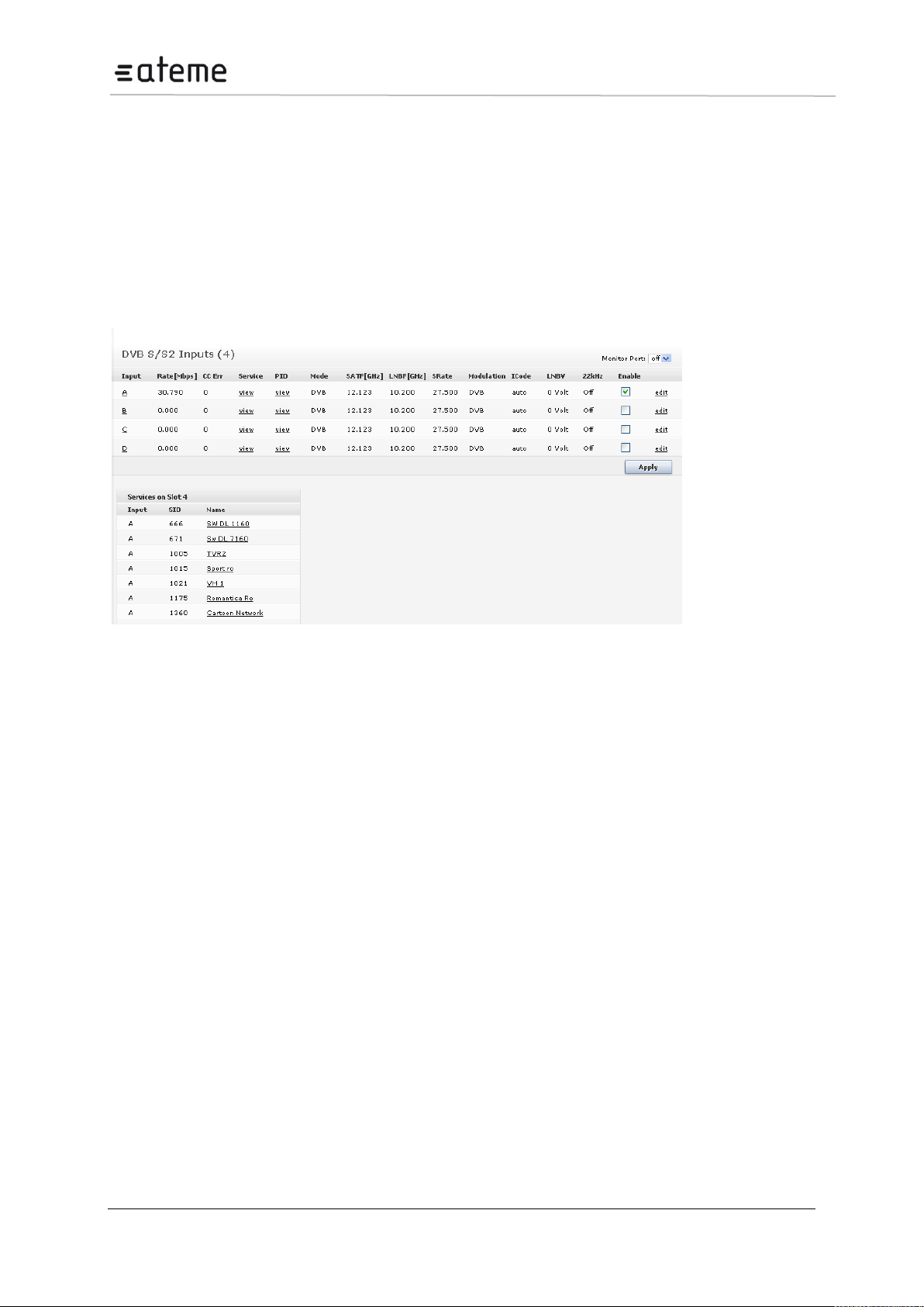
MC3x00 – User Manual
5.2 Input Analysis
For each input module the unit provides detailed MPEG/DVB/ATSC transport stream analysis for all
available input streams. The following information is provided by the input analysis engine:
Port specific status
PSI/SI analysis of all input services
PID display – listing all input PIDs for each input, with implicit highlighting of CC errors, PCR flag and
scrambling bits (odd/even)
This information is accessible by expanding the Inputs view in the Navigation Pane. The following
example (Figure 5.2) is based on a DVB-S/S2 input module, but the same applies to all input modules.
Figure 34 – Example of DVB-S/S2 Inputs
Page 40 / 213
Page 41
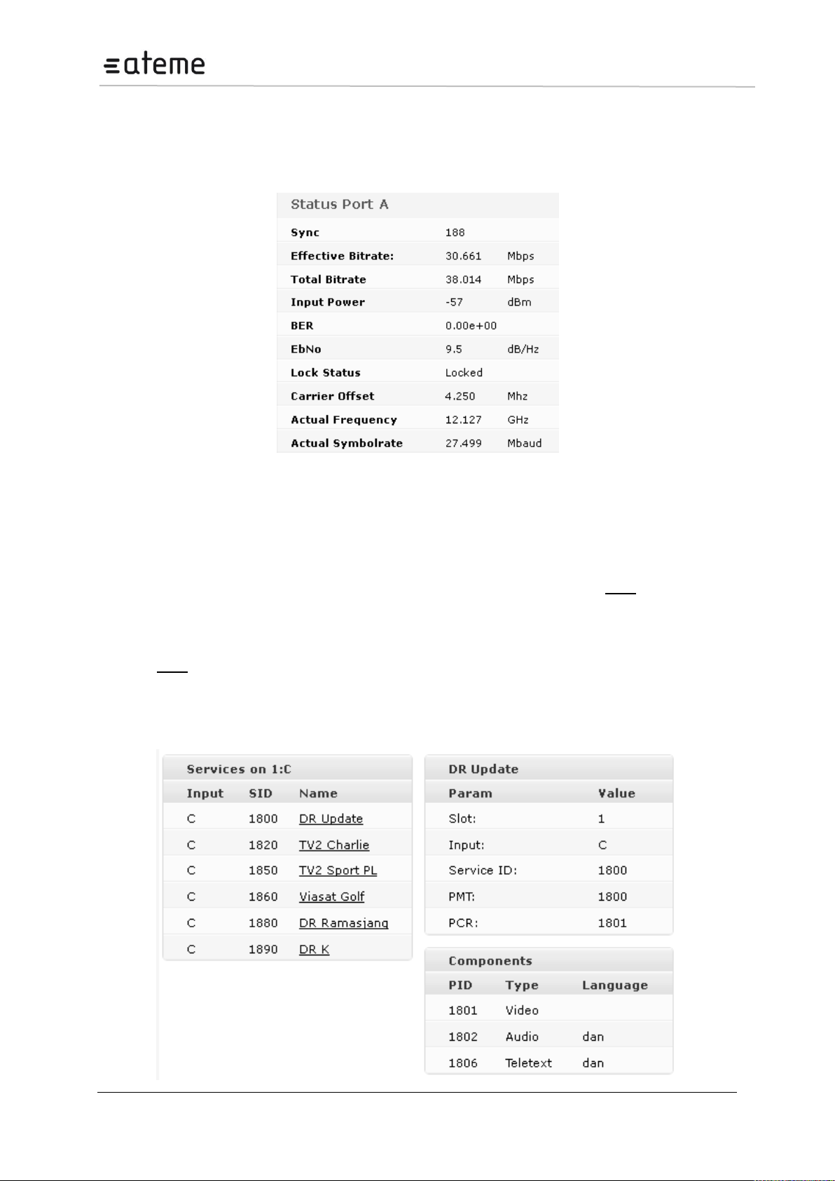
MC3x00 – User Manual
5.2.1 Input Port Analysis
Within the Inputs node, it is possible to access lower level information, e.g. port specific information.
To obtain port specific information for input modules with demodulators, click on the port letter in the
Input column.
Figure 35 – DVB-S/S2 Port Detailed View
For more details on actual parameters, refer to the configuration section for the respective input type in
this chapter.
5.2.2 Input Service Filtering and Analysis
It is possible to apply filters on information displayed in the GUI. Clicking on view in the Service
column for a selected multicast, results in only services associated with this multicast being displayed.
Clicking on one of the listed services will display more detailed information about the different PIDs like
PMT, PCR, video, audio, etc.
Click on view in the PID column for ASI inputs will display only PIDs associated with the selected
input. Simply choose any PID to obtain more detailed information.
To access detailed PSI/SI analysis of the input services, click the respective service in the lower pane.
The detailed analysis result will appear next to it, on the right.
Page 41 / 213
Page 42
MC3x00 – User Manual
Details of the PSI/SI analysis are not 100% DVB compliant, but it does include the most
commonly used tables and descriptors.
Figure 36 – Detailed PSI/SI Analysis of Input Services
The Audio language descriptor is decoded. In Figure above, the audio is listed as dan, ie Danish.
However, if no language descriptor is present the unit will auto-generate a descriptor for internal usage
and they will be named A01, A02, etc.
Page 42 / 213
Page 43
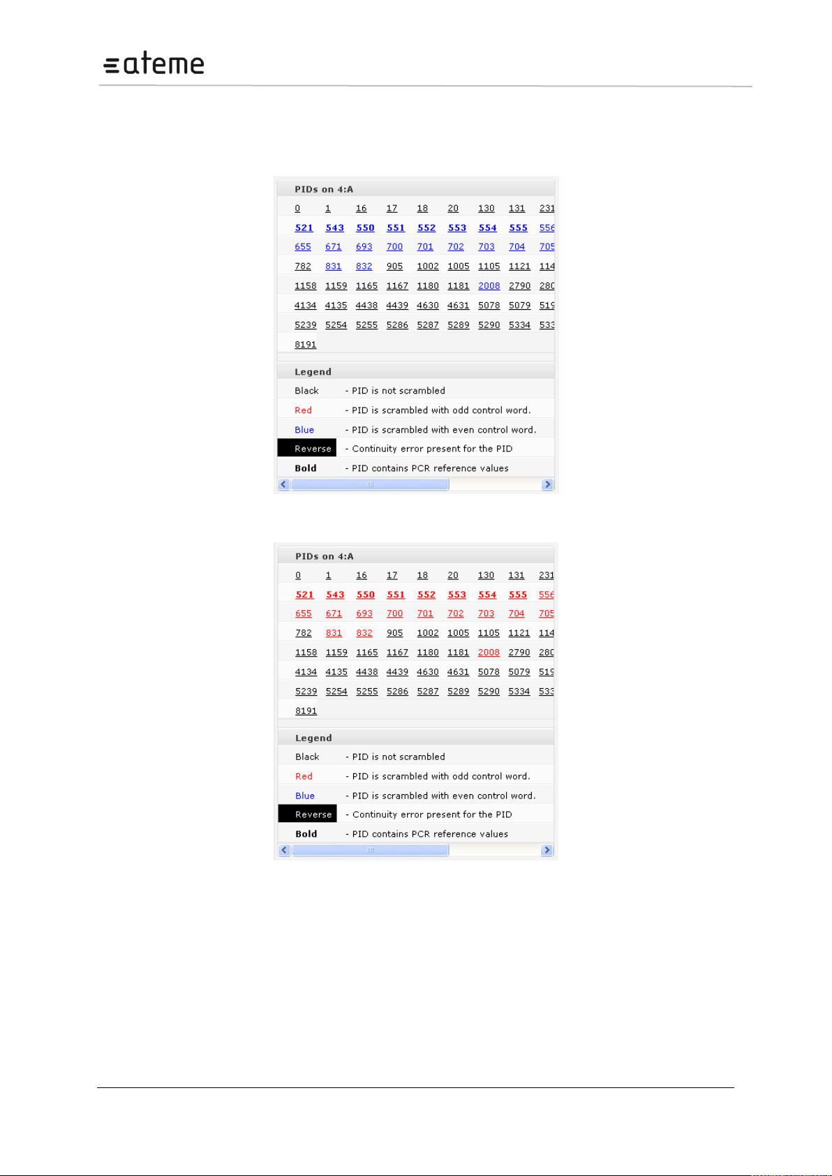
MC3x00 – User Manual
5.2.3 Input PID Analysis
The PID view lists all PIDs detected for a given port. This list is accessible via the PIDs column in the
top pane.
Figure 37 – PID Scrambled with Even Control Word
Figure 38 – PID Scrambled with Odd Control Word
For an input containing scrambled services the color of the scrambled PIDs will toggle between Blue
and Red as the ODD/EVEN bit toggles.
In Figures above we can for example see that PID 521:
is scrambled as it is colored,
contains PCR as it is bold and
no CC errors have occurred since none of the PID numbers are inverted in color.
It is possible to reset the CC error counters. This reset is a global operation for all inputs and is done
with the Reset CC button in the Inputs node.
Page 43 / 213
Page 44
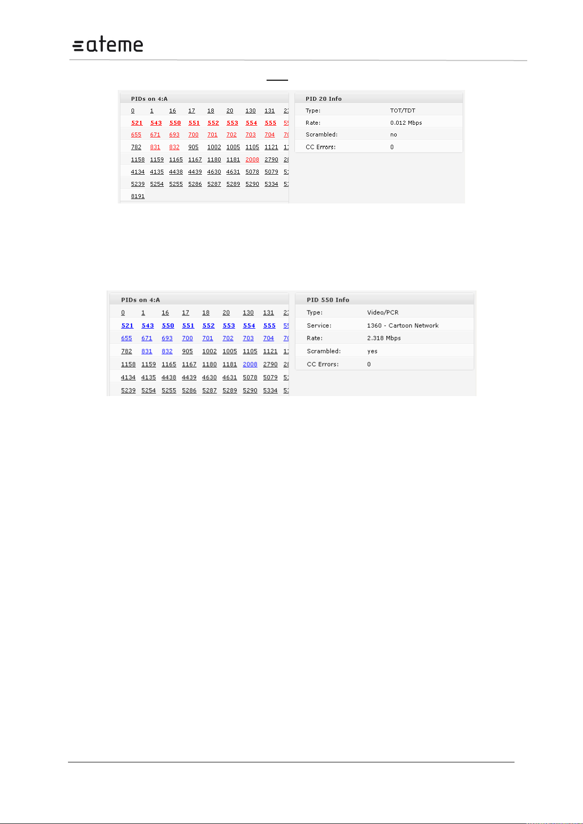
MC3x00 – User Manual
To obtain PID specific details, simply click on view in the PID column.
Figure 39 – Selecting PID 20
Selecting PID 20 (Figure 39 – Selecting PID 20), we see that it is a TDT PID. Also its bitrate and
number of CC errors are presented.
Selecting PID 550 gives a slightly different info as it is a video PID:
Figure 40 – Selecting PID 550
Page 44 / 213
Page 45
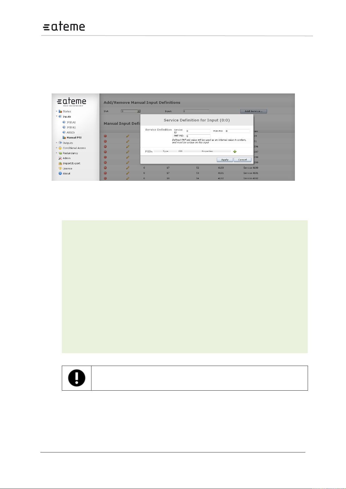
MC3x00 – User Manual
Service Id
Service ID for the manual service
PCR PID
PCR PID for the manual service
PMT PID
PMT PID for the manual service
Type
Select one of the following component types:
Video (MPEG-2)
H264
Audio (MPEG-2 audio)
AAC
AC-3
Private Sections
PES Private
Manual
PID
PID number for the component
Properties
Additional information for the component, if necessary.
The PMT PID may be defined with any value from 32 to 8190, but ensure that it is unique
in an MPTS configuration scenario. Also, if this input is part of an outgoing digital stream,
the PMT PID here is the PID value that will be assigned for the outgoing PMT.
5.3 Manual PSI
To manually define input PSI select Inputs > Manual PSI from the Navigation Pane.
In case the input PSI information is not available, a predefinition of the PSI is necessary in order to
configure a service that is occasionally available. This could be used, for instance, to predefine some
services for dynamic VOD usage.
Figure 41 – Manually define Input PSI
In the Manual PSI node, click Add Service and enter the appropriate values matching the incoming
stream. The following information is displayed:
Page 45 / 213
Page 46
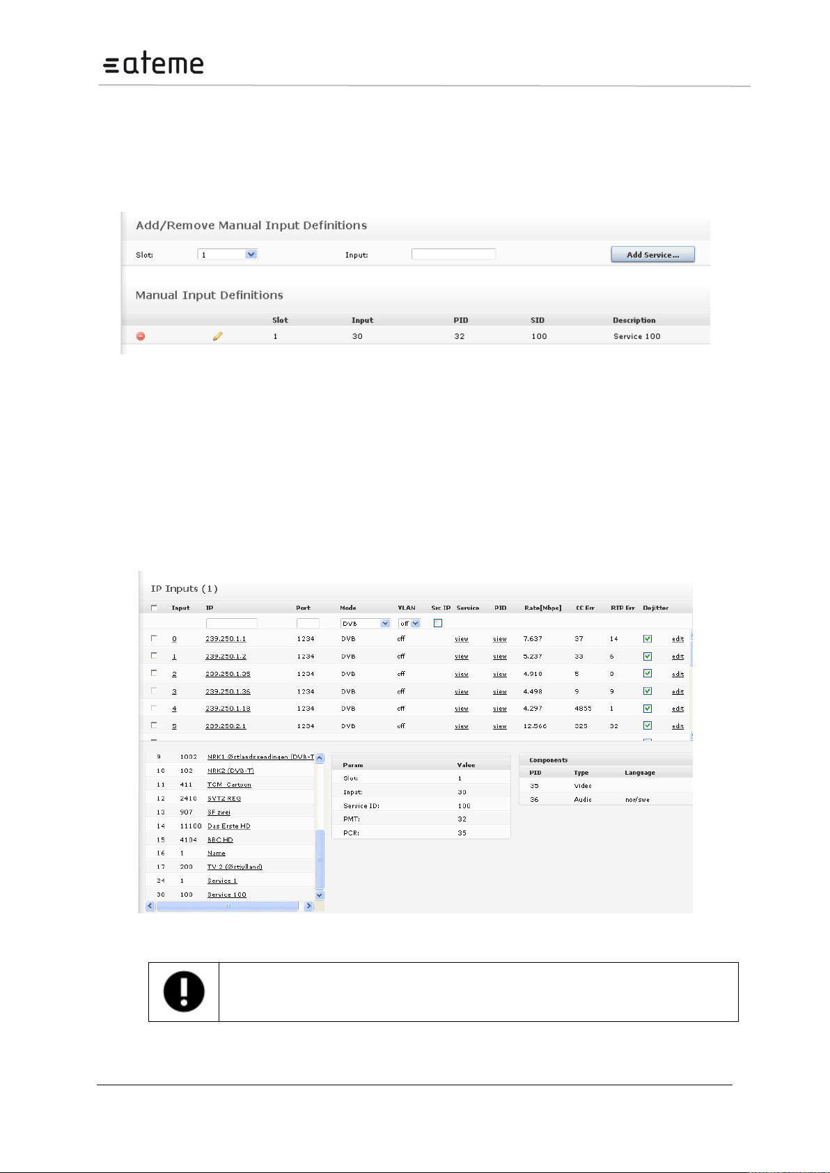
MC3x00 – User Manual
If manual PSI is defined for an input port, all incoming services must be defined. It is not
possible to define only one service manually and use the incoming PSI to represent the
rest.
When an input service is defined the following tables are generated:
PAT
PMT
All other table analysis is cancelled for this input port. The result is listed in the GUI (see Figure
below).
Figure 42 – Table Analysis when an Input Service is defined
This entry may be edited or deleted later using the corresponding icons on the left.
5.3.1 MPTS Support
If multiple services are defined for one input, they effectively represent a MPTS.
To check that the manually defined input has entered the system correctly, select the Inputs node and
ensure that the service information is present. In the example below (Figure 5.11 Service number 30
(under the Services panel) is represented with PSI even though the input has not yet been added to
the system.
Figure 43 – Verifying manually defined Inputs
Page 46 / 213
Page 47
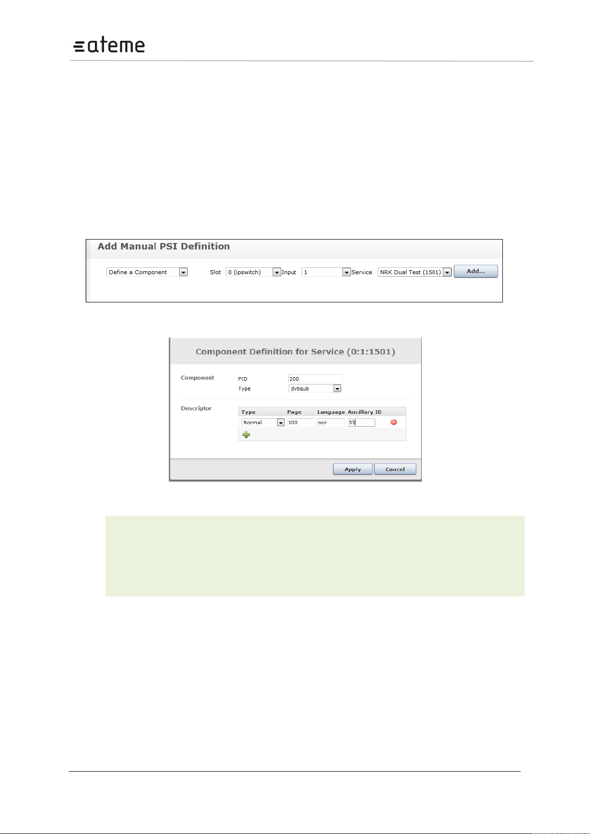
MC3x00 – User Manual
Component PID
Enter the PID value of the incoming PID to which the signaling shall be defined.
Component Type
Specify the type of component.
The Type defined here is the MC3x00 internal type.
Descriptor Type
Depending on the type of components different descriptor options will emerge.
5.3.2 PSI Modifications of input services
This PSI modification feature allows the user to modify existing incoming PSI, keeping the other PSI
information intact. The feature is currently implemented to solve two specific scenarios:
Add signaling to incoming “DVB Subtitling” and “EBU teletext” components in PMT. Other component
types can also be added but without any descriptors only.
Change audio language descriptor of an incoming audio component.
5.3.3 Defining a component type for an incoming PID.
To define the PSI for an incoming PID
Select the input reference from the Input->PSI navigation Page.
Press the Add button and insert the appropriate information.
Figure 44 – Defining Manual PSI
Figure 45 – Defining component for service
Page 47 / 213
Page 48
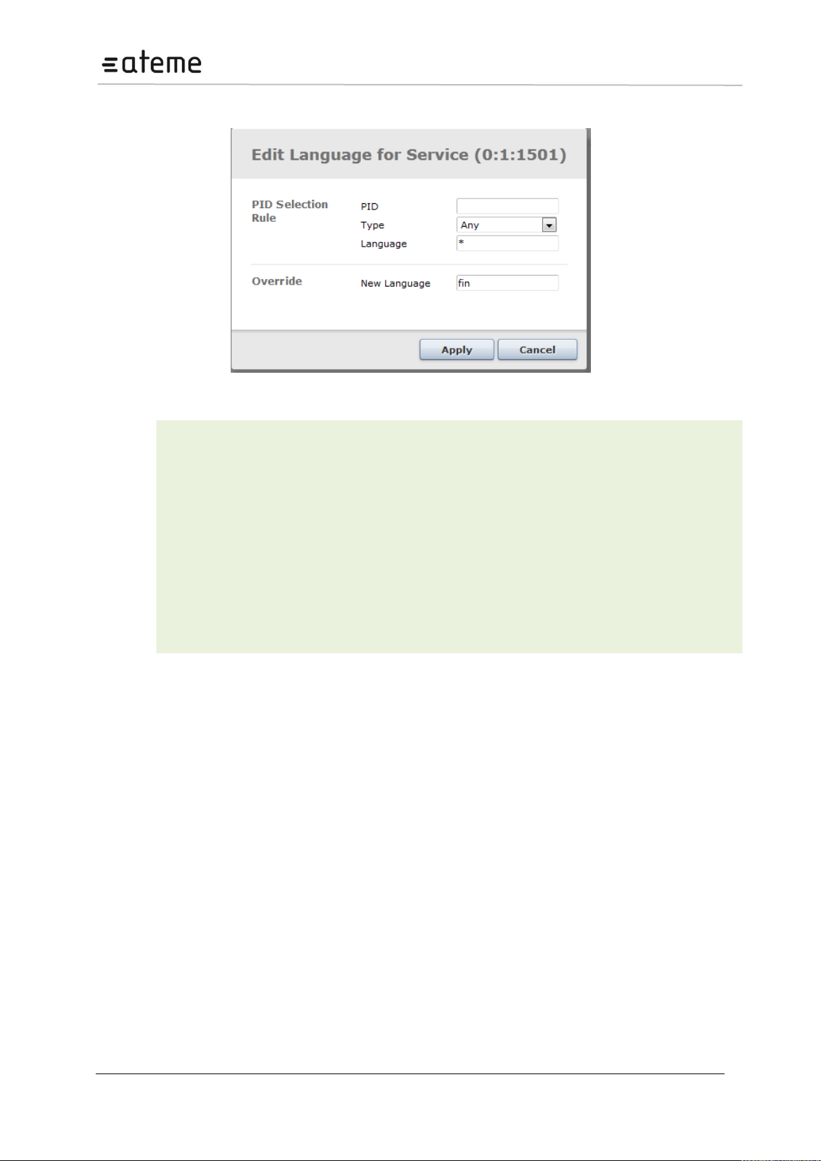
MC3x00 – User Manual
PID
The input pid to update.
Not mandatory
Type
The audio type where the language descriptor shall be replaced.
mpeg-audio
ac-3
aac_latm
aac_adts
e-ac3-e
Not mandatory
Language
The language signaled on the input. If this is not a filtering criteria
then use wildcard “*”
Not mandatory
Override
The new language descriptor to be used for the incoming
component.
Mandatory
5.3.4 Changing the language descriptor of an incoming audio
Figure 46 – Edit Language descriptor
Note
If several PIDs are matching the input filtering criteria’s, then the signaling for all these components
will be updated.
If the input signaling is dual mono, and no Language (source) is specified, then the right channel
descriptor will be replaced.
Page 48 / 213
Page 49
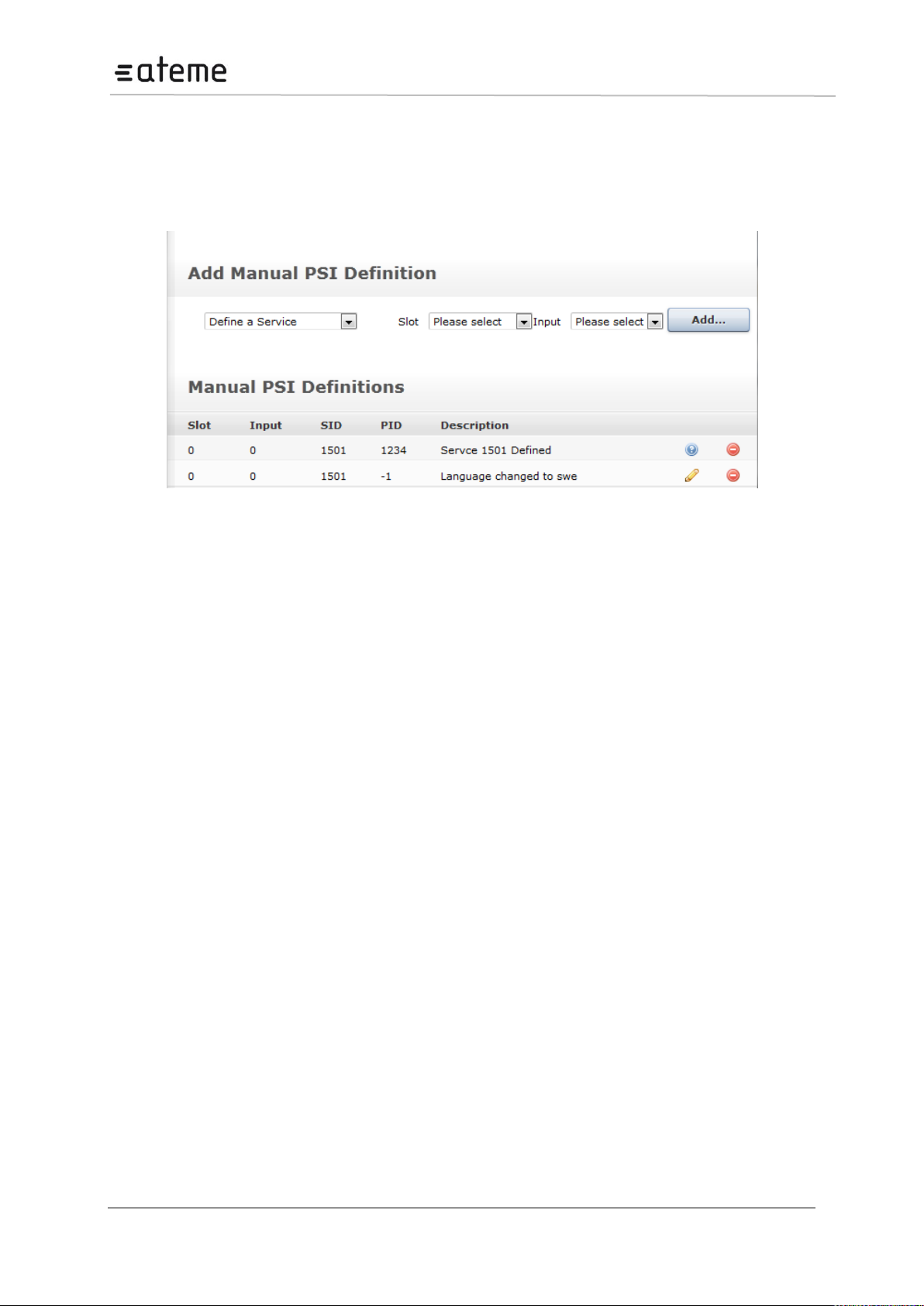
MC3x00 – User Manual
5.3.5 Edit options on existing manual PSI
Under the Manual-PSI node all current manual PSI rules will be listed. Not all rules can be changed
once they are defined. These are indicated with a blue circle with the “?” mark. To change these
components they need to be removed and re-added. The rules indicated with a pencil can be changed
without remove/Add operation.
Figure 47 – Editing existing Manual PSI
5.4 DVB-S/S2 Input
The DVB-S/S2 module supports both DVB-S and DVB-S2 inputs. The DVB-S2 functionality is licensed
and will only be visible in the GUI if a correct license is installed for the module.
The hardware revision 2.0 DVB-S/S2 input module includes a new advanced DVB-S2 demodulator.
This new DVB-S2 input card is compatible with the old DVB-S/S2 input card. The hardware revision of
the module is available on the About page in the web GUI.
In addition to the standard DVB-S2 this new card supports
16_APSK and 32_APSK mode.
Multistream input
Auto modulation detection mode.
Each DVB-S/S2 module can receive up to four individual L-Band satellite input streams. To configure
the module:
Switch to the Inputs node in the Navigation Pane
Select DVB S/S2 to display the module configuration (see Figure below). Services available on all four
input ports will be listed in this view.
Page 49 / 213
Page 50

MC3x00 – User Manual
Input
Port on the DVB-S/S2 input module
Rate [Mbps]
Incoming data rate
CC Err
Continuity Counter Error – indicates that one or more packets are lost
Mode
PSI/SI Analysis mode.
SATF [GHz]
Satellite Frequency
SRate
Symbol Rate – specify the symbol rate of the incoming DVB-S/S2 signal. The
demodulator’s range is 950 – 2150 MHz.
Modulation
Select one of the following modes:
Auto (only for HW Rev. 2.0)
DVB-S
DVB-S/S2_QPSK
DVB-S/S2_8PSK
DVB-S/S2_16APSK (only for HW Rev. 2.0)
DVB-S/S2_32APSK (only for HW Rev. 2.0)
ICode
Inner Code – specify the FEC overhead fraction
LNBV
LNB Voltage – select the output voltage from the dropdown box
22kHz
Switch the 22kHz output signal on or off
Enable
Enable the corresponding input port
Figure 48 – DVB-S2 Input
The DVB-S/S2 node shows all major configuration settings as well as the current bitrate and service
information. The following parameters are available:
The above list of parameters can be configured by clicking on the edit link to the right of each input.
The pop up dialog below will be displayed:
Page 50 / 213
Page 51
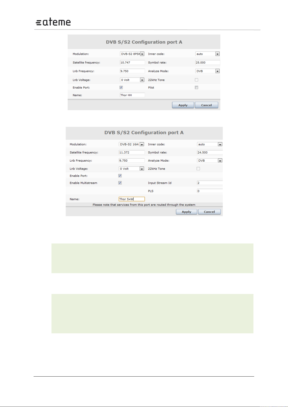
MC3x00 – User Manual
Pilot
Activates the use of distributed pilot symbols (of the DVB-S/S2 standard) for fine
frequency estimation and for detection of the presence of strong phase noise.
Name
This parameter allows for each port in a module to be labeled. This label is visible as a
tooltip when the mouse cursor hovers over the port.
Enable
Multistream
Enable the Multistream
Input Stream ID
Multistream Input Stream ID. Note it is only possible to tune into one Stream ID
PLS
Multistream PLS (Physical Layer Scrambling). PLS is often referred to as the gold
code and will be provided by your content provider if required. Default value is 0
Figure 49 – Edit DVB-S/S2 Port Configuration
Figure 50 – Edit DVB-S/S2 (HW Rev. 2.0) Port Configuration
In this dialog, additional parameters can also be modified:
In addition to these parameters, card with hardware revision 2.0 will also have the following options:
To monitor any of the demodulated DVB-S/S2 input signals, one of the DVB-S/S2 input ports can be
assigned to the output ASI monitor interface. The demodulated DVB-S/S2 input signal will then be
copied onto the monitor port for further analyzing or monitoring of the transport stream. Normal
operation will not be affected if the monitoring port is used.
Page 51 / 213
Page 52
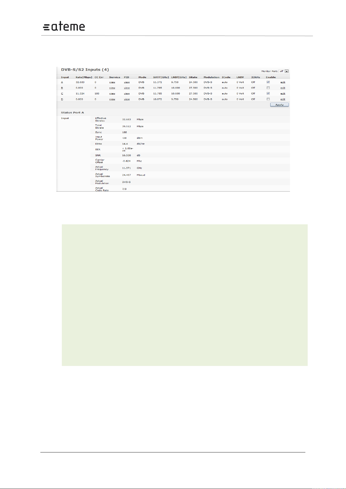
MC3x00 – User Manual
Sync
MPEG sync number: 188 or 204
Effective Bitrate
Effective bitrate of the input stream
Total Bitrate
Total bitrate of the input stream
Input Power
Input power for the DVB-S/S2 signal in dBm
EbNo
Energy per bit/(Noise per 1Hz BW)
BER
Bit Error Rate
SNR
Signal to Noise Radio, indicated in dB
Carrier Offset
Carrier offset
Actual Frequency
Frequency reported by the demodulator
Actual Symbolrate
Symbol rate reported by the demodulator
Actual Modulation
Modulation reported by the demodulator
Lock Status
Lock status of the tuner
Refer to the general input analysis description at the start of this chapter to analyze the input. Click on
the letter representing the input channel (A, B, C or D) to display the status parameters for the specific
input port. The resulting display is shown in Figure below.
Figure 51 – DVB-S/S2 Status View
The following information is displayed:
The status parameters EbNo and SNR will be 0 when the tuner is not locked.
Page 52 / 213
Page 53
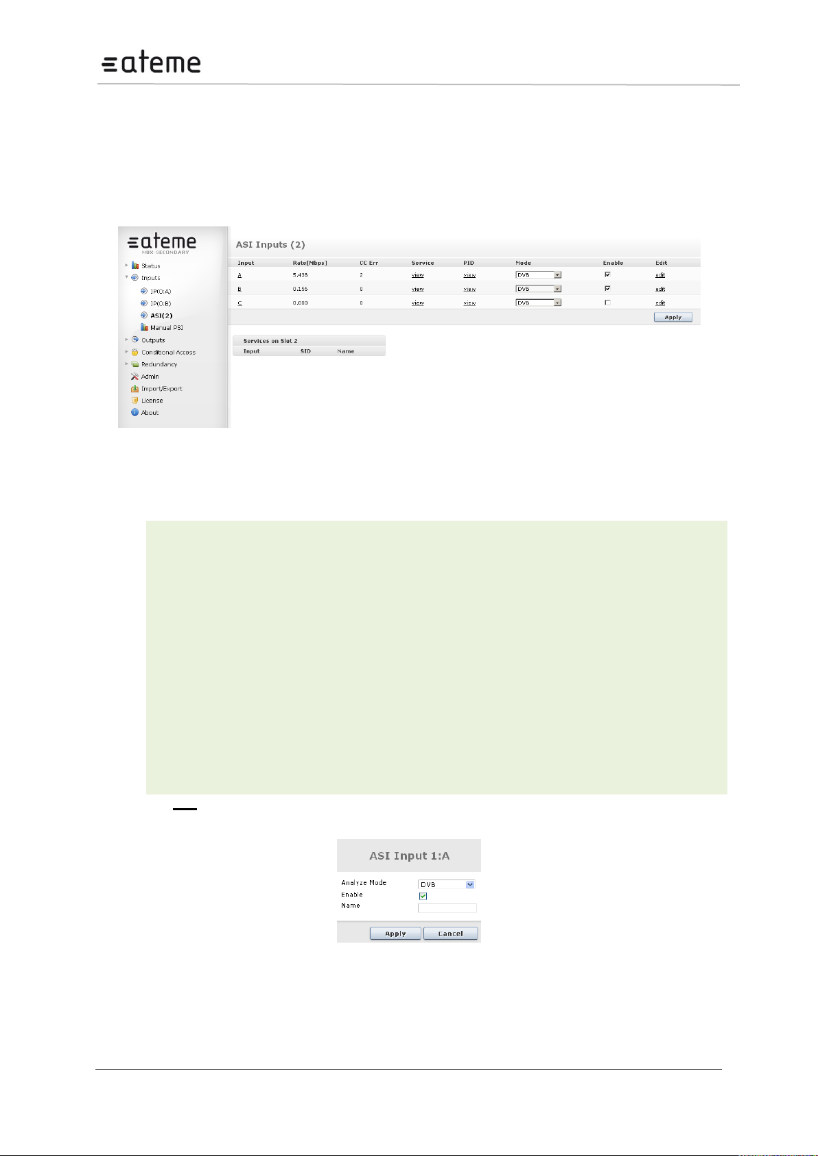
MC3x00 – User Manual
Input
Port on the ASI input module
Rate [Mbit/s]
Incoming data rate
CC Err
Continuity Counter Error – indicates that one or more packets are lost
Mode
Select one of the following modes:
DVB
DVB (SDT)
MPEG
ATSC
OFF
The default mode is DVB. If the incoming transport stream is not DVB compliant,
use MPEG mode instead.
Enable
Enable the corresponding input port
5.5 ASI Input
The ASI input module can receive up to three/four individual ASI input streams depending on the
hardware revision. Each ASI input can support up to 213Mbit/s. To configure the module:
Switch to the Inputs node in the Navigation Pane
Select the ASI module you want to configure to display the module configuration. Services available on
all three ASI input ports will be listed in this view.
Figure 52 – ASI Input
The ASI node shows all configurable settings as well as the current bitrate and service information.
The following parameters are available:
Clicking the edit link on the right displays the dialog below, allowing for the Mode, Enable, and Name
parameters to be edited.
Figure 53 – ASI Edit Dialog
Page 53 / 213
Page 54
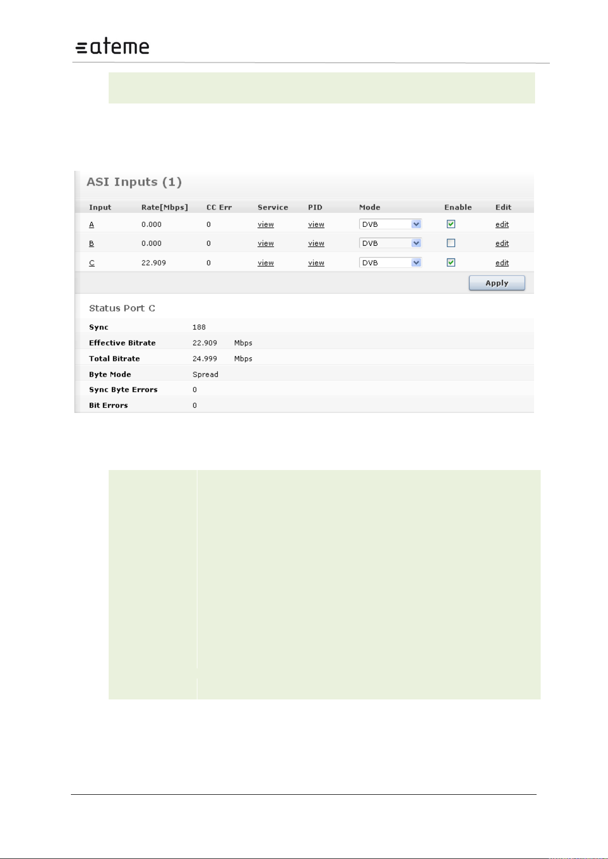
MC3x00 – User Manual
Name
This parameter allows for each port in a module to be labeled. This label is visible as
a tooltip when the mouse cursor hovers over the port.
Sync
MPEG sync number: 188 or 204
Effective Bitrate
Effective bitrate of the input stream
Total Bitrate
Total bitrate of the input stream
Byte Mode
The byte mode specifies how the TS data is transported over the ASI link.
Burst Mode – All TS data bytes are sent without any idle symbols in between
Spread Mode – The SI specification requires at least one idle byte between each
data byte, and each packet start indicator (0x47) is preceded with at least two idle
bytes. The ASI output stream in Spread Mode guarantees that each data byte is
preceded with two idle symbols. This effectively reduces the maximum data rate to
1/3 of the maximum ASI output rate, i.e. (213/3) Mbps. If higher rates are required,
use Burst Mode.
Sync Byte
Errors
Number of sync byte errors on the incoming stream
Bit Errors
Number of bit errors on the incoming stream
The status parameters for the ASI module are shown in the figure below. Click on the letter
representing the input channel (A, B or C) to display the status parameters for the specific input port.
The resulting display is shown in figure below.
Figure 54 – ASI Status View
The following information is displayed:
Page 54 / 213
Page 55
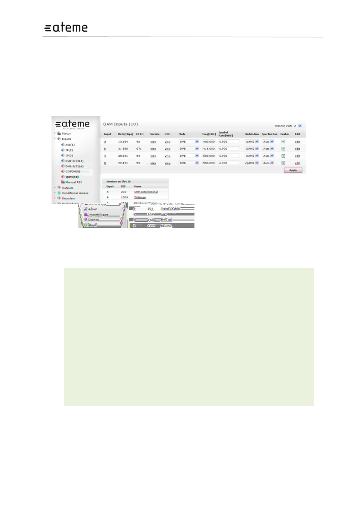
MC3x00 – User Manual
Input
Port on the QAM input module
Rate [Mbps]
Incoming data rate
CC Err
Continuity Counter Error – indicates that one or more packets are lost
Mode
Select one of the following modes:
DVB
DVB (SDT)
MPEG
ATSC
OFF
The default mode is DVB. If the incoming transport stream is not DVB
compliant, use MPEG mode instead.
Freq [MHz]
Specify the QAM frequency in MHz, valid range is 170k – 887Mhz
Symbol Rate
[MBd]
Specify the Symbol Rate in MBd, valid range is 0.452 – 7.23 MBd
5.6 QAM/DVB-C Input
The QAM/DVB-C input module can receive up to four individual QAM frequencies. The QAM/DVB-C
input modules comes in 2 HW versions; a 2 slot version referred to as QAM input and a 1 slot version
referred to as DVB-C input. To configure the module:
Switch to the Inputs node in the Navigation Pane
Select the QAM module you want to configure and the module configuration window will be displayed
(see Figure below). The services available on all four QAM input ports will be listed in this view.
Figure 55 – QAM Input
The QAM/DVB-C input window shows all configurable settings as well as the current bitrate and
service information. The following parameters are available:
Page 55 / 213
Page 56
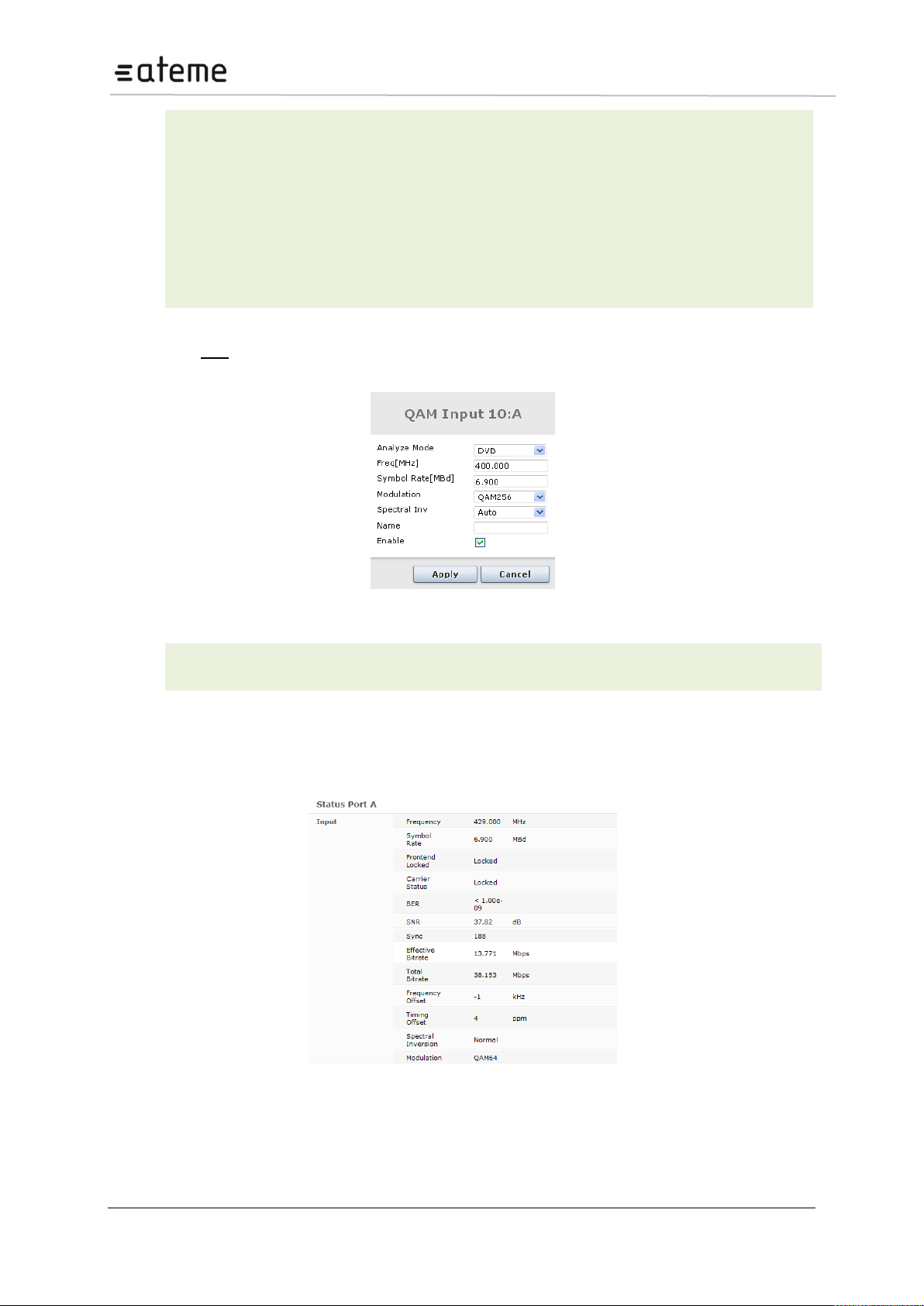
MC3x00 – User Manual
Modulation
Specify the type of modulation, select from one of the following:
QAM16
QAM32
QAM64
QAM128
QAM256
Spectral Inv
Specify the Spectral Inversion, choose from Auto, Normal, or Inverted
Enable
Enable the corresponding input port
Name
This parameter allows for each port in a module to be labeled. This label is visible as
a tooltip when the mouse cursor hovers over the port.
Clicking the edit link on the right displays the dialog below, allowing for the Mode, Freq [MHz],
Symbol Rate [MBd], Modulation, Spectral Inv, Name, and Enable parameters to be edited.
Figure 56 – QAM Edit Dialog
The status parameters for the QAM module are shown in the figure below. Click on the letter
representing the input channel (A, B, C or D) to display the status parameters for the specific input
port.
Figure 57 – QAM Status View'
Page 56 / 213
Page 57

MC3x00 – User Manual
Sync
MPEG sync number: 188 or 204
Effective Bitrate
Effective bitrate of the input stream
Total Bitrate
Total bitrate of the input stream
Frequency
Currently tuned frequency in MHz
Symbol Rate
Symbol Rate in MBd
Modulation
Modulation of the currently tuned channel
BER
Bit Error Rate
SNR
Signal to Noise Ratio
State
Current state – possible values are:
Not Initialised
Initialised
Tuning
Scanning
Idle
Unknown
Carrier Status
Status of the tuning process
Frontend
Locked
Lock status of the tuner
Frequency Offset
The value of frequency offset is in KHz, will depend on the input stream.
Timing Offset
The Value of timing offset is in ppm, will depend on the input stream.
Spectral Inv
The Spectral Inversion can be from Auto, Normal, or Inverted.
The following information is displayed:
Additional parameters for DVB-C Input card (1 slot version).
Page 57 / 213
Page 58
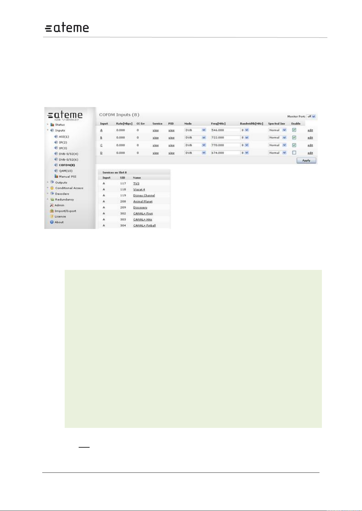
MC3x00 – User Manual
Input
Port on the COFDM input module
Rate [Mbps]
Incoming data rate
CC Err
Continuity Counter Error – indicates that one or more packets are lost
RF Freq [MHz]
Specify the COFDM frequency in MHz, valid range is 47 – 862Mhz.
Bandwidth [MHz]
Specify the bandwidth, select from 6, 7, or 8MHz
Spectral Inv
Specify the Spectral Inversion, choose from Auto, Normal, or Inverted
Mode
Select one of the following modes:
DVB
DVB (SDT)
MPEG
ATSC
OFF
The default mode is DVB. If the incoming transport stream is not DVB
compliant, use MPEG mode instead.
Enable
Enable the corresponding input port
5.7 COFDM/ DVB-T Input
The COFDM / DVB-T input module can receive up to four individual COFDM frequencies. The
COFDM/DVB-T input modules comes in 2 HW versions; a 2 slot version referred to as COFDM input
and a 1 slot version referred to as DVB-T input. To configure the module:
Switch to the Inputs node in the Navigation Pane
Select the COFDM module you want to configure and the module configuration window will be displayed
(see Figure ). Services available on all four COFDM input frequencies will be listed in this view.
Figure 58 – COFDM Input
The COFDM / DVB -T input window shows all configurable settings as well as the current bitrate and
service information. The following parameters are available:
Clicking the edit link on the right displays the dialog below, allowing for the Mode, Freq [MHz],
Symbol Rate [MBd], Bandwidth [MHz], Spectral Inv, Enable, and Name parameters to be edited.
Page 58 / 213
Page 59
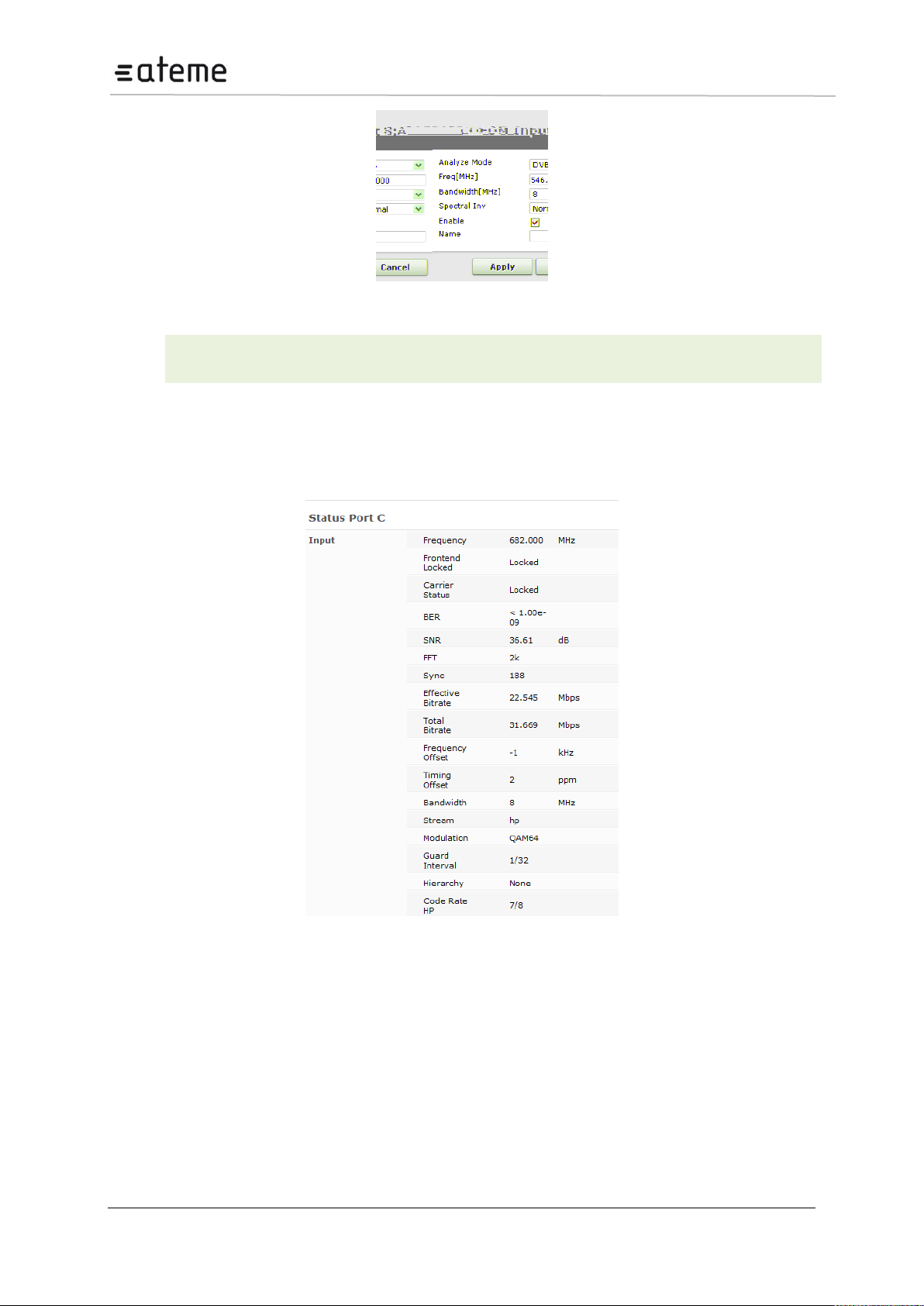
MC3x00 – User Manual
Name
This parameter allows for each port in a module to be labeled. This label is visible as a
tooltip when the mouse cursor hovers over the port.
Figure 59 – COFDM Edit Dialog
The status parameters for the COFDM module are shown in
Figure 5.24 below. Click on the letter representing the input channel (A, B, C or D) to display the status
parameters for the specific input port.
Figure 60 – COFDM Status View
Page 59 / 213
Page 60

MC3x00 – User Manual
Sync
MPEG sync number: 188 or 204
Effective Bitrate
Effective bitrate of the input stream
Total Bitrate
Total bitrate of the input stream
Frequency
Currently tuned frequency in MHz
Frequency Offset
Offset between the configured frequency and the actual lock in kHz
Bandwidth
Bandwidth of the currently tuned channel
Spectral Inversion
Current spectral inversion, Normal or Inverted
Modulation
Modulation of the currently tuned channel
Guard Interval
Guard Interval of the currently tuned channel
FFT
Current FFT size of the downstream signal
BER
Bit Error Rate – represents the amount of bits that have errors in relation to the
total number of bits received in transmission. The BER is usually expressed in
ten to a negative power. (The value displayed is prior to Viterbi corrections.)
CBER
Channel Bit Error Rate is the Bit Error Rate post Viterbi corrections, indicating
strength and quality of the original signal.
SNR
Signal to Noise Ratio – represents how much the signal has been corrupted by
noise.
Power Level
Power level of the COFDM input signal. This value refers to the COFDM
module’s power level, not the input power level.
State
Current state – possible values are:
Not Initialised
Initialised
Tuning
Scanning
Idle
Unknown
Carrier Status
Status of the tuning process
Frontend Locked
Lock status of the tuner
Timing Offset
The value of timing offset is in ppm, will depend on the input stream.
Stream
Input Stream.
Hierarchy
Hierarchy of the currently tuned channel.
Code rate
Code rate of the currently tuned channel.
Additional parameters for DVB-T Input card (1 slot version).
Page 60 / 213
Page 61

MC3x00 – User Manual
Page 61 / 213
Page 62
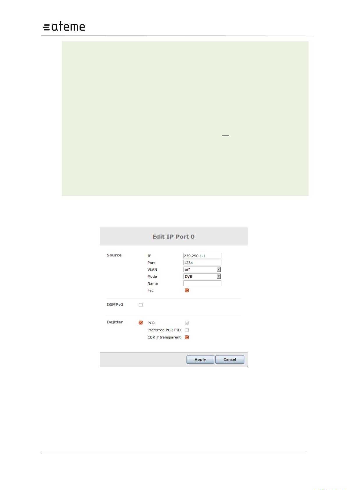
MC3x00 – User Manual
Input
Port on the IP input module – assigned automatically when joining a unicast or
multicast.
For Switch with IP modules, the Port A will use input numbers 0 to 249, Port B will use
input 1000 to 1249.
IP
IP address of the multicast or unicast
Port
Port of the multicast or unicast
Rate [Mbps]
Incoming data rate
CC Err
Continuity Counter Error – indicates that one or more packets are lost
RTP Err
Real-time Protocol Error – represents the number of discontinuities on the RTP
counter if RTP is enabled on source. If RTP is not enabled on the source, N/A is
displayed.
Mode
The mode of the input stream.
De-Jitter
Checking this check box activates the de-jitter algorithm on the input port. Enabling
this algorithm is recommended in order to achieve the best results. However, in some
cases, if the input quality is very poor or missing PCR PID, a better result may be
achieved by disabling this feature. Note that the output from the streamer will be very
poor as well.
For IP input modules, clicking on the IP address under the IP column allows for the IP, Port, Mode,
Dejitter, Name, IGMPv3, and VLAN parameters to be edited.
Figure 62 – Edit IP Port
Page 62 / 213
Page 63
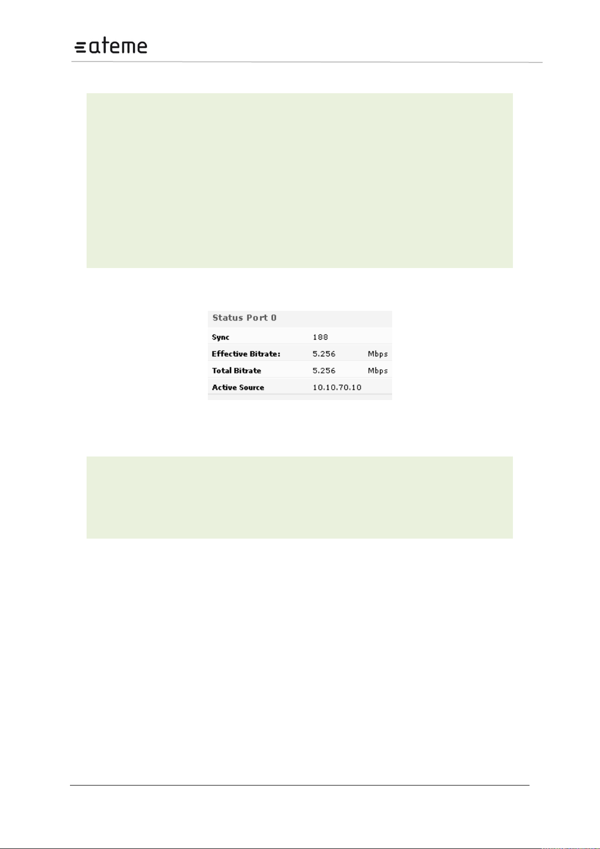
MC3x00 – User Manual
Name
This name is displayed as a tooltip when the mouse cursor hovers over the port.
IGMPv3
Enable or disable IGMPv3 on the port, Please see 5.8.1 for more information and
options
Dejitter
If input de-jittering is enabled, the following options are displayed:
PCR. This is automatic for regular streams
Preferred PCR PID. This allows you to set a PCR PID in the input multiplex
as a priority to use for de-jittering. If this PID is not available, then the next
valid detected PCR will be used. This is only valid for transparently mapped
streams.
CBR (if transparent). This de-jitter mechanism will use the incoming CBR
total bitrate as a guide for the clock source of the stream. This is only valid
for transparent mapped and PID imported outputs.
This feature is only available on the Switch+IP module.
Sync
Interval of the sync byte, usually 188
Effective Bitrate
Effective bitrate of the input stream
Total Bitrate
Total bitrate of the input stream
Active Source
IP address for the MPTS/SPTS source (Used for IGMP v3)
The following additional parameters are available for configuration:
The status parameters for the IP module are shown in Figure below.
Figure 63 – IP Input Port Status
The following parameters are available:
5.8.1 Setup of IPv6 input
In the 3.8 software The Switch+IP input module now supports IPv6 multicast and unicast inputs. When
using standard IPv6 address syntax (128 bits, ‘:’ instead of ‘.’), the GUI will interpret the address as an
IPv6 address.
The VLAN setup is independent on the choice of IPv4 or IPv6.
Source IP address has to match the IP format used for the destination IP address.
Note that IPv6 will use MLD for requesting multicasts. IGMP is used only for IPv4. For source filtering
the “IGMPv3” field has changed name to “IGMPv3/SSM” to cover both modes. SSM = “Source
Specific Multicast”.¨
Modification of input
Page 63 / 213
Page 64
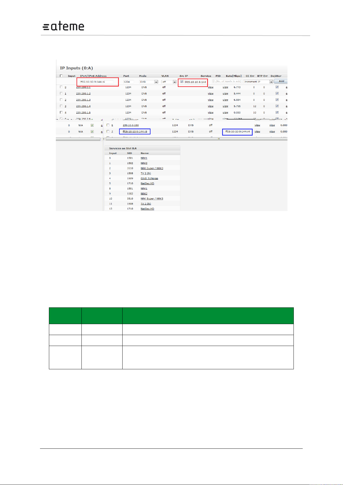
MC3x00 – User Manual
Sources
Source
filter
Comment
0
Off
GUI has not enabled IGMPV3 and no source is specified.
1
On
A single IGMPV3 source.
>1
Off
In this mode all sources are mapped to the same port. I.e. it is not
possible to reuse the MCAST:PORT pair on other inputs
Please note, only one of these sources should be active at a given time.
The defined inputs may be modified to use another IP address. The new IP address may be chosen
freely between IPv4 and IPv6 addresses.
Figure 64 – Setup of IPv6 input
5.8.2 IGMP Source filtering on Switch IP input.
In IGMPV3 the source address is part of the protocol. I.e. it is possible to join the same multicast from
specific sources. In this case, only multicasts from the specified source(s) are subscribed to. This
requires that the network uses IGMP v3. When enabled, the source filtering is at the IP level, which
only allows incoming data from a single specified source. Since this is at the IP level, it works
regardless of IGMP version.
Source filtering (relevant where 1 source is specified) is only available in Switch+IP input cards.
System behavior for different combinations of IGMP (version 2 or 3) input configurations:
Page 64 / 213
Page 65
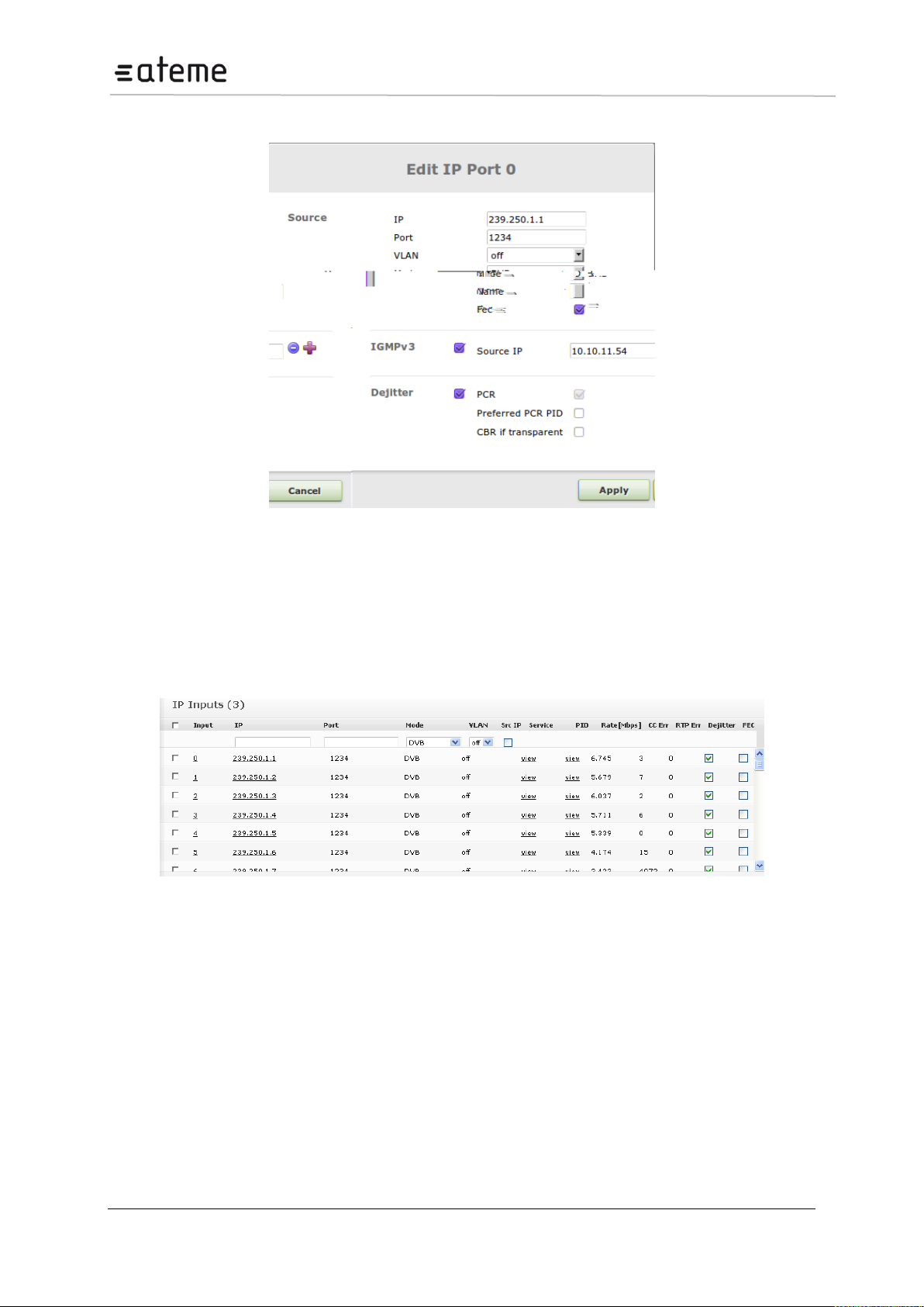
MC3x00 – User Manual
IGMP Source filtering is shown in figure below
Figure 65 – Edit IP Port for IGMP source filtering
If it is required that multiple sources of the same multicast be enabled concurrently, then these will
need to be subscribed to on unique input ports, each specifying their source IP address.
5.8.3 IP Input with FEC
For IP input modules with FEC, the input window has an additional column with a checkbox for each
stream, allowing you to enable FEC.
Figure 66 – IP Input Page (for Modules with FEC)
For the IP input module with FEC there are additional status parameters are available, on top of the
generic Sync, Effective Bitrate, Total Bitrate, and Active Source, as shown in Figure below.
Page 65 / 213
Page 66
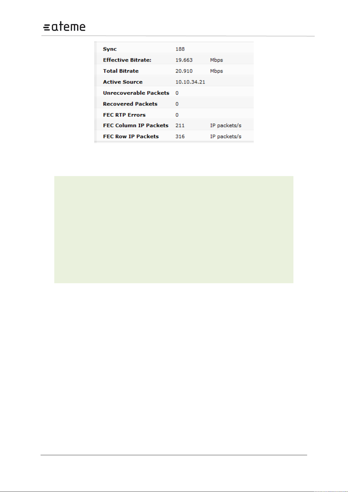
MC3x00 – User Manual
Unrecoverable
Packets
Number of lost data packets that cannot be recovered with FEC
Recovered Packets
Number of data packets recovered with FEC
FEC RTP Errors
Number of missing FEC packets
FEC Column IP
Packets
Number of Column FEC packets per second (packet rate)
FEC Row IP Packets
Number of Row FEC packets per second (packet rate)
FEC Matrix Rows
(D)
Number of rows in the FEC matrix of the incoming stream
FEC Matrix Columns
(L)
Number of columns in the FEC matrix of the incoming stream
Figure 67 – IP Input Port Status (for Modules with FEC)
The additional parameters are described in further detail below:
The combination of Unrecoverable Packets, Recovered Packets, and FEC RTP Errors is a good
indication of network quality.
5.8.4 Adding a New Input Stream
In the Input Control pane add the multicast/unicast IP address and port. Click Add. The input module
will now issue an IGMP join request for the selected multicast and start to analyze the incoming
stream. The service found on the selected multicast will be listed in the service view in the lower part
of the input page.
5.8.5 Removing a Multicast Input
Select the input to be removed by clicking on the check box on the left of the input entry (in the
Existing IP Inputs pane).
Click the Remove button in the Remove section to remove a selected input.
Please note that you can only remove inputs that are currently not in use. To delete these streams, the
associated output service must first be removed/disabled.
Page 66 / 213
Page 67
MC3x00 – User Manual
Currently IP Input seamless module does not support VLAN inputs
Slot
Module
Slot position in the chassis
A and B both will be displayed.
Type
Type of input module : ipswitch
Services
Input Rate
Number of services present in the transport stream
Input Rate of active services for both A and B will be displayed.
Effective Rate
Total bandwidth of the incoming transport streams.
CC Errors
Number of Continuity Counter (CC) errors detected on all input ports
since last reset; CC errors indicate that one or more packets are lost.
TS Errors
Number of Transport Stream (TS) errors detected on all input ports. TS
errors indicate problems with the incoming TS structure of the streams
RTP Errors
Real-time Transport Protocol sequence errors since last reset (applies to
both Port A and port B)
BP Rate
Rate of active services transmitted to the backplane
5.8.6 IP Input seamless switching module
The IP input seamless redundancy module allows two input interfaces to be connected to different
network sources, but for the system, this is a single module. The same multicasts are subscribed to on
both interfaces. These multicasts must come from the same source.
All status normally associated with IP input cards are present for the logical module. In addition data
rate, RTP sequence errors, and relative delay for each stream are reported for every input.
Moreover, alarms related to the network interface and stream alarms (e.g. “No bitrate”) appear as
warnings if they occur only on a single interface. “Link down on interface A or B” is a major alarm. If
alarms appear on both interfaces, they will act as for normal IP input cards, and be a single alarm with
the same alarm ID as used on other IP input cards.
The following information is displayed in status parameters for IP Input seamless configuration:
Page 67 / 213
Page 68
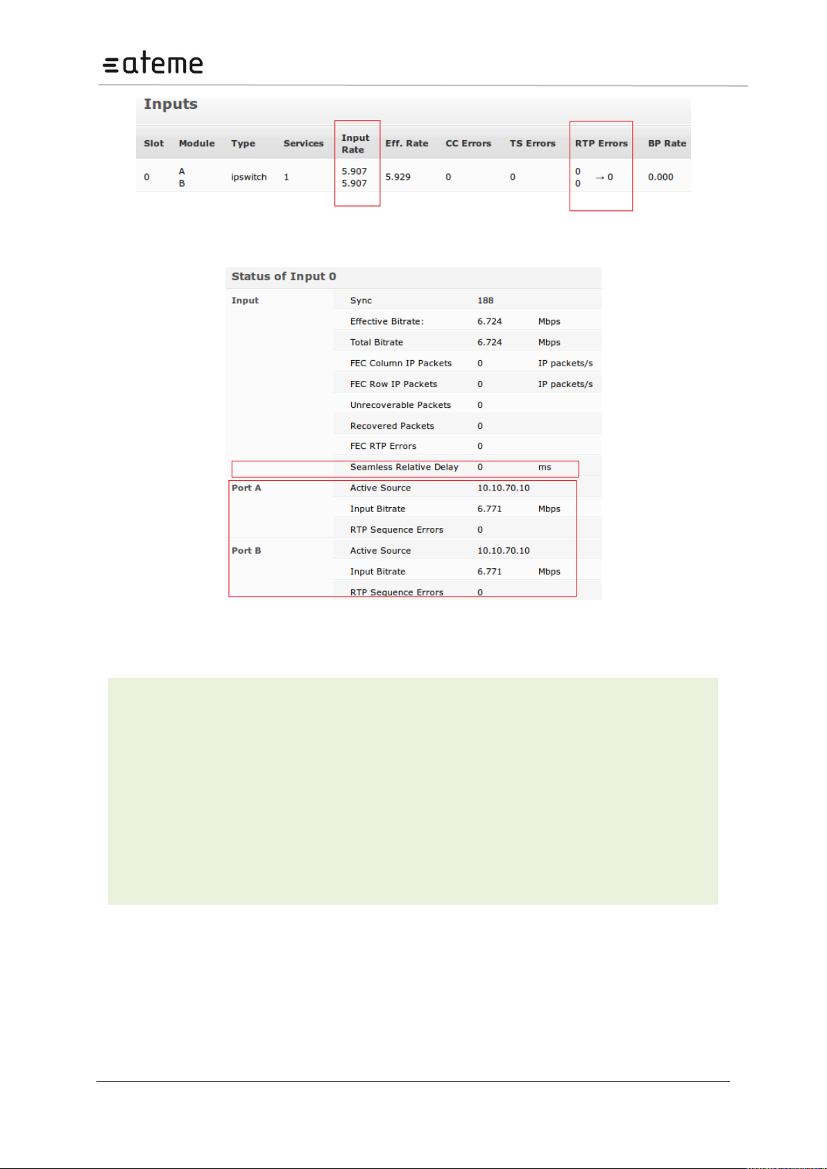
MC3x00 – User Manual
Seamless Relative delay
Seamless relative delay in ms will be displayed.
Port A Active source
Source A IP address
Port A Input Bitrate
Source A Input Bitrate in Mbps.
Port A RTP Sequence
Errors
Source A Real-time Transport Protocol sequence errors since last
Port B Active source
Source B IP address
Port B Input Bitrate
Source B Input Bitrate in Mbps.
Port B RTP Sequence
Errors
Source B Real-time Transport Protocol sequence errors since last
Figure 68 – IP Input Seamless module Status Parameter view
Figure 69 – IP Input Seamless module Status Parameter detailed view.
Additional status parameters for IP Input seamless module:
Page 68 / 213
Page 69
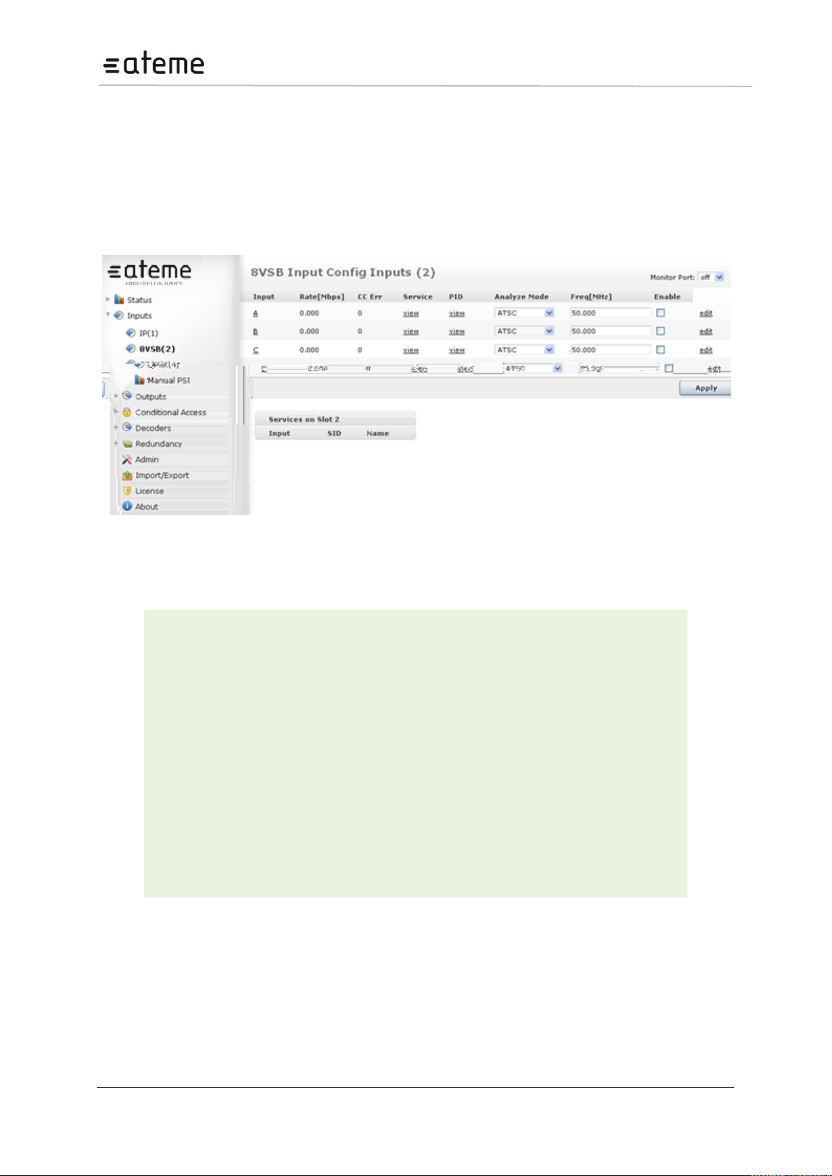
MC3x00 – User Manual
Input
Port on the 8VSB input module
Rate [Mbps]
Incoming data rate
CC Err
Continuity Counter Error – indicates that one or more packets are lost
Mode
Select one of the following modes:
DVB
ATSC
MPEG
No PSI analysis
The default mode is ATSC. If the incoming transport stream is not ATSC
compliant, use MPEG mode instead.
Freq[MHz]
Specify the currently tuned frequency in MHz, valid range is 47 – 861MHz.
Enable
Enable the corresponding input port
5.9 8VSB Input
The 8VSB input module can receive up to four individual 8VSB input streams. To configure the
module:
Switch to the Inputs node in the Navigation Pane
Select the 8VSB module you want to configure to display the module configuration (see Figure ).
Services available on all four 8VSB input ports will be listed in this view.
Figure 70 – 8VSB Input
The 8VSB input window shows all configurable settings as well as the current bitrate and service
information. The following parameters are available:
To monitor any of the demodulated 8VSB input signals, one of the 8VSB input ports can be assigned
to the output ASI monitor interface. The demodulated 8VSB input signal will then be copied onto the
monitor port for further analyzing or monitoring of the transport stream. Normal operation will not be
affected if the monitoring port is used.
The status parameters for the 8VSB module are shown in below. Click on the letter representing in the
input channel (A, B, C or D) to display the status parameters for the specific input port.
Page 69 / 213
Page 70

MC3x00 – User Manual
Sync
MPEG sync number: 188 or 204
Effective Bitrate
Effective bitrate of the input stream
Total Bitrate
Total bitrate of the input stream
Lock Status
Lock status of the tuner
Level
RF level measured in dBmV
MER
Modulation Error Radio in dB - a typical good reading is between 30 and
40 (the higher the better).
Figure 71 – 8VSB Status View
The following information is displayed:
Page 70 / 213
Page 71
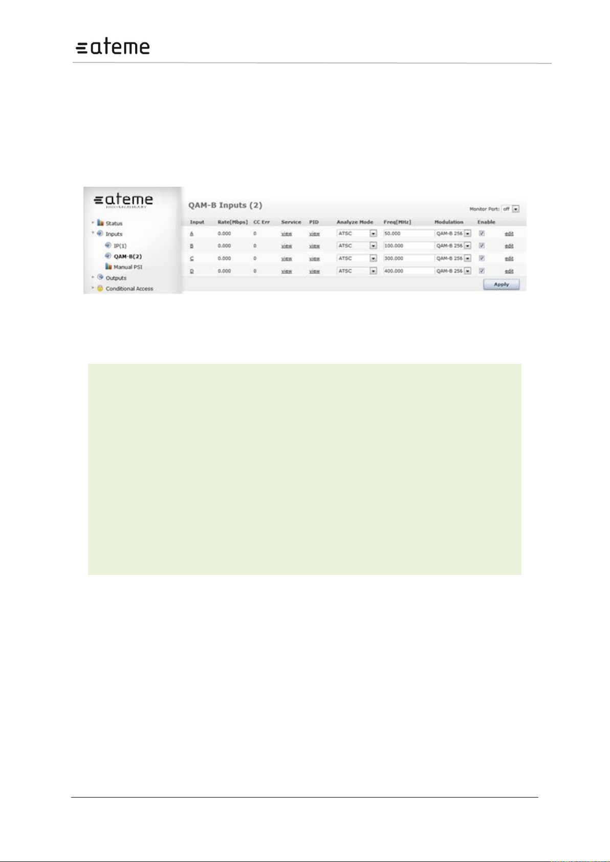
MC3x00 – User Manual
Input
Port on the QAM-B input module
Rate [Mbps]
Incoming data rate
CC Err
Continuity Counter Error – indicates that one or more packets are lost
Mode
Select one of the following modes:
DVB
ATSC
MPEG
No PSI analysis
The default mode is ATSC. If the incoming transport stream is not ATSC
compliant, use MPEG mode instead.
Freq[MHz]
Specify the currently tuned frequency in MHz, valid range is 47 – 861MHz.
Enable
Enable the corresponding input port
5.10 QAM-B Input
The QAM-B input module can receive up to four individual QAM-B input streams. To configure the
module:
Switch to the Inputs node in the Navigation Pane
Select the QAM-B module you want to configure to display the module configuration .Services
available on all four QAM-B input ports will be listed in this view.
Figure 72 – QAM-B Input
The QAM-B input window shows all configurable settings as well as the current bitrate and service
information. The following parameters are available:
To monitor any of the demodulated QAM-B input signals, one of the QAM-B input ports can be
assigned to the output ASI monitor interface. The demodulated QAM-B input signal will then be copied
onto the monitor port for further analyzing or monitoring of the transport stream. Normal operation will
not be affected if the monitoring port is used.
Page 71 / 213
Page 72
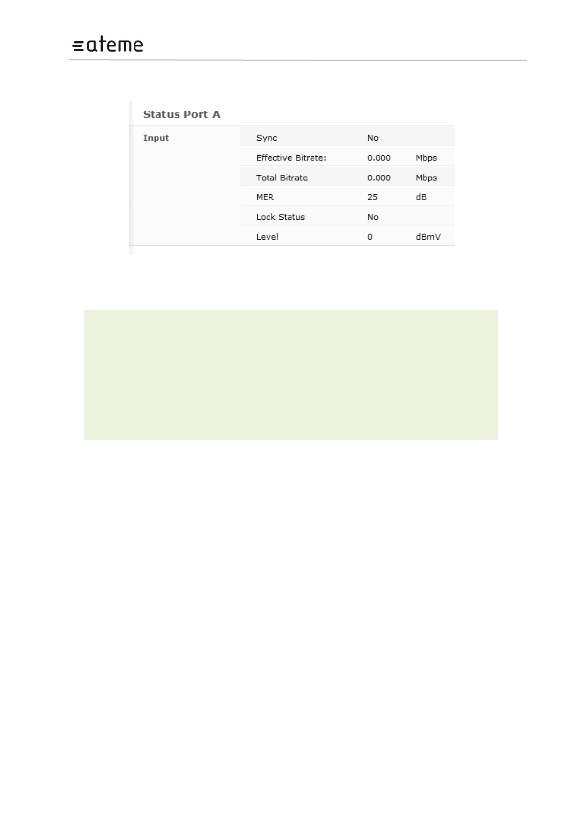
MC3x00 – User Manual
Sync
MPEG sync number: 188 or 204
Effective Bitrate
Effective bitrate of the input stream
Total Bitrate
Total bitrate of the input stream
Lock Status
Lock status of the tuner
Level
RF level measured in dBmV
MER
Modulation Error Radio in dB - a typical good reading is between 30 and 40
(the higher the better).
The status parameters for the QAM-B module are shown in below. Click on the letter representing in
the input channel (A, B, C or D) to display the status parameters for the specific input port.
Figure 73 – QAM-B Status View
The following information is displayed:
Page 72 / 213
Page 73
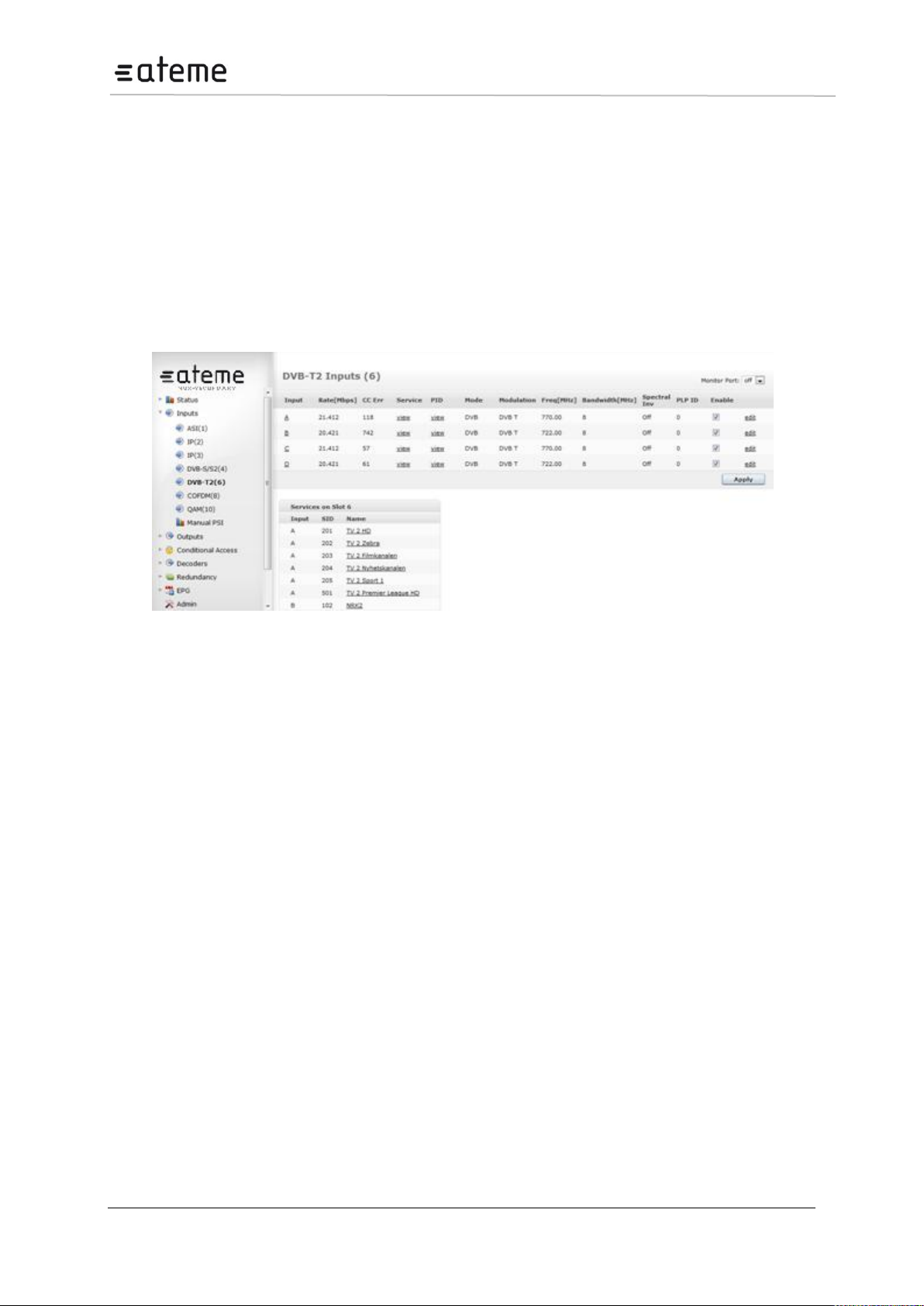
MC3x00 – User Manual
5.11 DVB-T2 Input
The DVB-T2 input module can receive up to four individual Frequencies. It comes in two different HW
configurations. One version has a single input connector that is distributed to the 4 demodulators
internally while the second version has 4 input connectors; one for each tuner. To configure the
module:
Switch to the Inputs node in the Navigation Pane
Select the DVB-T2 module you want to configure to display the module configuration (see Figure
below). Services available on all four DVB-T2 input ports will be listed in this view for each port type.
Supports PLP input selection. Note that in multi PLP environment it can only tune one PLP at a time.
Figure 74 – DVB-T2 Input
Page 73 / 213
Page 74
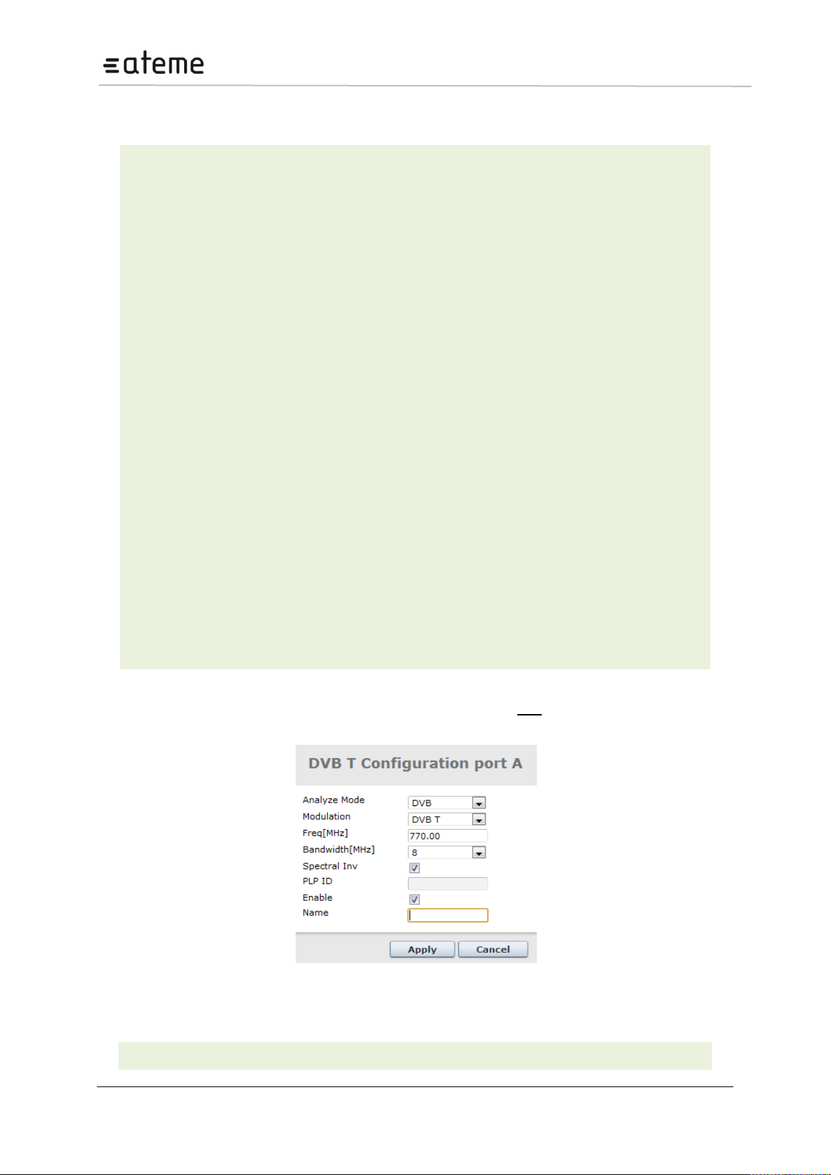
MC3x00 – User Manual
Input
Port on the DVB-T2 input module
Rate [Mbps]
Incoming data rate
CC Error
Number of Continuity Counter (CC) errors detected on all input ports since last
reset.
CC errors indicate that one or more packets are lost.
Service
Number of services present in the transport stream
PID
Listing all input PIDs for each input.
Mode
The mode of the input stream , either:
DVB
MPEG
ATSC
DVB (SDT)
OFF
Modulation
Select any of the following modes.
DVB-T
DVB-T2
Frequency
Specify the DVB-T/T2 frequency in MHz, valid range is 42 – 870Mhz.
Bandwidth [MHz]
Specify the bandwidth, select from 6, 7, or 8MHz
Spectral Inv.
Checking this check box activates the spectral Inversion.
PLP ID
Specify the PLP from the input.
Enable
Enable the corresponding input port.
Name
This parameter allows for each port in a module to be labeled. This label is visible as
The DVB-T/T2 node shows all major configuration settings as well as the current bitrate and service
information. The following parameters are available:
The above list of parameters can be configured by clicking on the edit link to the right of each input.
The pop up dialog below will be displayed:
Figure 75 – DVB-T/ Input Port Configuration
Page 74 / 213
Page 75
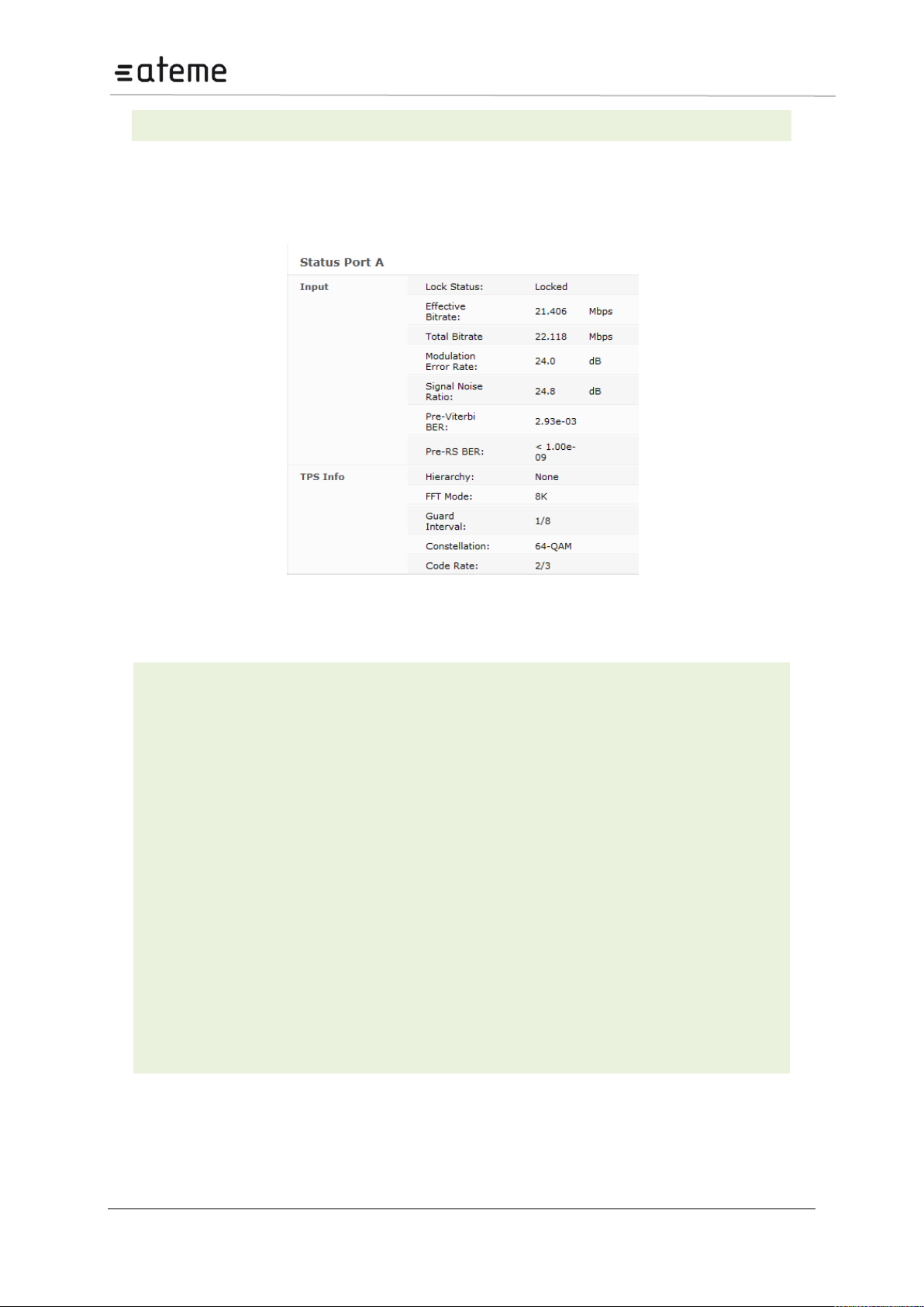
MC3x00 – User Manual
a tooltip when the mouse cursor hovers over the port.
Locked Status
Lock status of the tuner
Effective Bitrate
Effective bitrate of the input stream
Total Bitrate
Total bitrate of the input stream
Modulation Error
Rate
Modulation Error Radio in dB - a typical good reading is between 30 and 40 (the
higher the better).
Signal Noise Ratio
Signal to Noise Ratio – represents how much the signal has been corrupted by
noise.
Pre-Viterbi BER
Bit error rate before Viterbi error correction.
Pre-RS BER
Bit error rate after Viterbi / before Reed Solomon error correction
Hierarchy
Hierarchy of the currently tuned channel.
FFT Mode
Fast Fourier Transform Mode of the currently tuned channel.
Guard Interval
Guard Interval of the currently tuned channel.
Constellation
Constellation of the currently tuned channel.
Code rate
Code rate of the currently tuned channel
The status parameters for the DVB-T/T2 module are shown in the figure below. Click on the letter
representing the input channel (A, B, C or D) to display the status parameters for the specific input
port.
Figure 76 – DVB-T Status Parameter view
The following information is displayed in status parameters for DVB T/T2:
Page 75 / 213
Page 76
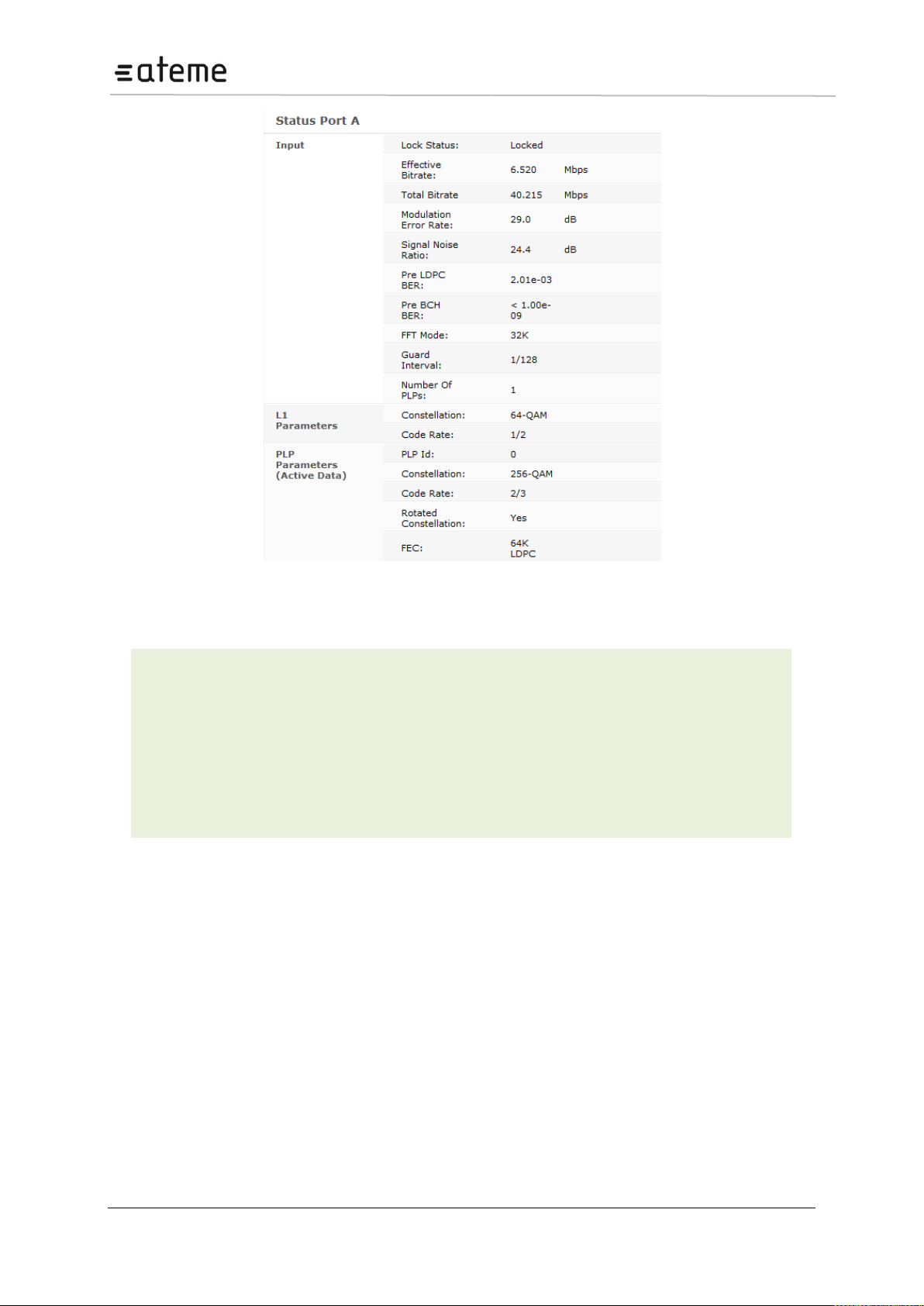
MC3x00 – User Manual
Pre LTPC BER
Bit error rate before LDPC error correction
Pre BCH BER
Bit error rate after LDPC / before BCH error correction, should <10-7.
Number of PLPs
Specify the count of PLPs
PLP Id
Specify the PLP Id
Rotated Constellation
Rotated Constellation of the currently tuned channel.
FEC
Forward Error Correction.
Figure 77 – DVB-T2 Status Parameter view
Additional status parameters for T2 demodulation:
Page 76 / 213
Page 77
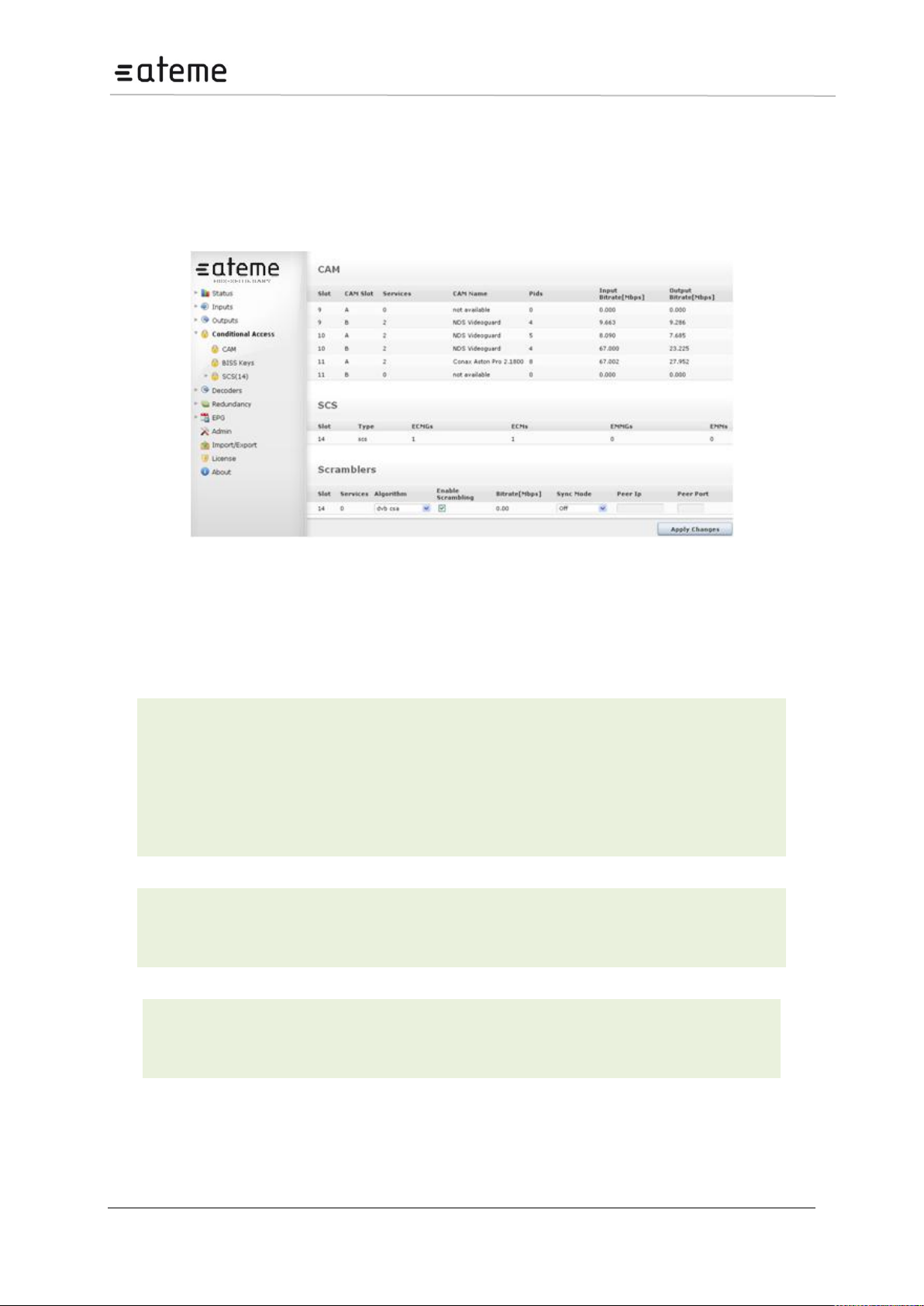
MC3x00 – User Manual
Services
Number of services being descrambled by the CAM
CAM Name
Name/provider of CAM module
PIDs
Number of PIDs currently being descrambled
Input Bitrate
Input bitrate into the CAM module
Output Bitrte
Output bitrate from the CAM module
Algorithm
Select the correct algorithm to be used for Scrambling based on the currently installed
licenses.
If you feel your chosen algorithm is missing, please contact ATEME support.
Algorithm
Select the correct algorithm to be used for bulk descrambling based on the currently
installed licenses.
If you feel your chosen algorithm is missing, please contact ATEME support.
6 Conditional Access Configuration
The unit supports descrambling and scrambling given that the required modules have been installed.
Descrambling and scrambling are processing elements; hence they are not listed in the Input or
Output nodes. These functions are found as part of the output service configuration, see Section
8.3.9.
Figure 78 – Conditional Access Node
The Conditional Access node displays existing configuration for CAMs, SCSs, Scramblers and
Descramblers.
The following parameters are available:
CAM:
Scramblers:
Descramblers:
6.1 Descrambling – Common Interface Module
The unit is capable of descrambling a number of incoming services with the installation of a
descrambler module. The descrambler module comes with two Common Interface slots and can
Page 77 / 213
Page 78
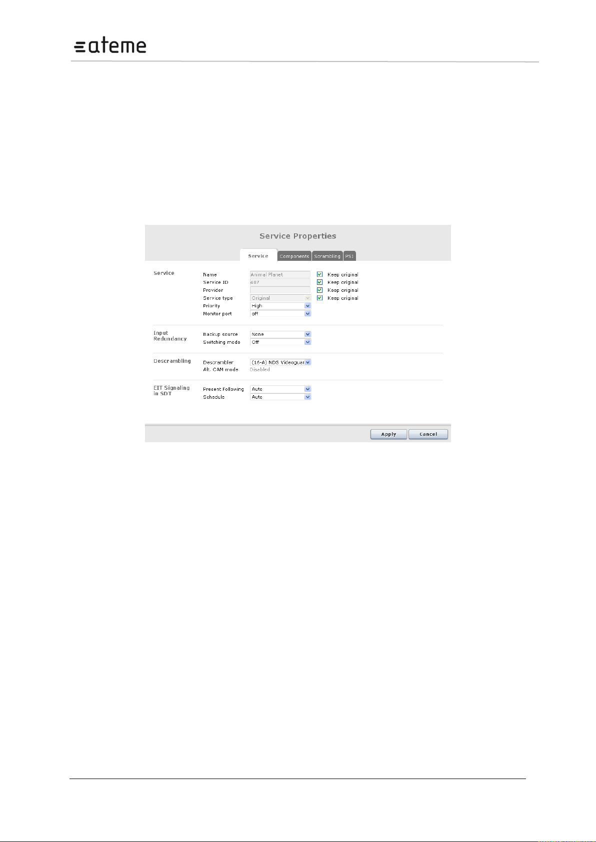
MC3x00 – User Manual
therefore host two Conditional Access Modules (CAM’s). Each Common Interface slot supports the
descrambling of one or more services depending on the CAM module used.
Refer to the decoder and radio module description section for details on how services can be
descrambled for these units.
6.1.1 Descrambling a Service
To descramble a service first insert the CAM into an available Common Interface slot, then insert your
Smart Card into the CAM.
To assign the Common Interface slot to a service to be descrambled, double click on that service and
within the Outputs page to display the Service Properties dialog (Figure 6.2).
Figure 79 – CAM Configuration within the Service Properties Dialog
6.1.2 Transporting a Descrambled Service to Multiple Output
Modules/Ports
A descrambled service may be sent to up to four individual outputs. In other words, if the unit is
configured with an IP output module and a QAM output module, then the descrambler module will be
able to copy the descrambled service and send it to both the IP output and QAM output destinations.
Alternatively, the same service can be sent to different ports on the same output module.
When an input service is configured to be sent to different outputs, the configuration is automatically
performed by the system – as long as the same descrambler is selected. This copy function is based
on per service, i.e. if a Smart Card is able to descramble up to 10 services, then the maximum number
of output streams from the descrambler will be 40 (10 x 4).
6.1.3 CAM Configuration
The CAM configuration page below (accessible by selecting Conditional Access CAM in the
Navigation Pane) displays the following:
A list of available CAM modules with its corresponding name,
The chassis slot where the Decoder or Descrambler module is installed, and
The CAM slot (each Decoder/Descrambler module has two CAM slots labeled A and B).
Page 78 / 213
Page 79
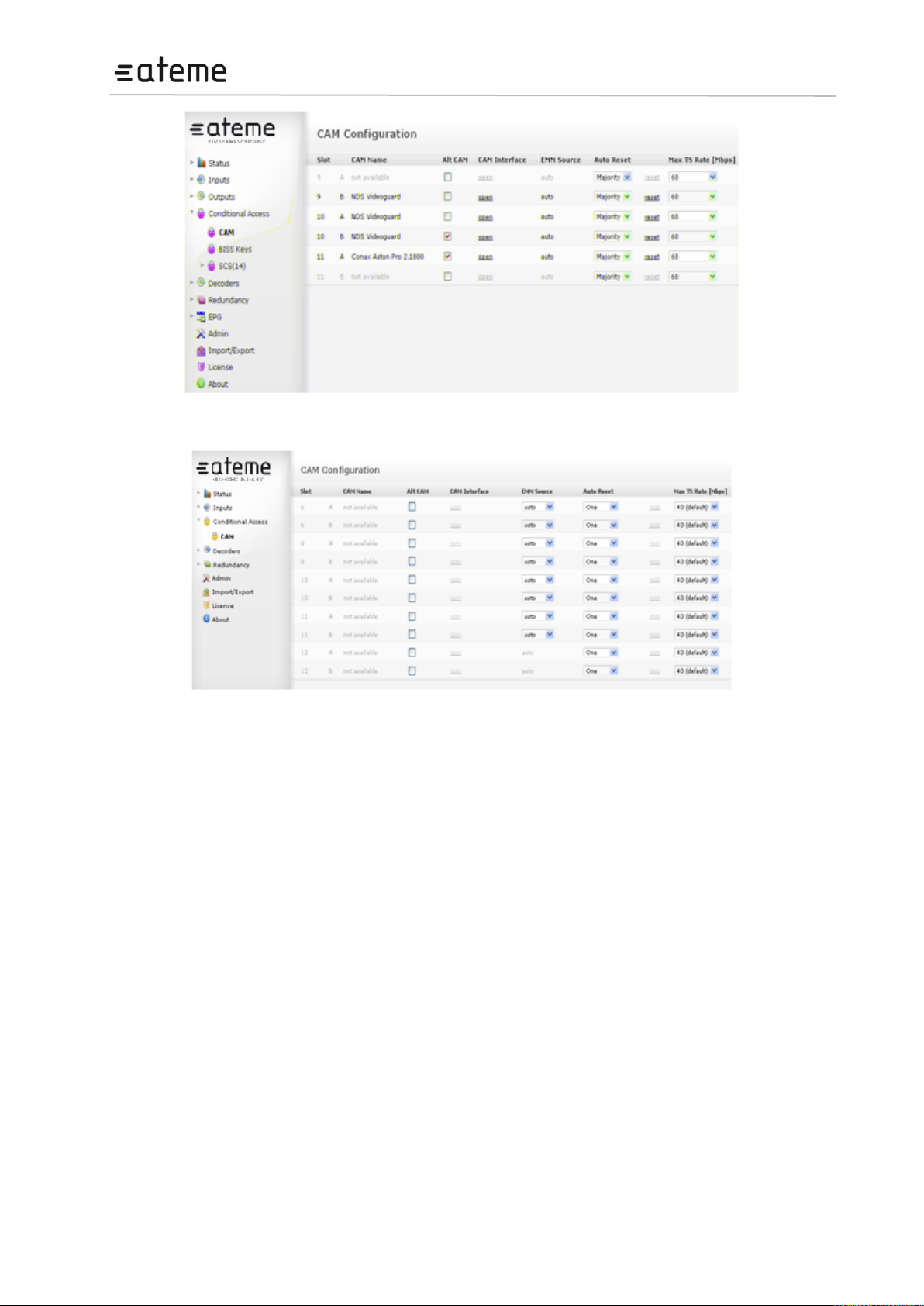
MC3x00 – User Manual
Figure 80 – CAM Configuration Page
Figure 81 – CAM Configuration Page (for chassis with a Quad Decoder)
If there is no CAM module in the Decoder/Descrambler module, CAM Name will be displayed as not
available.
Page 79 / 213
Page 80

MC3x00 – User Manual
Slot
Slot in which the Descrambler/Decoder is installed
CAM Slot
Slot in which the CAM module is installed – either slot A or B
CAM Name
Name of the CAM module
Alt CAM Mode
Activate sending of the entire input stream to the CAM without PID filtering explained in detail in Section 0.
CAM Interface
Displays the menu defined by the CAM manufacturer – explained in detail in
Section 6.1.5.
EMM Source
Displays the source of the EMM, the default value is auto. For the Quad
Decoder (3.3.8), depending on the number of decoder inputs, it is possible to
have more than one EMM source. In this case, a drop down box will be shown
- select the appropriate source.
Auto Reset
Automatic CAM Reset – enables the CAM to reset if there are failures in the
descrambling process. This helps the CAM to recover automatically without
requiring the user to reset manually. Auto Reset provides the following
options:
Off – automatic reset is disabled; the CAM can be reset manually.
One – if one or more services have descrambling failures, the CAM will reset.
Majority – if more than half the services configured to be descrambled in the
CAM fail, the CAM will reset.
All – in this mode, the CAM will simply reset if all services configured in the
CAM fail to be descrambled.
Man Reset
Manual CAM Reset – sometim
The Alt CAM Mode, CAM Interface, EMM Source, Auto Reset, Reset and Max TS Rate are the
configuration fields available in this page (Figure above).
Page 80 / 213
Page 81
MC3x00 – User Manual
It is generally advised to disable Alt CAM Mode as this creates a higher bandwidth
requirement in the unit.
We recommend you enable this option if you have problems with:
descrambling a service
keeping the subscription updated reliability
6.1.4 Alt CAM Mode
In a normal configuration, when an input stream is sent to the CAM, only a selection of PIDs that
comprise the services being descrambled are actually transmitted, together with CA- related PIDs
listed in the PSI.
In Alt CAM Mode, the entire input stream is sent to the CAM without PID filtering. This feature can be
useful in the following scenarios:
Some CA systems do not list all the required PIDs in the PSI. Often this will involve the EMM PIDs,
resulting in problems keeping the subscription updated over time. Alt CAM Mode can prevent this
problem.
Sending all the PIDs changes the packet timing of data streaming into the CAM to more closely
resemble that of the input. Testing has shown that very few CAMs require this to work reliably over time.
Not filtering PIDs sent to the CAM simplifies the input card configuration due to all input PIDs being sent.
This may slightly improve response time on service changes. The effect may be marginal, but it could be
of value, especially for inputs where most of the services are descrambled in the same CAM anyway.
The drawback of Alt CAM Mode is increased bandwidth usage from the input card(s) into the system.
In most systems, this is not a significant limitation; however, it should be taken into consideration for
large systems.
6.1.5 CAM Interface
Each CAM Module has its own menu structure defined by its manufacturer to access module
information, e.g. subscription status and to insert configuration data, e.g. a new PIN Code, maturity
rate and a key to descramble a service.
The CAM Interface feature allows operators to access and interact with these menus easily via the
web GUI. By clicking on Open under the CAM Interface column, a pop-up box appears over the CAM
Configuration page. This is the CAM Interface dialog.
6.1.6 Navigation
Based on Figure 82, the standard CAM Interface provides two buttons at the bottom and a list of
clickable menu options.
The Back/Exit button returns to the previous menu
If the Back/Exit button is pressed on a top-level menu, the same menu screen will be displayed
The Close button stops interaction with the CAM Module, closes the CAM Interface dialog, and
displays the CAM Configuration page
Page 81 / 213
Page 82
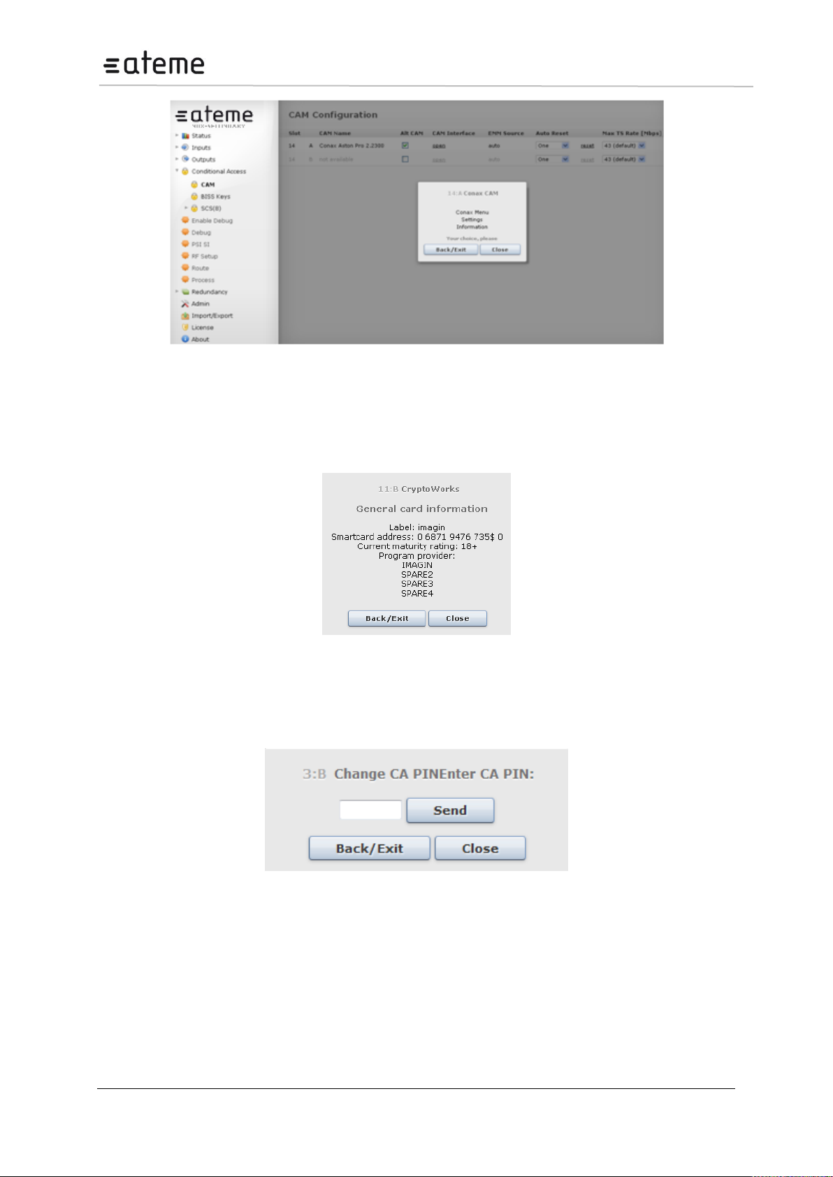
MC3x00 – User Manual
Figure 82 – Example of a Menu from Conax
It is possible that the dialog above varies depending on the CAM manufacturer. Menus
that do not allow user interaction are called Lists. Since Lists are bottom-level menu
items, possible operations are either to go back to the previous menu or close the CAM
Interface (Figure 6.5).
Figure 83 – Example of List from CryptoWorks
Another type of dialog is the Enquiry dialog (Figure 6.6). This dialog is displayed when the CAM
Module requires user input such as a PIN code. The CAM defines the maximum length of the input
data and whether actual characters are displayed as the user types.
Figure 84 – Example of Enquiry
6.1.7 Multiple Users and CAM access
The CAM Interface supports multiple users but not multiple sessions. This means that it is possible to
access the CAM Interface of the same CAM Module from different computers or browsers
simultaneously, but users cannot be on different levels of the menu. For this reason the CAM Interface
is refreshed every 10 seconds to request the current valid menu screen.
Page 82 / 213
Page 83
MC3x00 – User Manual
Error Message
Description
Error: No session.
Refresh to recover
communication
The user is trying to answer a menu or enquiry and the session has
been closed.
Error: Session ID.
Refresh to recover
communication.
The user is trying to access a session that is no longer available.
Error: Status. Refresh to
recover communication.
The status count value received from GUI is not the same as the one in
the CAM Interface. This means that the GUI could be in another level of
the menu which can lead to a non desired operation.
Error: Invalid message
format.
The message parsing process is not successful.
Error: CAM No
response. Refresh to
recover communication.
Within a specified timeout, the CAM Interface failed to respond.
No CAM/PC Card in
slot.
There is no CAM Card in the slot.
CAM not identified, or
identified as non-CAM.
The PC Card is not identified, or identified as non-CAM.
Due to this synchronization scheme the menu screen will change for all current users even if just one
of them interacts with the CAM Interface dialog.
Multiple users interacting with a single CAM Module can lead to synchronization errors. For instance,
when one user tries to access a menu that has not been refreshed after another user has interacted
with it, a synchronization error will occur. This will display a Status error. This and other errors are
handled by the CAM Interface to provide safe and consistent interaction.
6.1.8 Error Handling
When a situation results in an error and does not permit proper communication with the CAM Module,
an error message will be displayed. There are different conditions that can lead to errors. Table 2 lists
the possible error messages and their descriptions.
Table 2 - Error Messages and their Descriptions
When an error message is displayed, the Back/Exit button is replaced by Refresh. The operator can
either close the CAM Interface, or try to Refresh the session. If a synchronization error occurs,
Refresh is the ideal solution. Otherwise, the operator can wait for the CAM Interface to request a
Refresh automatically.
Page 83 / 213
Page 84
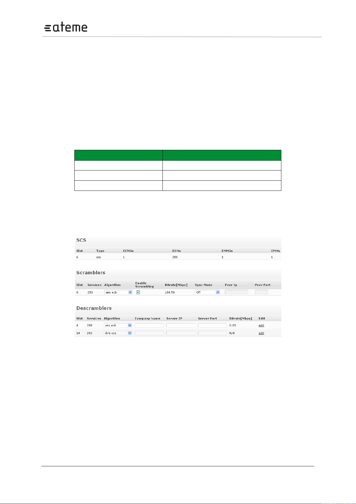
MC3x00 – User Manual
CA System
Number of Services Supported
BISS
250 services
Latens
250 services
Verimatrix
250 services
6.2 Bulk Descrambling
MC3x00’s bulk descrambler is able to descramble up to 250 services per card. Actual descrambling is
performed in firmware while extraction of the Control Word from the ECMs is done by integrated soft
clients provided by the CA vendors. The bulk descrambler runs on a dedicated module, providing an
external Ethernet port used for the communication between the soft client and the CA server for
exchange of access criteria.
The maximum number of ECMs that can be descrambled depends on the processing power
requirement of the CA client.
Currently the descrambler algorithms supported are: DVB-CSA or AES-ECB; but not both
simultaneously.
Below are the CA systems integrated with the bulk descrambler module:
Preparing the bulk descrambler module to descramble services requires some initial configuration to
establish a link to the CA vendor’s server. To be able to view the GUI and enter necessary
parameters, the correct licenses must be installed as the bulk descrambler functionality is licensed
together with the number of services.
Figure 85 – Setting up the Bulk Descrambler Module
Page 84 / 213
Page 85
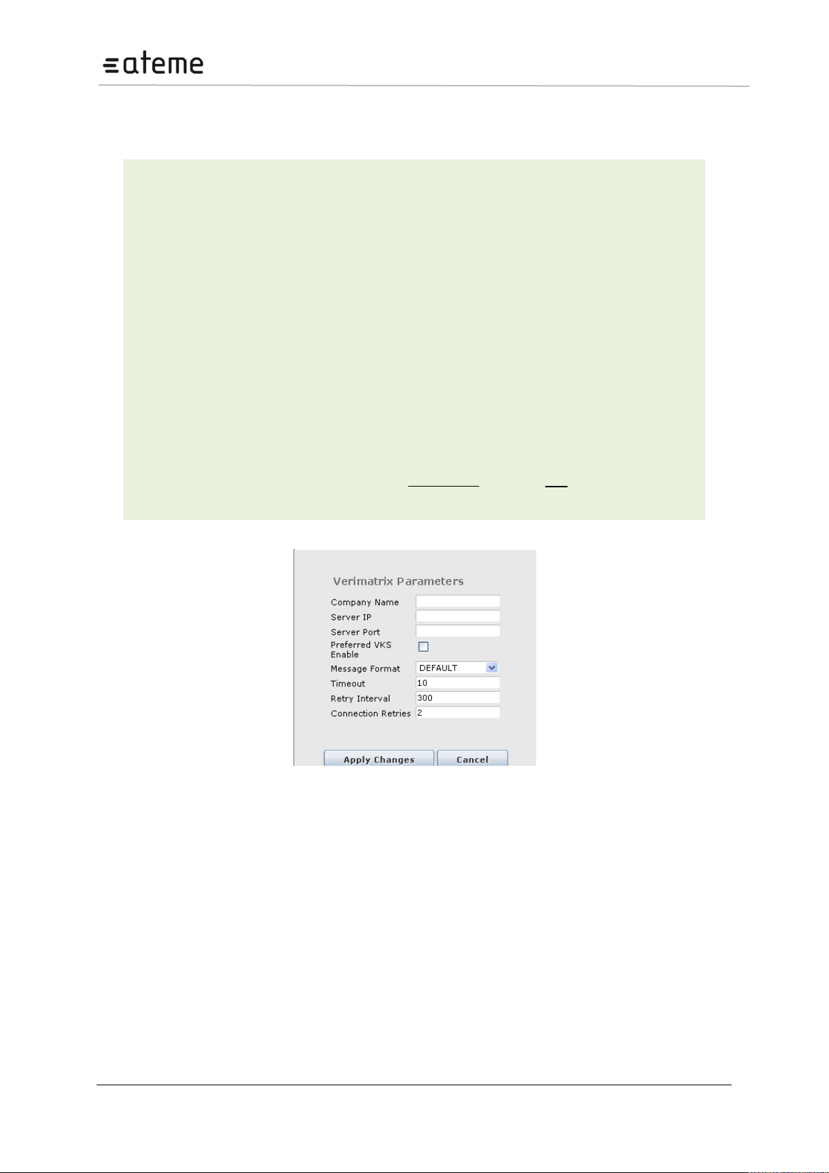
MC3x00 – User Manual
Slot
Slot in which the descrambler module is installed
Services
Number of services currently active
Algorithm
Descrambling is performed in FPGA. Depending on the FPGA installed, different
algorithms will be available. Select an algorithm after installing a descrambler.
Company Name
A unique key that will be exchanged with the CA system (provided by your CA
vendor)
Server IP
IP address of the CA vendor’s server
Server Port
CA vendor port to be used
Bitrate [Mbps]
Total bitrate passing through the descrambler
Edit
This is a Verimatrix specific parameter.
It is possible to configure the verimatrix.ini file via the edit link. The dialog shown
in Figure below will be displayed.
6.2.1 Verimatrix Configuration
The following parameters are available:
Figure 86 – Configuring Verimatrix Parameters
Page 85 / 213
Page 86
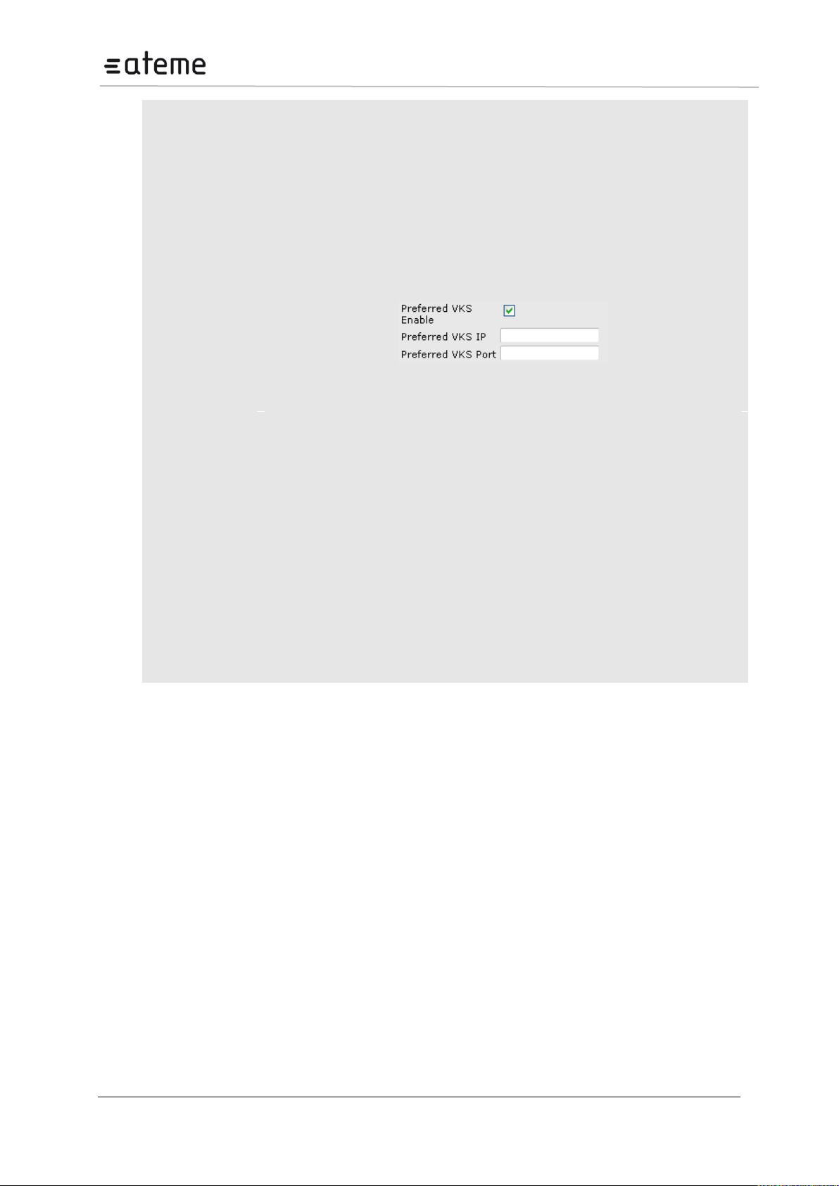
MC3x00 – User Manual
Company Name
A unique key that will be exchanged with the CA system (provided by your CA
vendor)
Server IP
IP address for the CAS server
Server Port
IP port for the CAS server
Preferred VKS
Enable
Enables connection to an external Verimatrix Key Server (VKS). Checking this
checkbox displays the following additional parameters ( Figure below):
Preferred VKS IP – IP address for the external key server
Preferred VJS Port – IP port for the external key server
Figure 87 – Additional VKS Parameters
Message
Format
The communication format for messages sent to the CAS server. Choose one of the
following:
DEFAULT
1153
1154
1155
1156
1157
Timeout
Duration of timeout for connecting to the CAS server.
Retry Interval
If the previous attempt to connect to the CAS server failed, the retry interval is the
time it takes before the client attempts to connect again.
Connection
Retries
Number of times the client will attempt to connect to the CAS server before giving
up.
Once the bulk descrambler has been initialized, outgoing services can be descrambled in the same
manner as the standard CAM based solutions – by selecting the descrambler module to be used for
descrambling in the Service Properties dialog (on the output configuration page). A similar procedure
is necessary for Radio and decoder modules too.
Page 86 / 213
Page 87
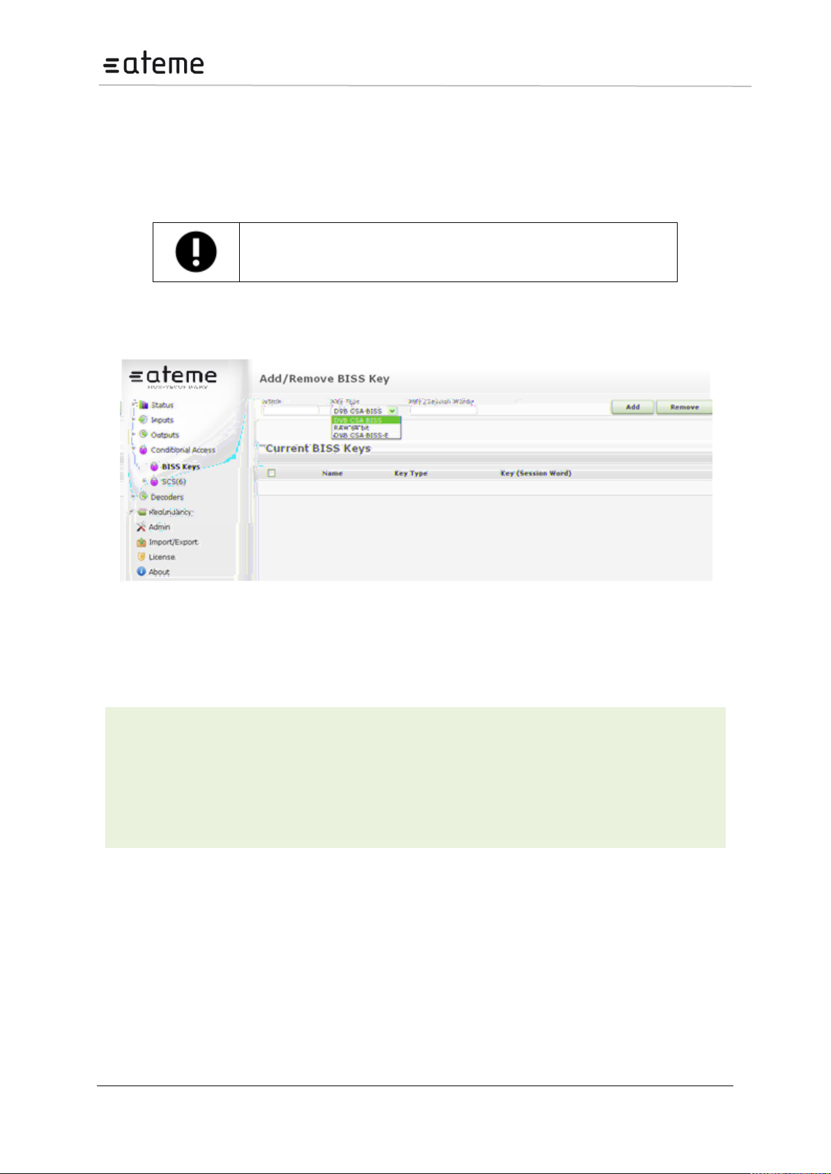
MC3x00 – User Manual
BISS descrambling can also be done via a CAM based system where the
key is inserted using the CAM interface. Detailed explanation on BISS
descrambling with CAM systems is beyond the scope of this manual.
Name
Name for the key
Key Type
Select one of the following:
DVB CSA BISS (12 bytes)
RAW 64 Bit
DVB CSA BISS-E (16 bytes)
Key (Session Word)
Control word used for scrambling or descrambling
6.2.2 BISS Scrambling and Descrambling
6.2.2.1 Key Handling
The unit supports BISS scrambling and descrambling (Mode 1 and Mode E), which is the simplest
form of fixed key scrambling available. The scrambling solution is based on the standard scrambler
card, while the descrambling is based on the bulk descrambler card.
The key handling procedure is identical for both scrambling and descrambling. A key can be defined
and associated with a name, which is the reference used for the stream’s configuration.
Figure 88 – Creating a BISS Mode 1 Key
The figure above illustrates a GUI with one existing key named test. The “test” key may be used both
for descrambling and scrambling.
The following parameters are available:
In BISS Mode E the key (Session Word) is protected by encrypting it using a key ID. An encrypted key
is generated by selecting DCB CSA BISS-E as key type, and using the Encode mode, and supplying
the key ID and key. The resulting encrypted key is displayed to the user in a popup when the key is
added, but is not available to the user later in time. The same procedure is used in order to retrieve a
clear key from an encrypted key and key ID by selecting the Decode mode.
6.2.2.2 Setting up a BISS Scrambler
To configure an outgoing stream with the defined BISS key, check the Fixed Key checkbox in the
scrambler setup page.
Page 87 / 213
Page 88
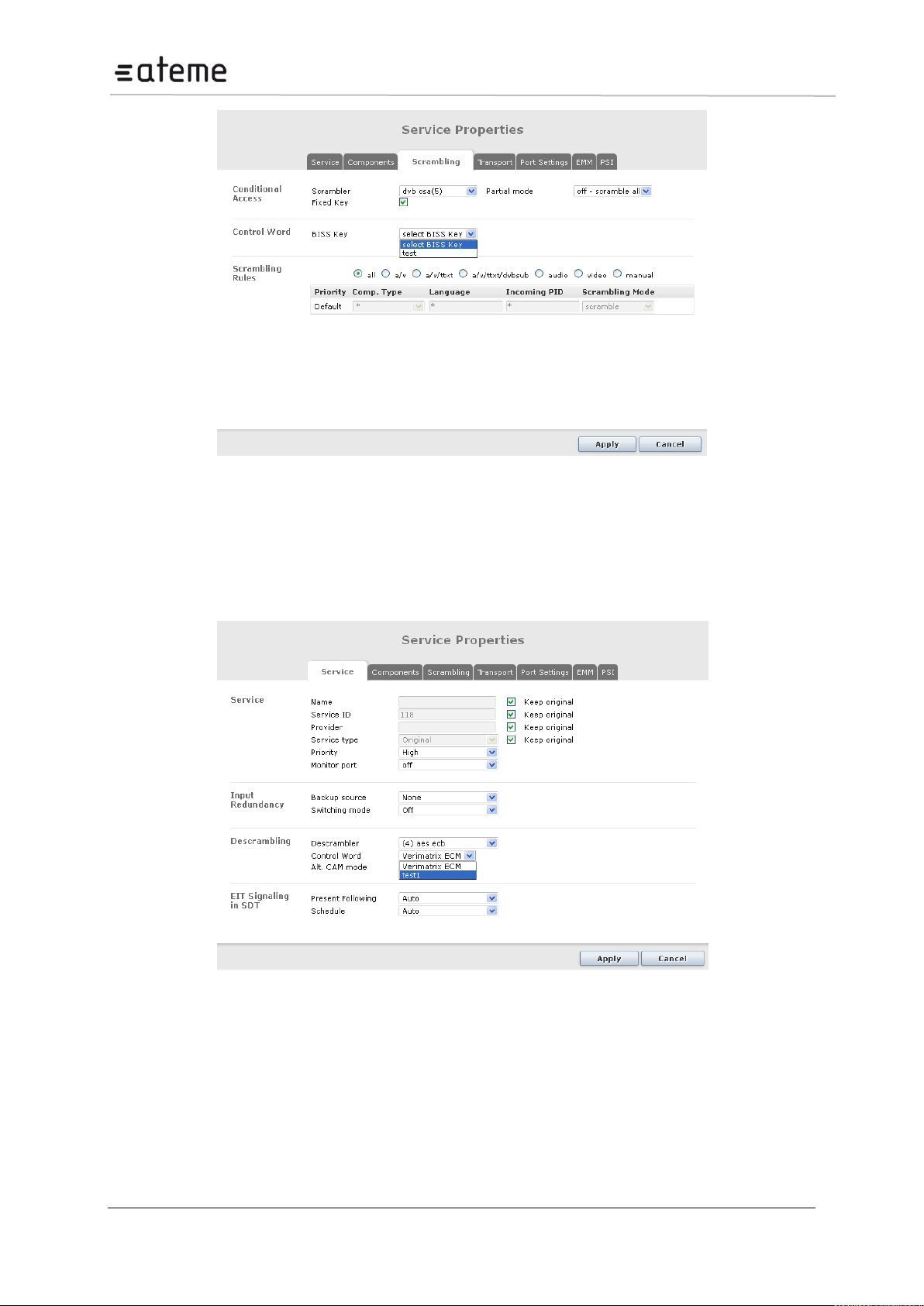
MC3x00 – User Manual
Figure 89 – Setting up a BISS Scrambling Service
The BISS Key dropdown box will list all previously defined keys.
6.2.2.3 Setting up a BISS Descrambler
To descramble an outgoing stream with the defined BISS key, select the appropriate descrambler card
and key to be used in the output service configuration page.
Figure 90 – Setting up a BISS Descrambling Service
Page 88 / 213
Page 89
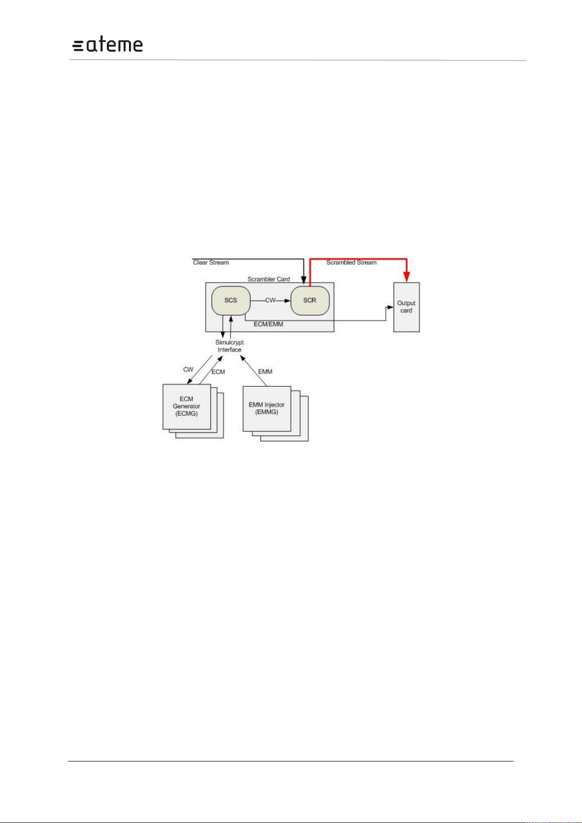
MC3x00 – User Manual
6.3 Scrambling
This section provides a brief overview on how scrambling is performed within the unit. It introduces the
different components required and their purpose and explains how to setup the scrambler card to
establish ECM and EMM channels as well as their actual streams.
For information on how to conduct scrambling, add an EMM to an output transport stream, etc. refer to
Chapter 0.
The scrambler module is composed of two components:
SCS – a software component responsible for managing the interfaces used by external ECMG, EMMI,
and EIS services.
SCR – a hardware component responsible for encryption (DVB-CSA or AES) of the services.
The functional diagram below shows these components and their relations with the rest of the system.
Figure 91 – Scrambler Module Architecture
The SCS module is the master of the scrambling system. It is aware of the ECMG and the scrambler
module. Upon configuration, the SCS card generates a CW, sends it to the ECMG, which returns the
ECM. The SCS then sends the CW to the hardware component scrambling the live content and
transfers the ECM to the correct output card for playout.
Before it is possible to define an output stream with the scrambling properties it is necessary to define
the ECM generator, as the SCS needs to know where to contact the encryption system. Next step is to
define an ECM. The ECM definition associates a CW id and access criteria. The output can now be
defined and scrambled. When configuring the output to be scrambled the ECM selection list implicitly
represents the CW and access criteria while the scrambler indicates the scrambler card.
Page 89 / 213
Page 90
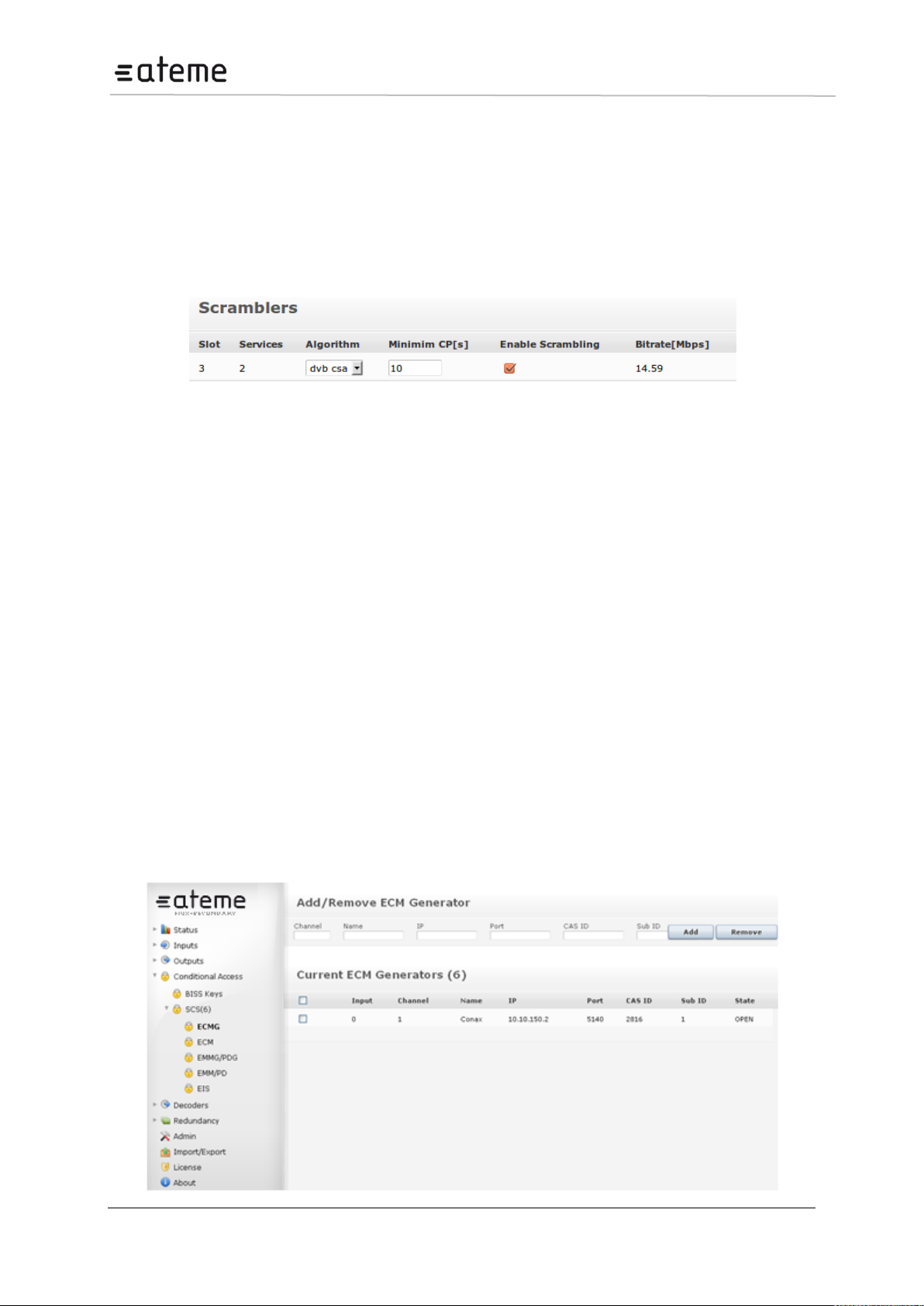
MC3x00 – User Manual
6.3.1 Scrambler Module Configuration
The scrambler module runs both the SCS functionality and the scrambler functionality on one single
card. The Scrambler supports both the DVB-CSA and AES scrambling algorithms – but only one at a
time.
The scrambler card supports up to 250 scrambled services, with a maximum total bitrate of 850Mbps.
An overview of the scramblers present in the unit is available in the Conditional Access node in the
Navigation Tree.
Figure 92 – Scramblers Overview
This configuration page gives a general overview of how many ECMs and EMMs have been
configured as well as providing a dialog to select which scrambling algorithm to run on the card
(available algorithms depend on the licenses and SW version installed). The options provided here are
based on the information reported by the scrambler card during startup.
6.3.1.1 Configurable crypto period on the scrambler
It is possible to configure a user definable minimum crypto period (CP) per scrambler card, under
Conditional Access > Scrambling (Figure 6.15). The minimum crypto period default is 10 seconds,
which is the minimum crypto period supported, but can be set as high as 6553 seconds.
If the nominal CP duration is changed as a consequence of a user changing the minimum CP, the
change takes effect the next CP. Thus, the current CP is not interrupted (neither shortened nor
lengthened in time).
6.3.1.2 Selective Scrambling/Partial Scrambling
The scrambler card supports both selective and partial scrambling, implying that parts of the content
are sent in clear. Selection is done per service and is enabled during the configuration of the output
stream. Selective scrambling is only available for selected CA systems and requires a license.
6.3.1.3 Configuring an ECM Generator Channel
A connection to an ECM generator is defined in the ECMG node located under the Conditional
Access SCS node in the Navigation Tree. The connection to an ECMG establishes a channel
over which ECMs will be sent.
Page 90 / 213
Page 91
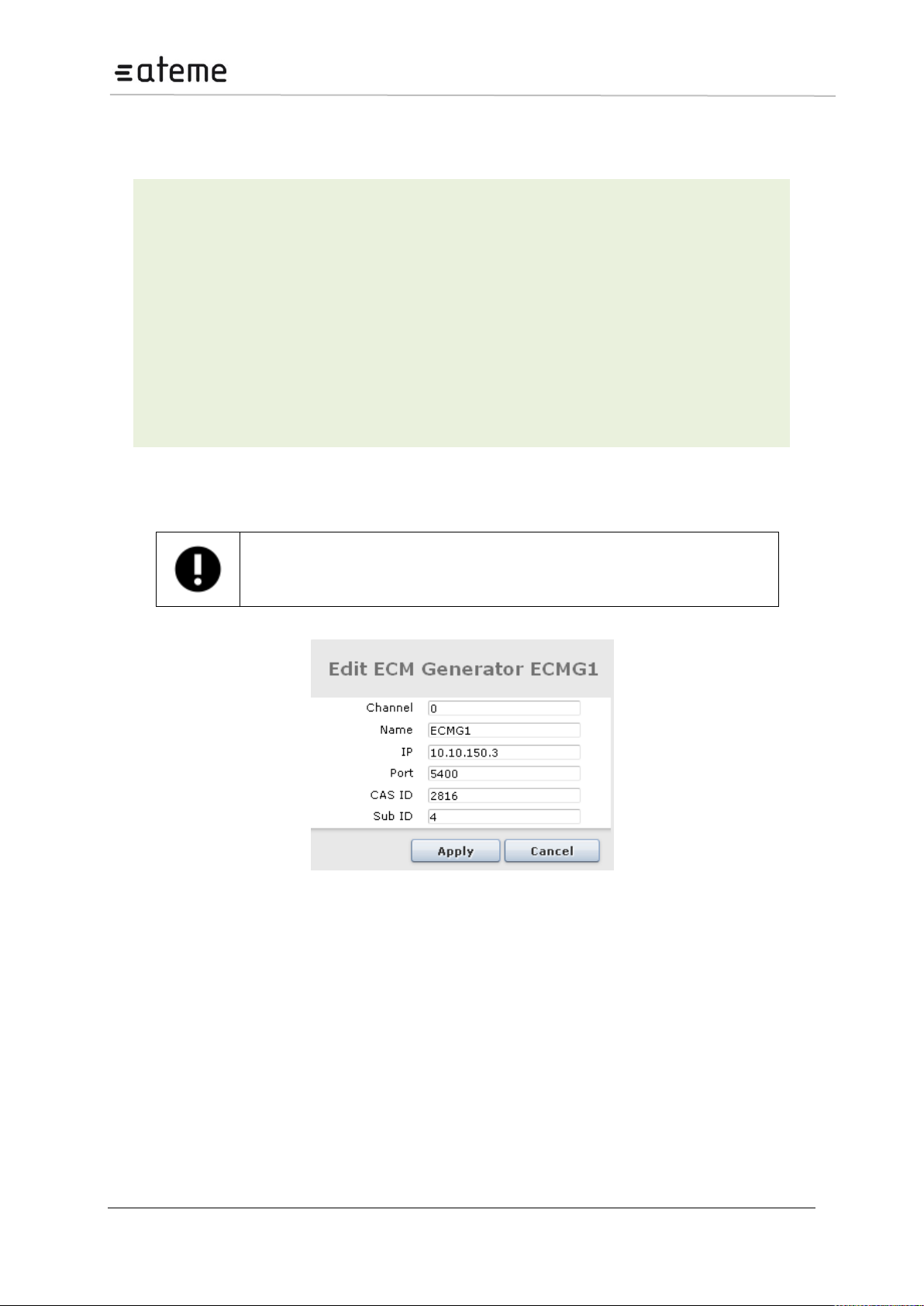
MC3x00 – User Manual
Input
Logical port representing the connection to the ECMG – assigned automatically. This
number is used internally as well as for generating alarms.
Channel
The SimulCrypt Channel ID used for the CA system
Name
For reference in the GUI only
IP
IP address of the ECMG
Port
TCP port of the ECMG
CAS ID
CA vendor specific ID
Sub ID
CA vendor specific sub ID
State
Status of ECMG connection, either OPEN or NOT CONNECTED.
It is possible to have several ECMG connections simultaneously but the CAS ID has
to be uniquely defined. If the same CAS ID is used, a real SimulCrypt will not work
as the CA Descriptor in the PMT will be identical for both ECMs. In this case, private
data must be used by STBs to distinguish ECMs.
Figure 93 – Adding an ECM Generator
The following information is displayed:
To change an, ECMG channel connection click on the existing ECMG entry and enter the new
configuration.
Figure 94 – Editing ECMGs
6.3.1.4 Configuring the CryptoLITE embedded ECM Generator
CryptoLITE is an embedded ECM Generator running on the scrambler card. To establish a channel
connection to CryptoLITE, use the following mandatory parameters:
IP: 127.0.0.1
Port: 5555
CAS ID: 19178
The ECMG will accept one channel only; up to 250 ECM streams are supported. When adding an
ECM, the Access Criteria field may be left empty. However, it is possible to enter a fixed 8-byte (16
HEX characters) user specified scrambling key in the Access Criteria field.
Page 91 / 213
Page 92
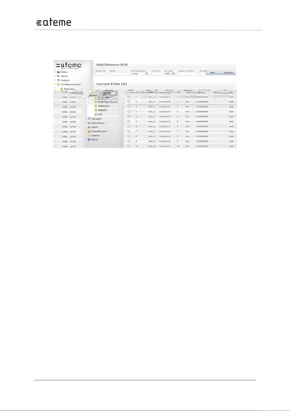
MC3x00 – User Manual
6.3.1.5 Configuring an ECM Stream
An ECM is defined from the ECM node in the Navigation Tree. The ECM entry links a CW and
Access criteria to an ECM Generator.
Figure 95 – Adding an ECM
Page 92 / 213
Page 93
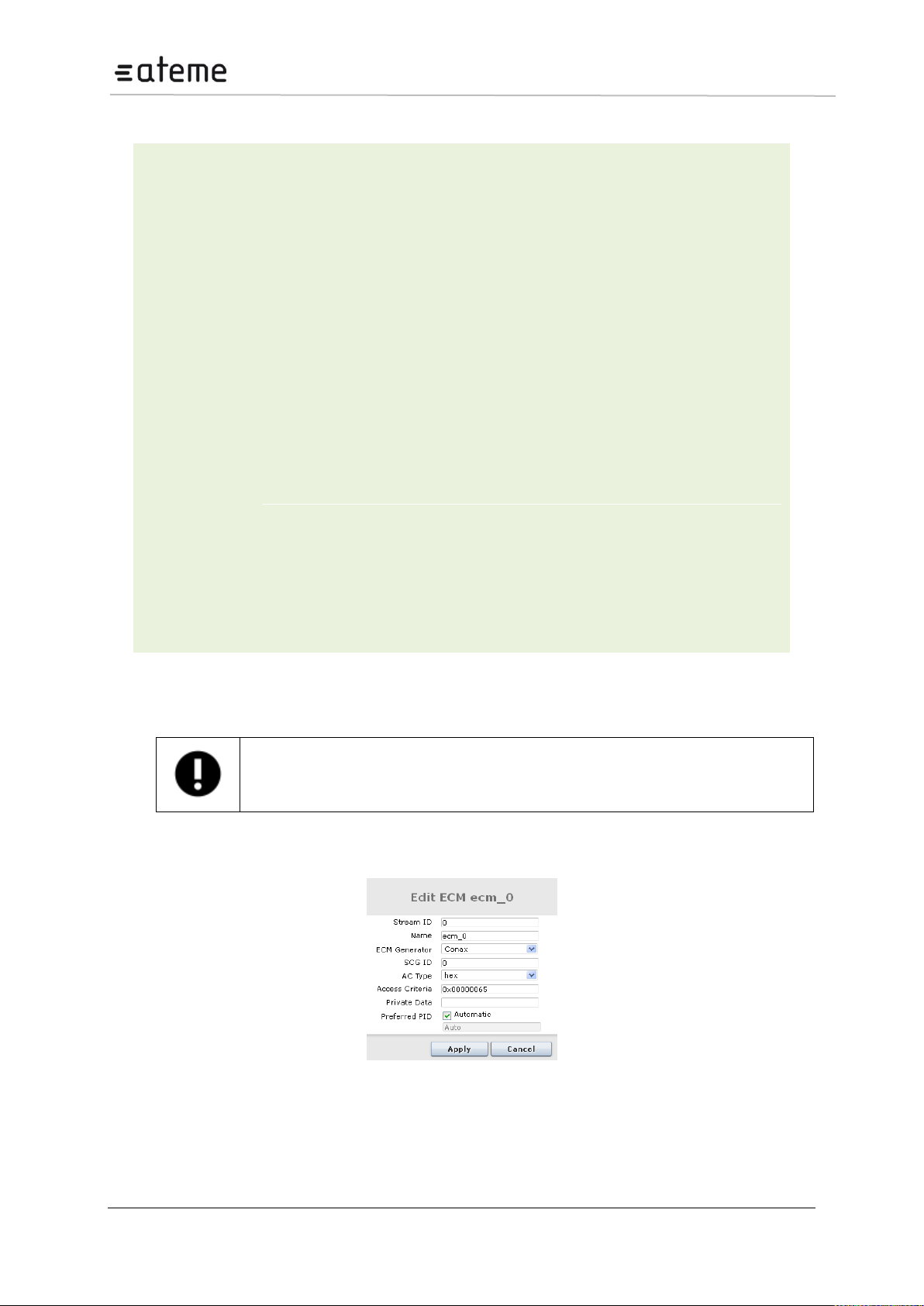
MC3x00 – User Manual
Stream ID
The SimulCrypt Stream ID used towards the CA system. Its value is also set to the
SimulCrypt EcmId.
Name
For reference in the GUI only
ECM Generator
Links the ECM to the predefined ECMG
SCG ID
CW selection; all ECMs with the same SCG id will share the same CW.
AC Type
Access Criteria type – refers to the data type used over the SimulCrypt protocol
when the access criteria are transferred. Available types are: UTF16, INT32, or
HEX.
Access Criteria
Specified in decimal or HEX (use 0x prefix)
Private Data
Private descriptor data added to the ca_descriptor in the PMT; enter in HEX using
the 0x prefix.
PID
Preferred ECM PID value transmitted at the output module; the maximum value is
8191.
State
OPEN or CLOSE
CP Number
This is a reference number for both CAS and scrambler. It represents the number of
exchanges between the ECMG and the scrambler; the value is controlled by the
ECMG.
At this point, the ECM stream is defined and the CA system as well as the SCS module
can begin to exchange CW and ECMs. However, the ECM is still not associated to any
output. Refer to the Output Configuration chapter for details on how to associate ECMs to
outputs.
The following information is displayed:
If multiple ECMG connections have been defined, the same SCG ID may be used for two ECMs as
long as they are connected to different ECMGs.
To change an, ECM configuration click on the existing ECM entry and enter the new configuration.
Figure 96 – Editing an existing ECM
Page 93 / 213
Page 94
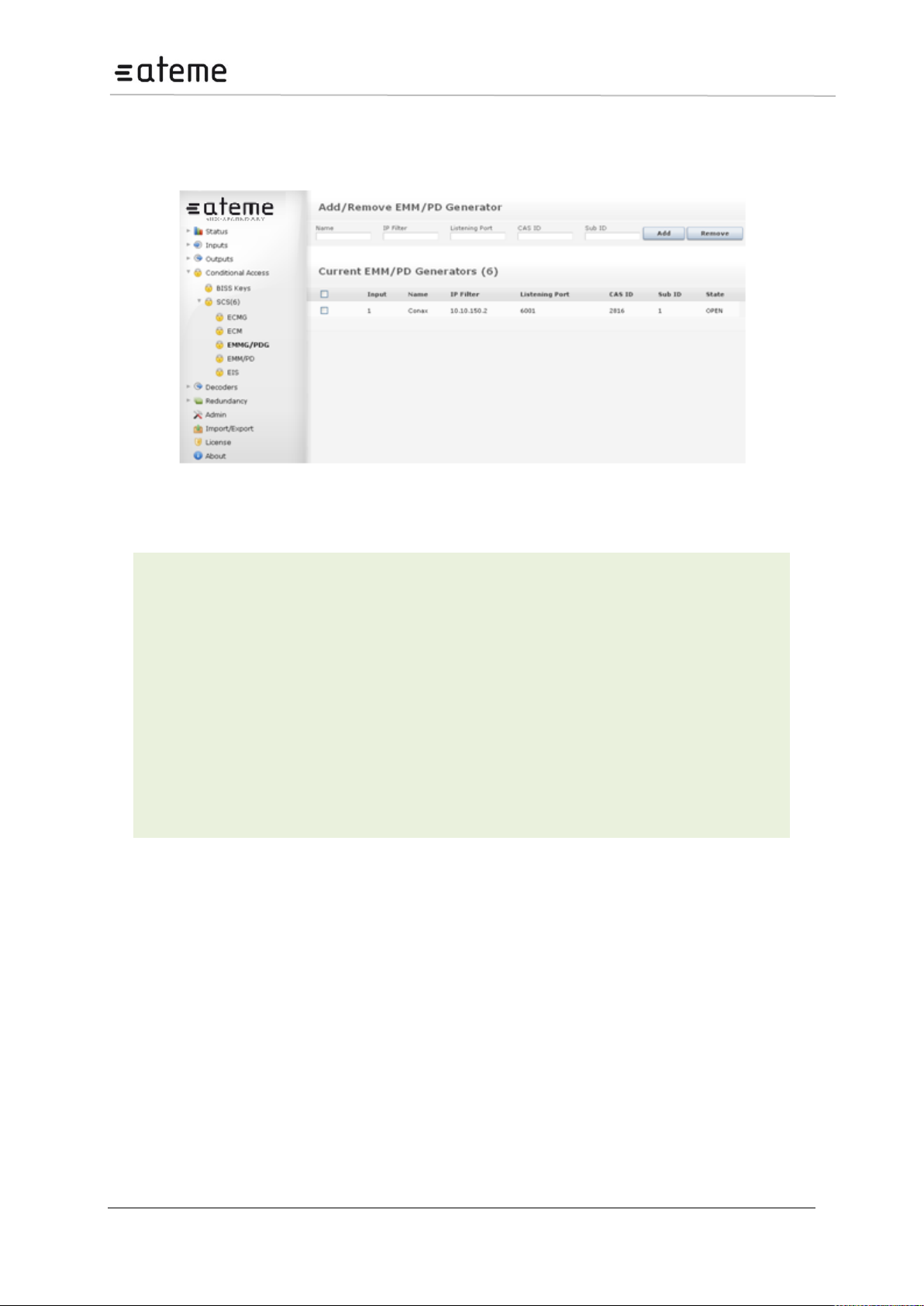
MC3x00 – User Manual
Input
Logical port representing the connection to the EMMG – assigned automatically. This
number is used internally as well as for generating alarms.
Name
For reference in the GUI only
IP Filter
IP address of the EMMG to be connected to. If the value 0.0.0.0 is used, the unit will
accept a connection from any IP address. When multiple sources are trying to connect,
it is first come first serve.
Listening
Port
TCP port for the EMMG to connect to
CAS ID
CA vendor specific ID
Sub ID
CA vendor specific sub ID
State
Status of the EMMG/PDG connection, either OPEN or NOT CONNECTED.
6.3.1.6 Configuring an EMM Generator (EMMG) Channel
To establish a connection to an EMM Generator (or Private Data Generator), go to Scrambler SCS
EMMG/PDG node in the Navigation Tree, enter appropriate values and click Add.
Figure 97 – Adding an EMM Generator
The following information is displayed:
Page 94 / 213
Page 95
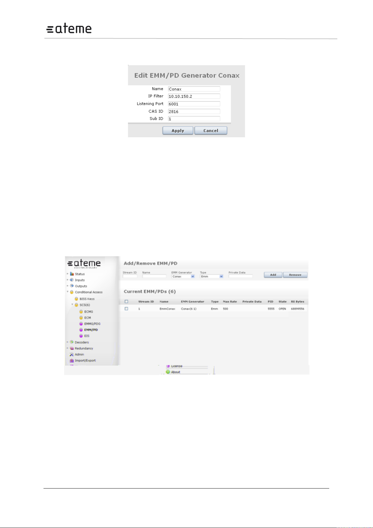
MC3x00 – User Manual
To change an, EMMG channel connection, click on the existing EMMG entry and enter the new
configuration.
Figure 98 – Editing an EMM Generator
EMM/PD Bandwidth
During the EMM/PD stream configuration the SCS and the EMM/PD generator will negotiate the
maximum bandwidth allowed for a given stream. This bandwidth has a default value of 100kbits/s and
can be also set explicitly from the GUI. The maximum total bandwidth available per card is 3
Mbits/s for these streams.
In the case where the CA system is transmitting more data than the SCS card can handle, the CA
system will indirectly be notified as the flow control mechanism in the TCP stack will notify the
transmitter; hence the CA system can take appropriate measures to avoid overflow.
6.3.1.7 Configuring an EMM/PD Stream
An EMM/PD is defined from the EMM/PD node in the Navigation Tree.
Figure 99 – Adding an EMM/PD
Page 95 / 213
Page 96
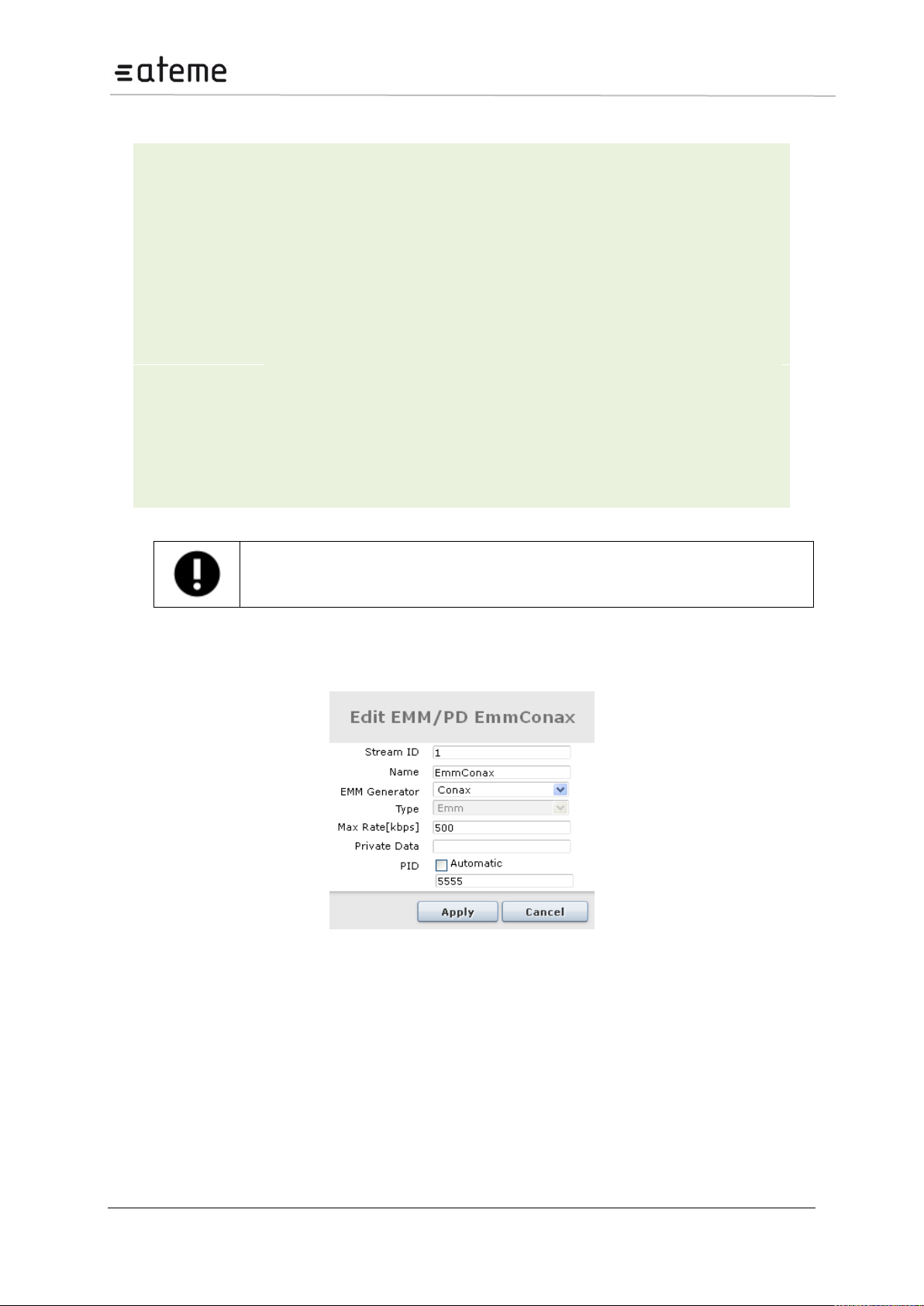
MC3x00 – User Manual
Stream ID
The SimulCrypt Stream ID used towards the CA system. Its value is also set to the
SimulCrypt DataId.
Name
For reference in the GUI only
EMM Generator
Links the EMM to the predefined EMMG
Type
Expected type of generator – EMM or PD
Max Rate
Maximum bandwidth allowed for this stream
Private Data
Private descriptor data added to the ca_descriptor in the CAT; enter in HEX using
the 0x prefix.
PID
Preferred ECM PID value transmitted at the output module. The default PID value is
7500 (unless manually assigned) while the maximum PID value is 8191. If several
ECMs are used in an MPTS output, the ECM values will be incremented: 7501,
7502, etc.
State
OPEN or CLOSE
RX Bytes
The total number of bytes received by the generator
At this point, the EMM/PD stream is defined and the CA system is able to push content to
the SCS module. However, the EMM/PD is still not associated to any output. Refer to the
Output Configuration chapter for details on how to associate EMMs to outputs.
The following information is displayed:
To change an, EMM/PD configuration click on the existing EMM/PD entry and enter the new
configuration.
Figure 100 – Edit an existing EMM/PD
Page 96 / 213
Page 97
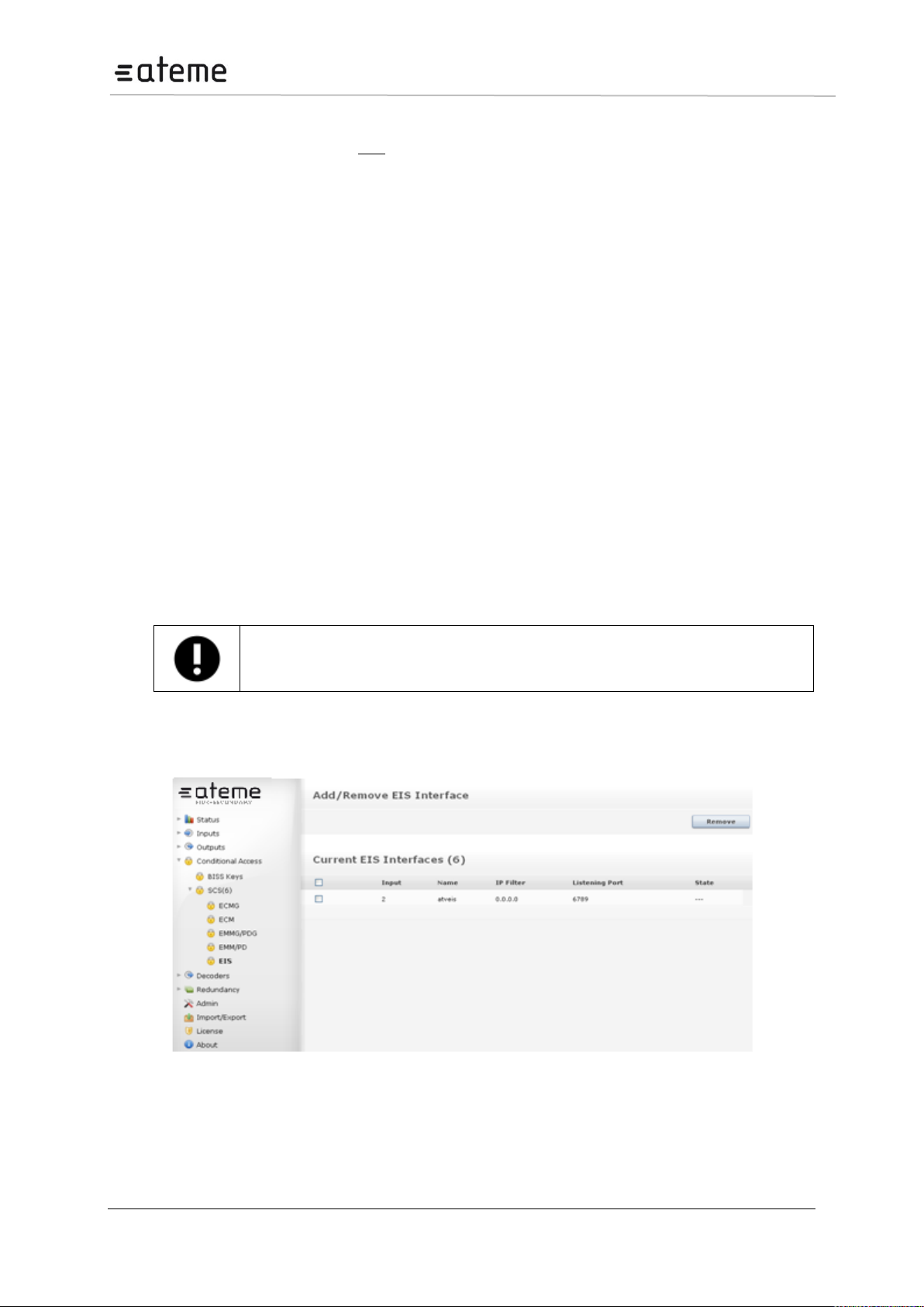
MC3x00 – User Manual
Based on the DVB Simulcrypt standard, only one EIS is permitted per chassis.
6.3.1.8 Support for Multiple CA Systems (Simulcrypt)
The scrambling solution supports four CA systems simultaneously. No particular configuration is
required for this. Simply define the appropriate ECMGs, ECMs, EMMGs and EMM connections
required. The system to be used for actual scrambling is defined as part of the output configuration
process.
When configuring services that are to contain information for multiple CA systems, the following must
be done:
The corresponding ECMs for each service / CA system must have identical SCG ID values
All ECMs must be assigned to the service
If applicable, valid EMMs must be added to the output for each CA system
6.3.1.9 Configuring an EIS service Channel
The Event Information Scheduling (EIS) interface is a scheduling interface for associating ECMs to
outputs. The configuration of the EIS is similar to setting up an ECMG/EMMG connection.
The EIS interface provides the following functions.
Create a new ECM
Modify an ECM’s access criteria
Remove an existing ECM
Control scrambling of an output service. The output triplet (Net ID, TS ID, and SID) is used as the
output service identifier.
As the EIS is not able to create the ECMG channel configuration, this needs to be done from the web
GUI before the EIS can be used.
To establish a connection to an EIS service, go to Scrambler SCS EIS node in the Navigation
Tree, enter appropriate values and click Add.
Figure 101 – Adding an EIS
The following information is displayed:
Page 97 / 213
Page 98
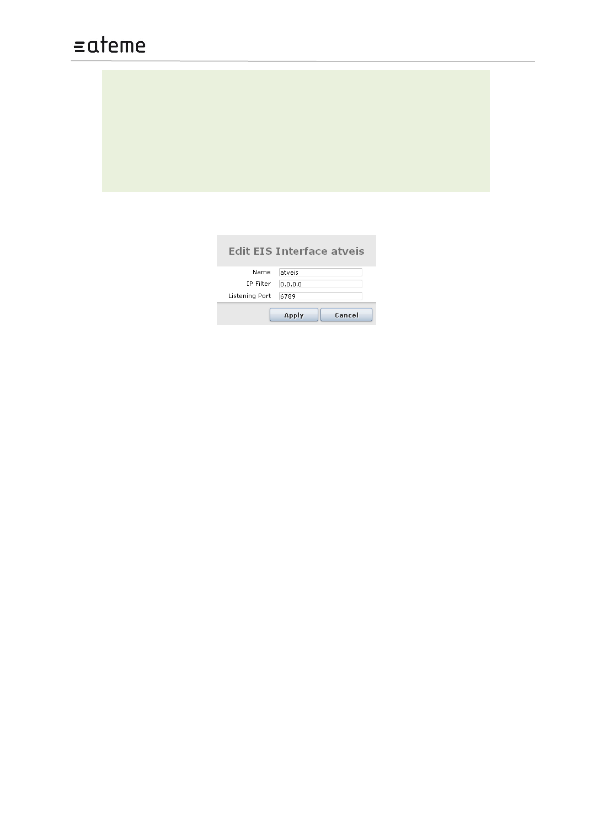
MC3x00 – User Manual
Input
Logical port representing the connection to the EMMG – assigned
automatically. This number is used internally as well as for generating
alarms.
Name
For reference in the GUI only
IP Filter
IP address of the EIS service to be connected to
Listening Port
TCP port for the EIS to connect to
State
OPEN or CLOSE
To change an, EIS connection, click on the existing EIS entry and enter the new configuration.
Figure 102 – Edit an EIS service
Once the service is connected, the EIS can schedule ECMs to the outputs.
Page 98 / 213
Page 99
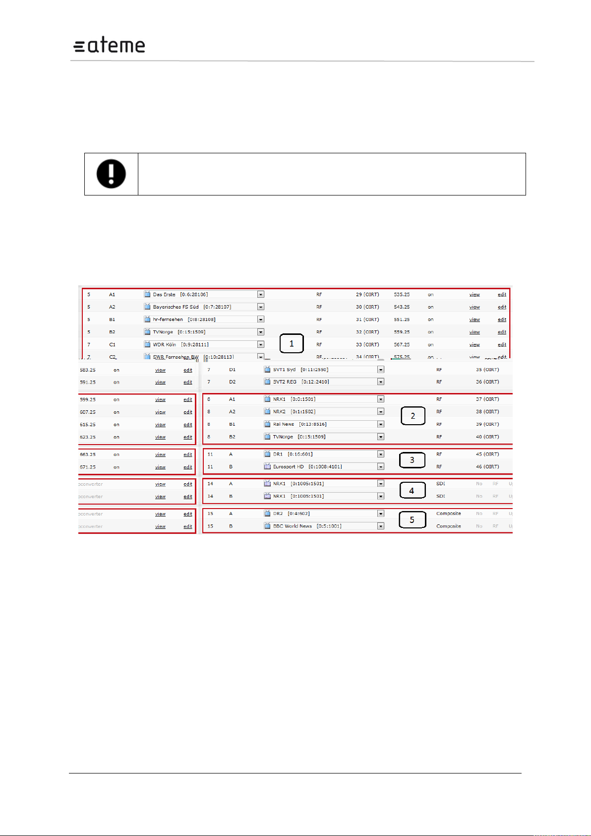
MC3x00 – User Manual
Refer to section 3.3.5 onwards for information on specific decoders and their features.
7 Decoder Output Configuration
The decoder modules are configured using the Decoders view in the Navigation Pane. All available
decoder modules will be listed based on their slot position.
7.1 Channel Configuration
The chassis can hold multiple dual decoder modules. Follow the procedure below to configure the
modules.
Open the Decoders view in the Navigation Pane and the window in Figure below will be displayed.
Figure 103 – Decoders Node
The different types of decoders are displayed in a different way:
8 channel quad decoders with TV modulators (the TV modulator is in slot 7)
4 channel quad decoders with TV modulators
Decoders with HP RF modulation and stereo
Decoders with SDI outputs
Decoder with Composite output
Page 99 / 213
Page 100
MC3x00 – User Manual
Slot
Slot position in the chassis
Output
Depending on the number of channels in the decoder, the channels are
identified in the following style:
Channel A and B for decoders with two channels
Channels A, B, C, and D for decoders with four channels
Channels A1, A2, B1, B2, C1, C2, D1, and D2 for decoders with eight
channels
Input Source
Assigns a service to the output. The service list is automatically generated
from the services available on the input modules. For an MPTS input stream,
all available services will be listed. If Service Definition Tables (SDTs) are
available in input streams, the service list will consist of service names
together with the Service ID (SID) and a local input ID. Whenever the SDT
table is not present, the services will be listed as service 1, service 2, etc.
RF Ch
Assigned RF channel with the frequency plan used displayed in brackets.
RF Freq
Assigned frequency in MHz
RF Enable
Shows if the channel is enabled or not; if it is not enabled the RF carrier is
switched off.
Status
Displays decoder status information. Refer to 0 for detailed information on the
parameters displayed.
Edit
Detailed configuration of the output
The RF parameters above will only be visible in the GUI if the decoder card has an RF
option. Otherwise, they will not be listed.
The Decoders page contains the following information:
To assign a service to an output, select it from the drop down list in the Service Name column.
Information such as the slot, input port, and service PID, for the corresponding input module can be
found just after the service name itself; the decoder’s type can be found in the About node.
The services will automatically be assigned to the output immediately after they have been selected.
To configure audio language, subtitling, etc, click Edit for the service/channel.
To view existing configuration for a particular decoder, click view in the Status column.
Page 100 / 213
 Loading...