

Page 1
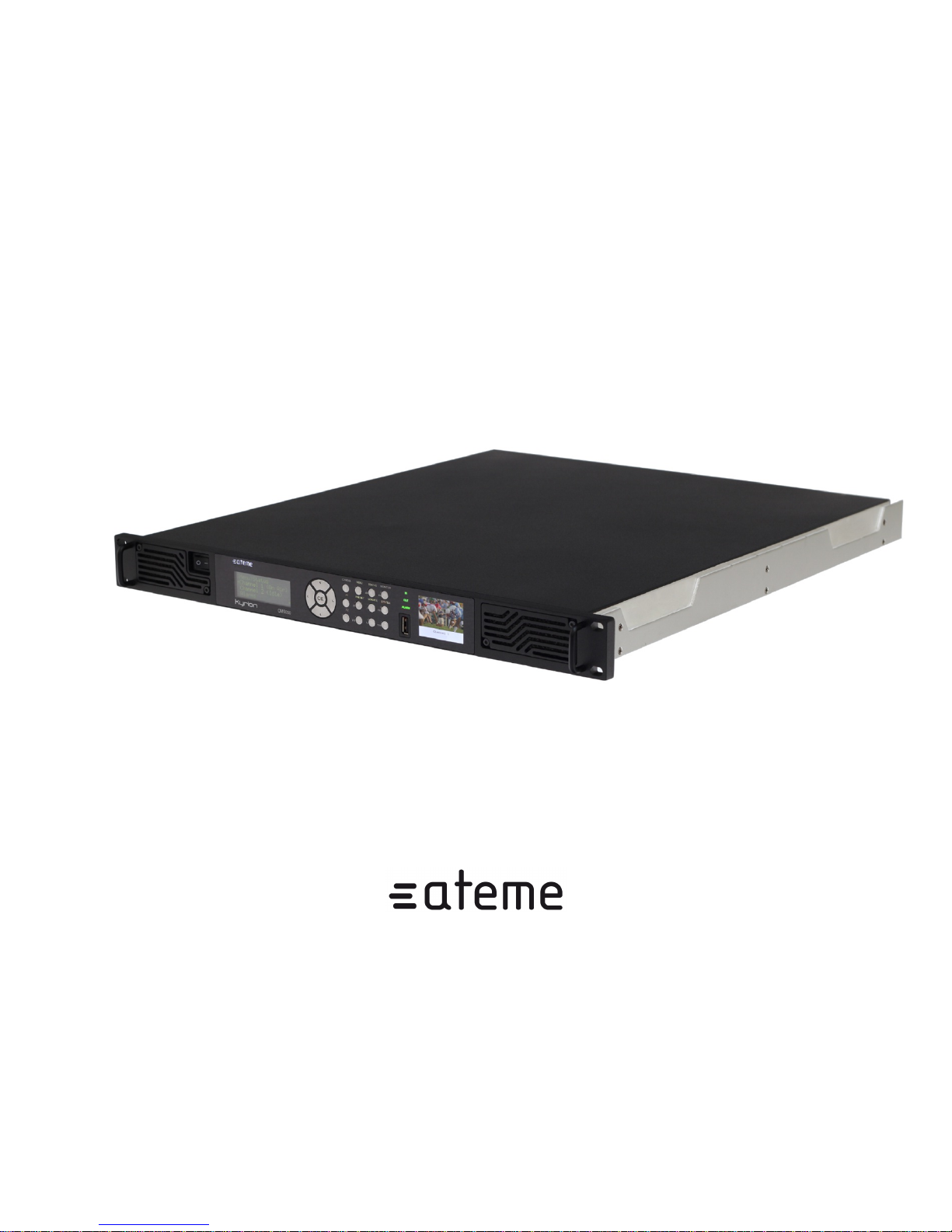
CM5000 - Modular
Contribution Encoder
users' manual
Page 2

CM5000 users' manual UM-CM5000-FW1.1-REV1.0
2012-10-30
Table of Contents
1. Document Overview ........................................................................................................ 7
1.1. Document identification ......................................................................................... 7
1.2. Disclaimer ........................................................................................................... 7
1.3. Copyrights .......................................................................................................... 7
1.4. Precautions .......................................................................................................... 8
2. Product Overview ........................................................................................................... 9
2.1. Package Content ................................................................................................... 9
2.2. Front View ........................................................................................................ 10
2.3. Rear View ......................................................................................................... 11
2.4. Power Switch ..................................................................................................... 12
2.5. I/O Base Interfaces ............................................................................................. 13
2.6. Extended Interfaces ............................................................................................. 14
2.6.1. Extended L-Band Modulator Interfaces ........................................................ 15
2.6.2. Extended IF Modulator Interfaces ................................................................ 16
2.6.3. Extended AES Audio Interfaces .................................................................. 18
2.6.4. Extended Analog Audio Interfaces .............................................................. 19
2.7. Serial Number .................................................................................................... 20
2.8. Ventilation ......................................................................................................... 21
3. Installation ................................................................................................................... 22
3.1. Hardware setup .................................................................................................. 22
3.2. Quick start ......................................................................................................... 23
4. User's Interfaces ............................................................................................................ 24
4.1. Three configuration tools ..................................................................................... 24
4.2. Front Panel ........................................................................................................ 24
4.2.1. Status LED ............................................................................................. 24
4.2.2. LCD ...................................................................................................... 25
4.2.3. TFT ....................................................................................................... 25
4.2.4. Keypad ................................................................................................... 25
4.2.5. Menu ..................................................................................................... 25
4.3. Web GUI .......................................................................................................... 29
4.3.1. Access setup ............................................................................................ 29
4.3.2. Web Based GUI Overview ......................................................................... 30
4.3.3. Status Tab ............................................................................................... 31
4.3.4. Channel Tab ............................................................................................ 31
4.3.5. System Tab ............................................................................................. 33
5. Settings ....................................................................................................................... 35
5.1. Preset Settings .................................................................................................... 35
5.1.1. Global .................................................................................................... 35
5.1.2. TS ......................................................................................................... 35
5.1.3. Output ASI ............................................................................................. 37
5.1.4. Output DVB-S/S2/DSNG ........................................................................... 37
5.1.5. Output IP ................................................................................................ 38
5.1.6. Video ..................................................................................................... 38
5.1.7. Audio ..................................................................................................... 41
5.1.8. Data ....................................................................................................... 42
5.2. System Settings .................................................................................................. 44
5.2.1. System - Miscellaneous ............................................................................. 44
5.2.2. System - Time ......................................................................................... 44
5.2.3. System - Network Interface ........................................................................ 44
5.2.4. System - Network VLAN .......................................................................... 45
5.2.5. System - Network Route ............................................................................ 45
www.ateme.com Page ii
Page 3

CM5000 users' manual UM-CM5000-FW1.1-REV1.0
2012-10-30
5.2.6. System - Alarms ...................................................................................... 45
5.2.7. System - Logs ......................................................................................... 46
5.2.8. System - SNMP Trap Target ...................................................................... 46
5.2.9. System - SNMP Password ......................................................................... 46
5.2.10. System - Statmux ................................................................................... 46
6. Specific Operations ....................................................................................................... 48
6.1. Installing License ................................................................................................ 48
6.2. Firmware management ......................................................................................... 48
6.3. Recovery ........................................................................................................... 49
A. Appendix .................................................................................................................... 51
A.1. Product's specification ......................................................................................... 51
A.2. Warranty .......................................................................................................... 61
A.3. Normative Reference .......................................................................................... 62
A.4. Glossary ........................................................................................................... 63
A.5. Support and Ressources ...................................................................................... 64
www.ateme.com Page iii
Page 4

CM5000 users' manual UM-CM5000-FW1.1-REV1.0
2012-10-30
List of Figures
2.1. Front View Interface ................................................................................................... 10
2.2. Rear View Interface .................................................................................................... 11
2.3. Power Switch ............................................................................................................. 12
2.4. I/O Base Interface ....................................................................................................... 13
2.5. Extended L-Band Modulator Interfaces ........................................................................... 15
2.6. Extended IF Modulator Interfaces .................................................................................. 16
2.7. Extended AES Audio Interfaces .................................................................................... 18
2.8. Extended Analog Audio Interfaces ................................................................................. 19
2.9. Serial Number and Production Code Markings ................................................................. 20
2.10. Cool air intakes on the front panel ............................................................................... 21
2.11. Warm air outputs on the rear panel .............................................................................. 21
4.1. Front Panel sub-elements' identification .......................................................................... 24
4.2. Log into the Web Server .............................................................................................. 30
4.3. Web Based Interface ................................................................................................... 31
4.4. WEB Based Interface - Status Tab ................................................................................. 31
4.5. WEB Based Interface - Channel Tab .............................................................................. 32
4.6. WEB Based Interface - System Tab ............................................................................... 33
4.7. Simple setting edition .................................................................................................. 33
4.8. Table setting edition .................................................................................................... 33
www.ateme.com Page iv
Page 5

CM5000 users' manual UM-CM5000-FW1.1-REV1.0
2012-10-30
List of Tables
1.1. Document Identification ................................................................................................ 7
2.1. Front View Interface ................................................................................................... 10
2.2. Rear View Interface .................................................................................................... 11
2.3. Power Switch ............................................................................................................. 12
2.4. I/O Base Interface ....................................................................................................... 13
2.5. Extended L-Band Modulator Interfaces ........................................................................... 15
2.6. Extended IF Modulator Interfaces .................................................................................. 16
2.7. Extended AES Audio Interfaces .................................................................................... 18
2.8. Extended Analog Audio Interfaces ................................................................................. 19
4.1. Status LED ................................................................................................................ 25
4.2. Front Panel Menu - Main ............................................................................................. 25
4.3. Front Panel Menu - Service Modulator ........................................................................... 27
4.4. Front Panel Menu - Service Main .................................................................................. 27
4.5. WEB Based Interface - Channel Tab Settings .................................................................. 32
4.6. WEB Based Interface - System Tab Settings .................................................................... 34
5.1. Global ...................................................................................................................... 35
5.2. TS ............................................................................................................................ 35
5.3. DVB compliance ........................................................................................................ 36
5.4. Carrier ID ................................................................................................................. 36
5.5. ATSC ....................................................................................................................... 36
5.6. Output ASI ................................................................................................................ 37
5.7. Output DVB-S/S2/DSNG ............................................................................................. 37
5.8. Output IP .................................................................................................................. 38
5.9. Video ....................................................................................................................... 38
5.10. MPEG-4 AVC .......................................................................................................... 39
5.11. MPEG-4 AVC-I ........................................................................................................ 40
5.12. MPEG-2 .................................................................................................................. 40
5.13. Audio ...................................................................................................................... 41
5.14. MPEG Layer2 .......................................................................................................... 42
5.15. AAC ....................................................................................................................... 42
5.16. Dolby Digital ........................................................................................................... 42
5.17. Data ........................................................................................................................ 42
5.18. Teletext and VBI teletext descriptor ............................................................................. 43
5.19. Teletext and VBI teletext filter .................................................................................... 43
5.20. VBI ........................................................................................................................ 43
5.21. DVB Subtitles .......................................................................................................... 43
5.22. DVB Subtitles descriptor ............................................................................................ 43
5.23. Miscellaneous ........................................................................................................... 44
5.24. Time ....................................................................................................................... 44
5.25. Interface .................................................................................................................. 44
5.26. VLAN ..................................................................................................................... 45
5.27. Route ...................................................................................................................... 45
5.28. Alarms .................................................................................................................... 45
5.29. Logs ....................................................................................................................... 46
5.30. Trap target ............................................................................................................... 46
5.31. Passwords ................................................................................................................ 46
5.32. Statmux ................................................................................................................... 46
A.1. Specification - Identification ........................................................................................ 51
A.2. Specification - Physical ............................................................................................... 51
A.3. Specification - Environmental and Power ....................................................................... 51
A.4. Specification - Certifications ........................................................................................ 51
www.ateme.com Page v
Page 6

CM5000 users' manual UM-CM5000-FW1.1-REV1.0
2012-10-30
A.5. Specification - Configuration and Management ................................................................ 51
A.6. Specification - Video Input .......................................................................................... 52
A.7. Specification - Audio Input .......................................................................................... 52
A.8. Specification - Data Input ............................................................................................ 53
A.9. Specification - Black Burst-3Level and ASI Synchronization .............................................. 53
A.10. Specification - Filter ................................................................................................. 53
A.11. Specification - Specification - Video Processing ............................................................. 54
A.12. Specification - Audio Processing ................................................................................. 55
A.13. Specification - Specification - Data Processing .............................................................. 55
A.14. Specification - Muxer ................................................................................................ 56
A.15. Specification - Output ............................................................................................... 56
A.16. Specification - L-Band or IF Modulator ........................................................................ 57
A.17. Specification - System ............................................................................................... 59
A.18. Normative reference .................................................................................................. 62
A.19. Glossary ................................................................................................................. 63
www.ateme.com Page vi
Page 7
CM5000 users' manual UM-CM5000-FW1.1-REV1.0
1. Document Overview
1.1. Document identification
Table 1.1. Document Identification
Title CM5000 - Modular Contribution Encoder - users' manual
Revision Number 1.0
Description Document for firmware release 1.1
Date of Issue 2012-10-30
Document Reference UM-CM5000-FW1.1-REV1.0
1.2. Disclaimer
2012-10-30
The material in this document is for information only and subject to change without notice. While reasonable efforts have been made in the preparation of this document to assure its accuracy, ATEME assumes
no liability resulting from errors or omissions in this document, or from the use of the information contained herein. ATEME reserves the right to make changes or revisions in the product design or the product
manual without reservation and without obligation to notify any person of such revisions and changes.
1.3. Copyrights
Notice
The ATEME Kyrion(R) is not designed or intended to violate any other entity's copyright or other IP (Intellectual Property) rights. Each ATEME Kyrion(R) user may only use their ATEME Kyrion(R) in conjunction with materials legally owned or licensed by such user, and only to the extent that such ownership
or license rights permit such use.
Copyright (c) 2011-2012 ATEME
These materials, ATEME products and all related documentation are protected by copyright and other
laws, international treaties and conventions. All rights, title and interest in the materials, ATEME products
and related documentation shall remain with ATEME and its licensors. All registered or unregistered
trademarks in these materials are the sole property of their respective owners. No part of this document or
related ATEME products may be reproduced in any form, or by any means without written authorization
of ATEME Corporation.
These materials are provided "as-is." ATEME makes no warranties, stated or implied, as to, the information
contained herein. In addition, ATEME makes no stated or implied warranties of merchantability or working
condition for a particular purpose or use with respect the information contained in these materials.
www.ateme.com Page 7
Page 8
In no event shall ATEME be liable for any indirect, special, consequential or incidental damages, including,
but not limited to, lost profits or loss or damage to data arising from the use of these materials, even if
advised in advance of the possibility of such damages.
The glossary of this document is partially extracted from the Wikipedia encyclopedia: Copyright (c)
ATEME
Trademarks
ATEME, the ATEME logo, Kyrion(R) and the KYRION(R) logo are all trademarks or registered trademarks of ATEME Corporation. The Kyrion(R) clustering technology -as well as other technologies included in Kyrion(R) - are protected by patents or pending patent applications in the U.S. and other countries. All other trademarks or registered trademarks are property of their respective owners.
1.4. Precautions
Only qualified persons are authorized to carry out maintenance on this device.
CM5000 users' manual UM-CM5000-FW1.1-REV1.0
2012-10-30
Read the Users' Manual carefully, and follow the correct procedure when setting up the device.
Do not open your Kyrion or attempt to disassemble or modify it, unless instructed by an ATEME repre-
sentative. To avoid any risk of electrical shock, fire, short-circuiting or dangerous emissions, never insert
any metallic object into the enclosure. Your Kyrion contains no user-serviceable parts. If it appears to be
malfunctioning, have it inspected by a qualified ATEME Technical Support representative.
Never expose your device to rain, use it near water, or in damp or wet conditions. Never place objects
containing liquids on the Kyrion, as they may spill into its openings; doing so increases the risk of electrical
shock, short-circuiting, fire or personal injury.
Basic electrical safety precautions should be followed to protect you from harm and the system from
damage:
• Be aware of where the On/Off power switch is situated on the chassis; as well as the rack's emergency
power off- switch. Check also where the disconnection switch or electrical outlet is located.
• Do not work alone when working with high voltage components.
• Power should always be disconnected from the system before opening it. When disconnecting the power,
you should first power down the system and unplug the power cords of the power supply.
• Only the provided power supply cord must be use to power the Kyrion. This power supply cord includes
a grounding plug and it must be plugged into a grounded electrical outlet. If you should use a different
power supply cord, make sure it is compatible with your locale electrical power supply.
www.ateme.com Page 8
Page 9

CM5000 users' manual UM-CM5000-FW1.1-REV1.0
2. Product Overview
2.1. Package Content
Before continuing, please check the content of the product package. This product package should contain
the following items:
• One (1) Kyrion(R) CM5000,
• One (1) Power Cord,
• One (1) CD ROM,
• This User's Manual.
If anything is missing, please contact your place of purchase.
2012-10-30
www.ateme.com Page 9
Page 10
2.2. Front View
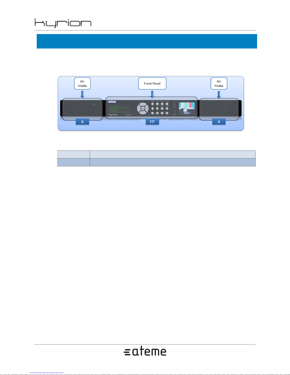
Next picture describes the front interface of the Kyrion(R) CM5000.
Figure 2.1. Front View Interface
Table 2.1. Front View Interface
FP Front Panel
A Air Intakes
CM5000 users' manual UM-CM5000-FW1.1-REV1.0
2012-10-30
Front Panel Interfaces FP are described in Section 4.2, “ Front Panel ”
Ventilation using Air Intakes A is described in Section 2.8, “ Ventilation ”
www.ateme.com Page 10
Page 11
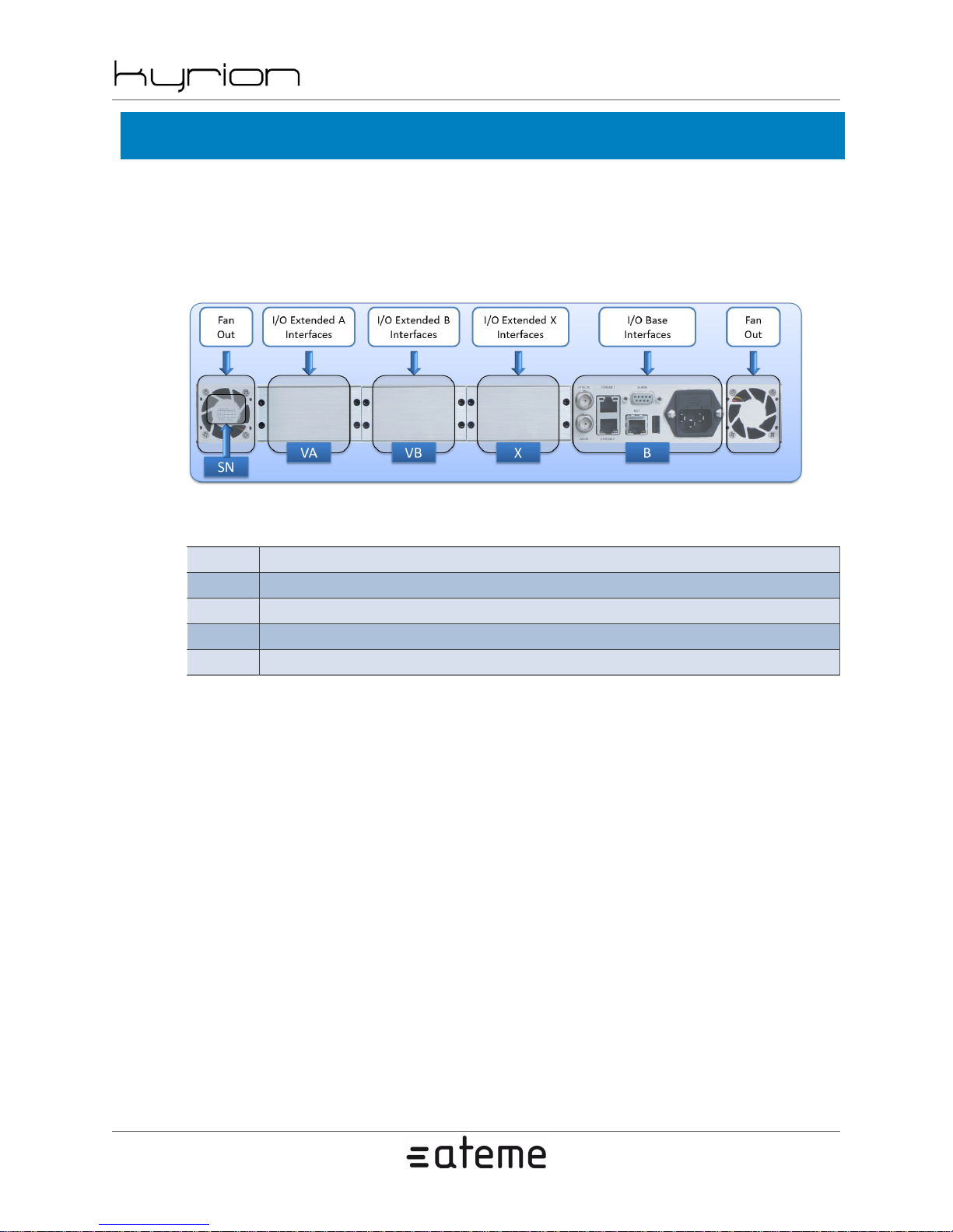
2.3. Rear View
Next picture describes the generic rear interfaces of Kyrion(R) Encoders.
Depending on your exact model and the options purchased, the extended slots may contain additional
connectors which will be described in the next paragraphs.
Figure 2.2. Rear View Interface
CM5000 users' manual UM-CM5000-FW1.1-REV1.0
2012-10-30
Table 2.2. Rear View Interface
B I/O Base Interfaces
X I/O Extended X Interfaces
VA I/O Extended A Interfaces
VB I/O Extended B Interfaces
SN Serial Number and Product Code
www.ateme.com Page 11
Page 12
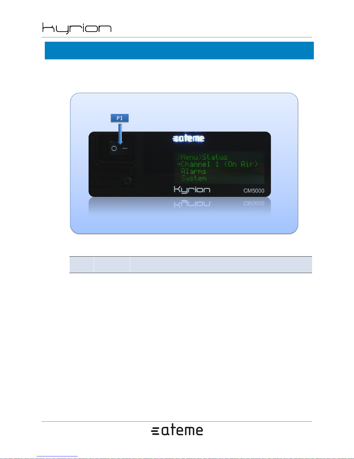
2.4. Power Switch
Next figure describes the location of the Power switch of the Kyrion(R) CM5000.
Figure 2.3. Power Switch
CM5000 users' manual UM-CM5000-FW1.1-REV1.0
2012-10-30
Table 2.3. Power Switch
P1 Power Switch
Use this switch to turn ON the unit. Switch it
back to the original position to turn OFF the unit.
www.ateme.com Page 12
Page 13
CM5000 users' manual UM-CM5000-FW1.1-REV1.0
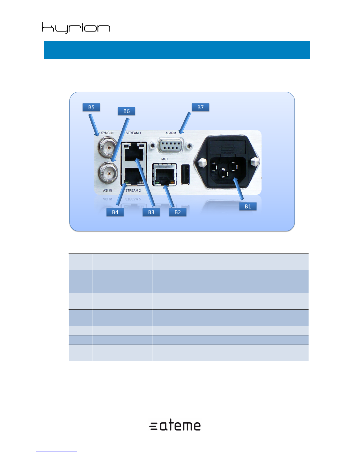
2.5. I/O Base Interfaces
Next figure describes the I/O Base interfaces of the Kyrion(R) CM5000.
Figure 2.4. I/O Base Interface
2012-10-30
Table 2.4. I/O Base Interface
B1 AC Inlet (~AC)
B2
B3
B4
B5 Synchro In Connector This BNC Connector is dedicated to synchronize the encoder.
B6 ASI In Connector This BNC Connector is dedicated to input ASI stream.
B7 ALARM Connector
MGT Ether-
net Connector
STREAM Ether-
net Connector 1
STREAM Ether-
net Connector 2
This Ethernet connector is dedicated for streaming encoded
video over IP. This interface is a Gigabit Ethernet port (1Gbps).
Connect the provided cable to this inlet.
The Kyrion(R) auto detects AC voltage.
This dedicated Ethernet connector allows adminis-
tration of the Kyrion(R) via the Web or SNMP. This
interface is a 1000Base-T Ethernet port (1Gbps).
Same as [B3].
This DB9 connector is dedicated to
input and output discrete signals.
www.ateme.com Page 13
Page 14

CM5000 users' manual UM-CM5000-FW1.1-REV1.0
2.6. Extended Interfaces
Depending of the hardware options that you purchased, some of the next interfaces may be accessible on
I/O Extended Interfaces ([X], [VA], [VB]).
2012-10-30
www.ateme.com Page 14
Page 15
CM5000 users' manual UM-CM5000-FW1.1-REV1.0
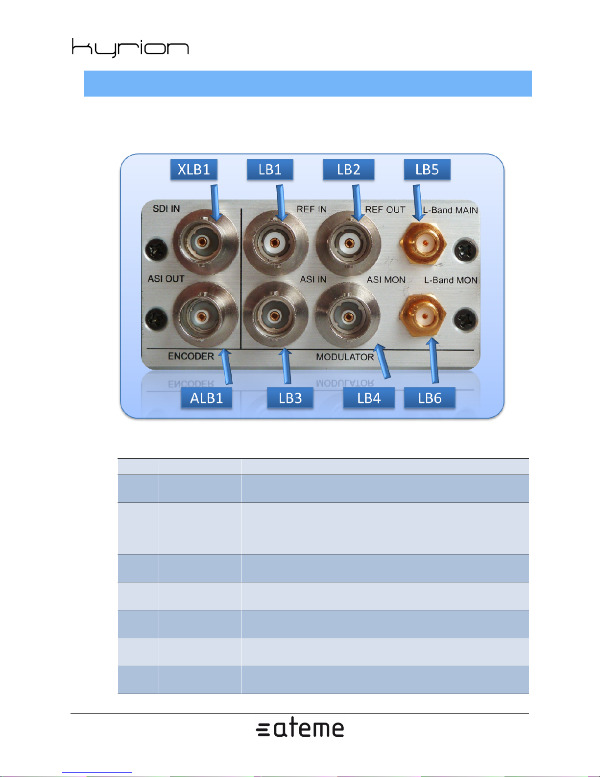
2.6.1. Extended L-Band Modulator Interfaces
Next figure describes the Extended L-Band Modulator interfaces of the Kyrion(R) CM5000.
Figure 2.5. Extended L-Band Modulator Interfaces
2012-10-30
Table 2.5. Extended L-Band Modulator Interfaces
XLB1 Encoder SDI IN Use this BNC connector to input the SDI video signal into the Encoder.
ALB1 Encoder ASI OUT
LB1 Modulator REF IN
LB2
LB3 Modulator ASI IN
LB4
LB5
LB6
Modulator
REF OUT
Modulator
ASI MON
Modulator L-
Band MAIN
Modulator L-
Band MON
Use this BNC connector to output the encoded bitstream. It
should be connected to the ASI input of the Modulator [LB3].
Use this connector to input the external 10MHz reference
frequency used by the Modulator. The modulator can ei-
ther used this external reference frequency or a 10MHz in-
ternal reference frequency (selection trough GUI interface)
This connector outputs the 10MHz ref-
erence frequency used by the Modulator.
Use this BNC connector to input the ASI
stream to be modulated by the Modulator.
This connector outputs a monitoring
copy of the ASI stream to be modulated.
This connector outputs the modulated signal to
be connected to the emitting system (0 dBm).
This connector outputs the modulated signal to be con-
nected to an analyzing or monitoring system (-20 dBm).
www.ateme.com Page 15
Page 16
CM5000 users' manual UM-CM5000-FW1.1-REV1.0
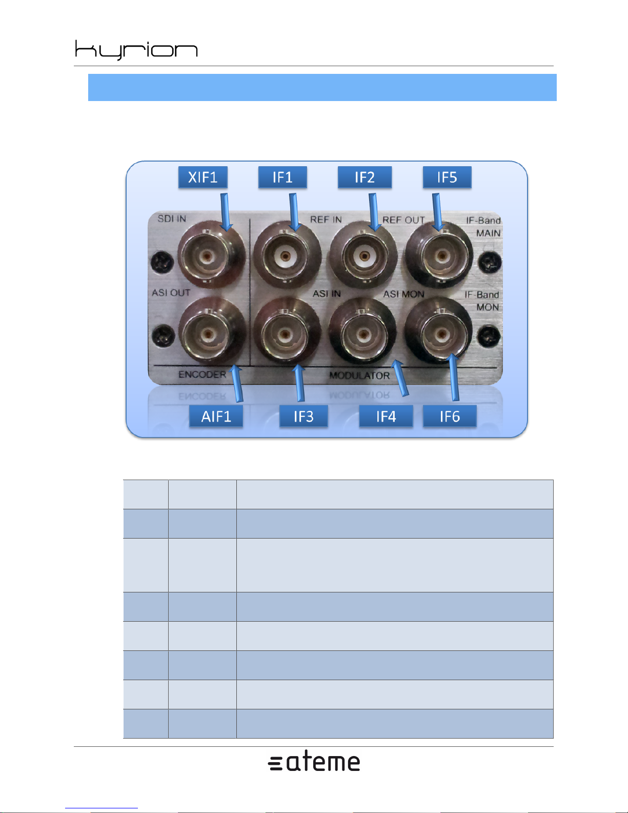
2.6.2. Extended IF Modulator Interfaces
Next figure describes the Extended IF Modulator interfaces of the Kyrion(R) CM5000.
Figure 2.6. Extended IF Modulator Interfaces
2012-10-30
Table 2.6. Extended IF Modulator Interfaces
XIF1
AIF1
IF1
IF2
IF3
IF4
IF5
IF6
Encoder
SDI IN
Encoder
ASI OUT
Modula-
tor REF IN
Modulator
REF OUT
Modula-
tor ASI IN
Modulator
ASI MON
Modulator
IF MAIN
Modulator
IF MON
Use this BNC connector to input the SDI video signal into the Encoder.
Use this BNC connector to output the encoded bitstream. It
should be connected to the ASI input of the Modulator [IF3].
Use this connector to input the external 10MHz reference
frequency used by the Modulator. The modulator can ei-
ther used this external reference frequency or a 10MHz in-
ternal reference frequency (selection trough GUI interface)
This connector outputs the 10MHz ref-
erence frequency used by the Modulator.
Use this BNC connector to input the ASI
stream to be modulated by the Modulator.
This connector outputs a monitoring
copy of the ASI stream to be modulated.
This connector outputs the modulated signal to
be connected to the emitting system (0 dBm).
This connector outputs the modulated signal to be con-
nected to an analyzing or monitoring system (-20 dBm).
www.ateme.com Page 16
Page 17

CM5000 users' manual UM-CM5000-FW1.1-REV1.0
2012-10-30
www.ateme.com Page 17
Page 18
CM5000 users' manual UM-CM5000-FW1.1-REV1.0
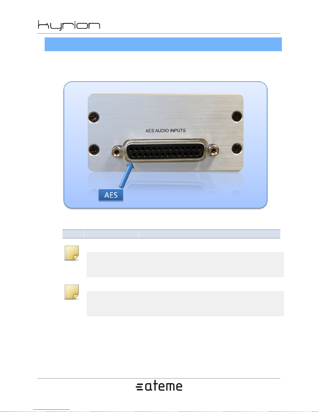
2.6.3. Extended AES Audio Interfaces
Next figure describes the AES Audio extended interface of the Kyrion(R) CM5000.
Figure 2.7. Extended AES Audio Interfaces
2012-10-30
Table 2.7. Extended AES Audio Interfaces
AES AES Audio Input Use this DB25 connector to input up to 8 AES audio pairs.
Note
To input audio with XLR connectors, use the XLR to DB25 cable provided separately (Ref :
AEXT-CBL).
Note
In the System/Extension boards menu of the WEB GUI, the AES Audio Extended Interface
board is identified as "AUDIO AES".
www.ateme.com Page 18
Page 19
CM5000 users' manual UM-CM5000-FW1.1-REV1.0
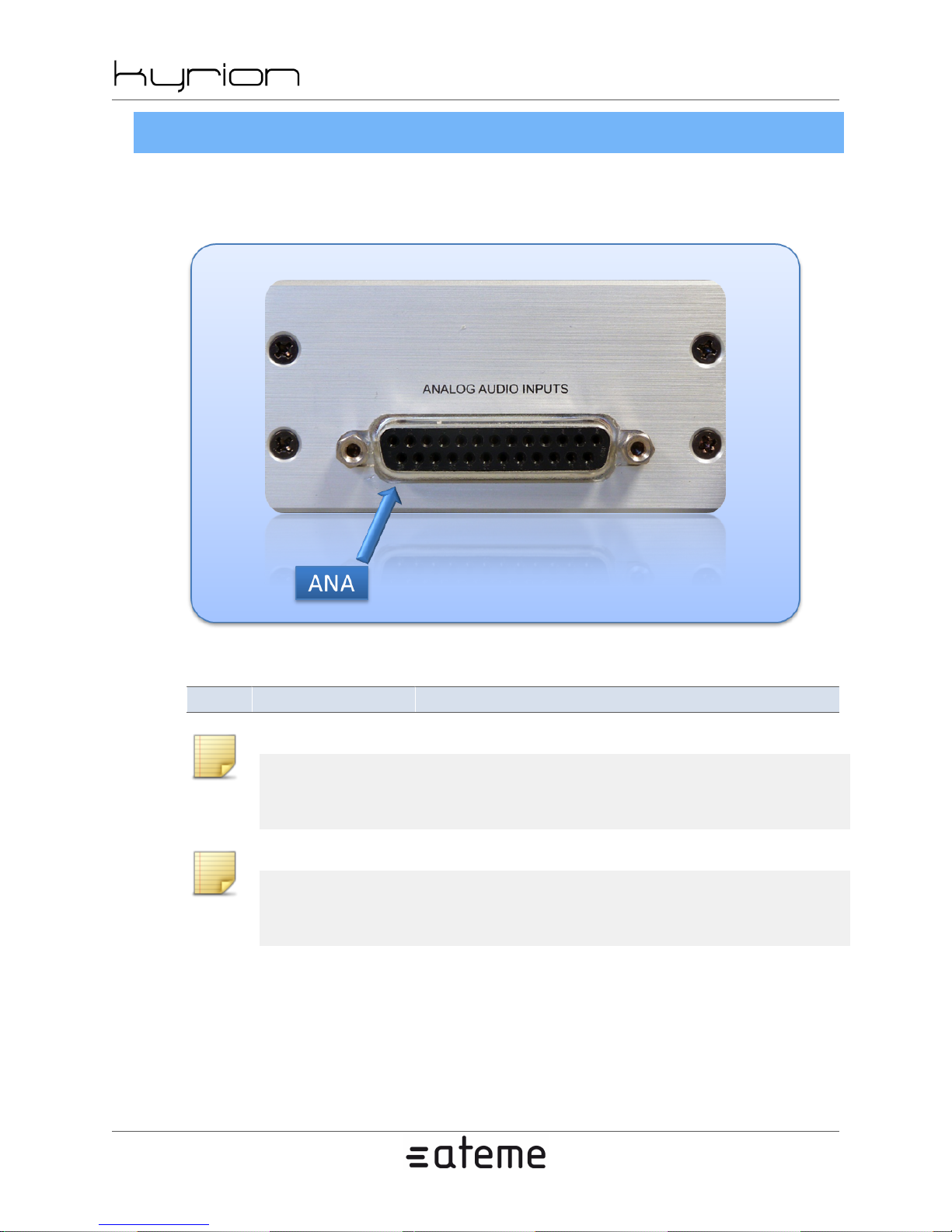
2.6.4. Extended Analog Audio Interfaces
Next figure describes the Analog Audio extended interface of the Kyrion(R) CM5000.
Figure 2.8. Extended Analog Audio Interfaces
2012-10-30
Table 2.8. Extended Analog Audio Interfaces
ANA Analog Audio Input Use this DB25 connector to input up to 4 analog audio pairs.
Note
To input audio with XLR connectors, use the XLR to DB25 cable provided separately (Ref :
AEXT-CBL).
Note
In the System/Extension boards menu of the WEB GUI, the Analog Audio Extended Interface board is identified as "AUDIO ANALOG".
www.ateme.com Page 19
Page 20
CM5000 users' manual UM-CM5000-FW1.1-REV1.0
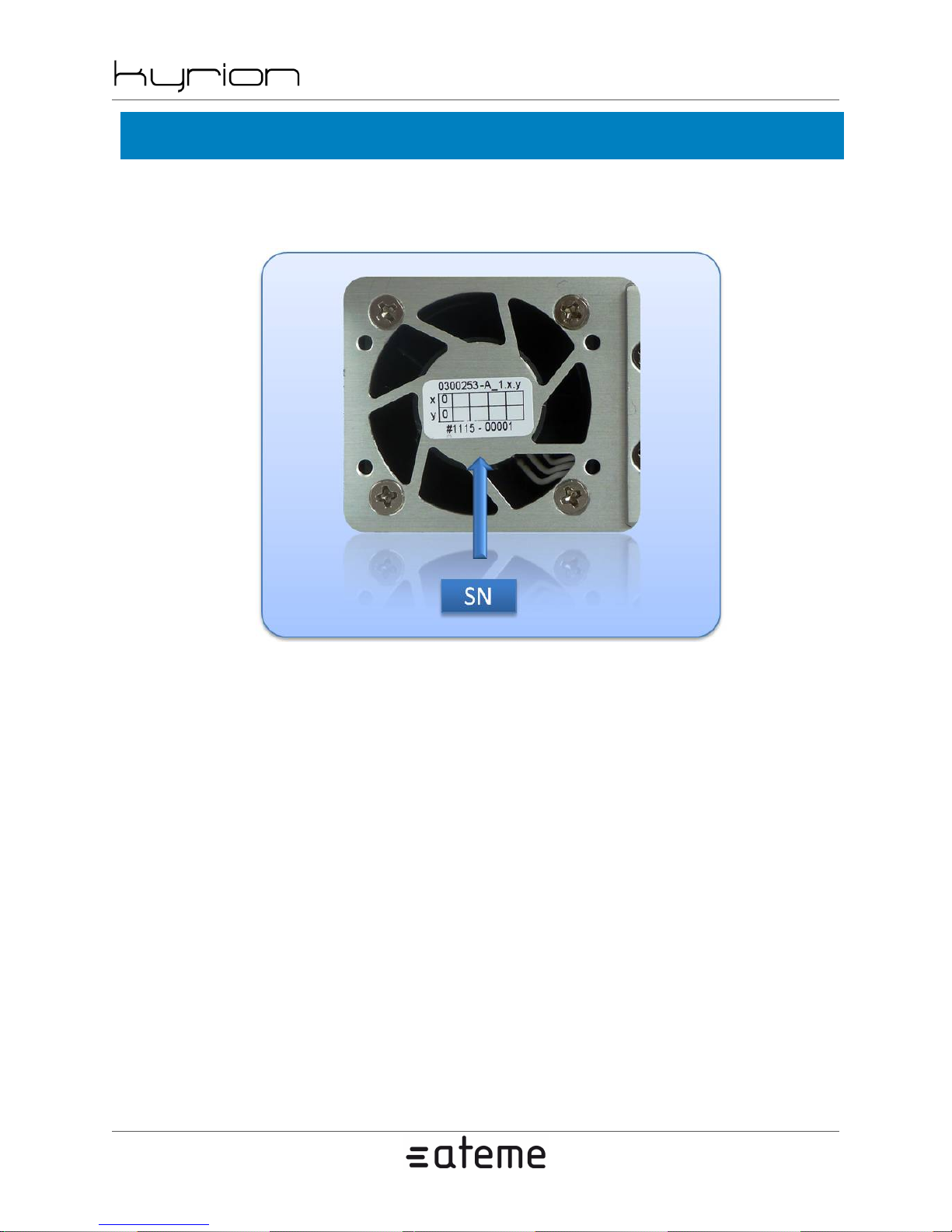
2.7. Serial Number
Serial Number and Production Code Markings are located in the rear side [SN].
Figure 2.9. Serial Number and Production Code Markings
2012-10-30
www.ateme.com Page 20
Page 21
2.8. Ventilation
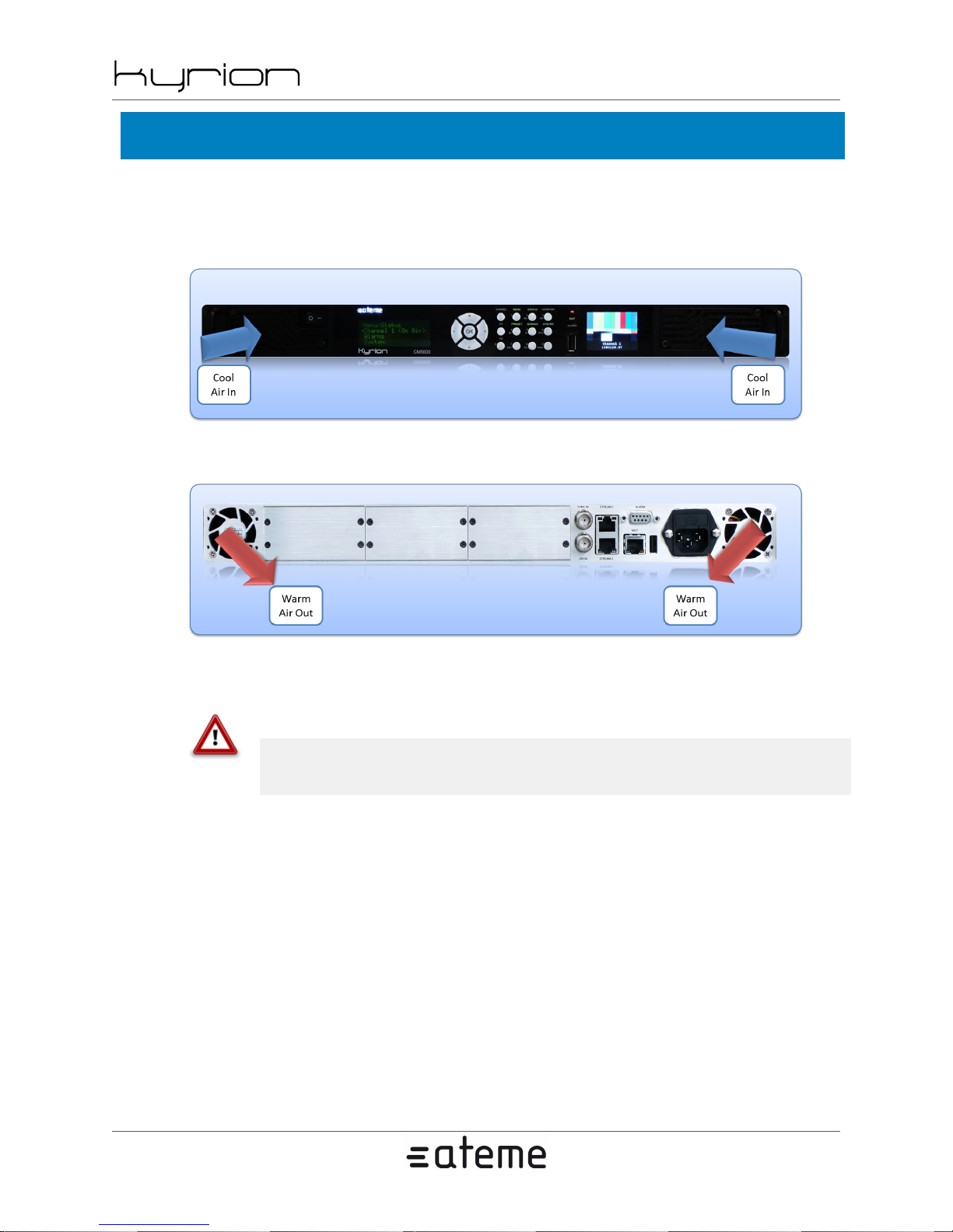
Air ventilation prevents abnormal temperature rises inside the unit. Next figures show cool air intakes and
warm air outputs.
Figure 2.10. Cool air intakes on the front panel
Figure 2.11. Warm air outputs on the rear panel
CM5000 users' manual UM-CM5000-FW1.1-REV1.0
2012-10-30
Place the Kyrion(R) in a well-ventilated space, and allow ideally up to 10cm of free space on all sides of
the Kyrion(R) so increasing air circulation and cooling.
Warning
Never obstruct air intakes and outtakes. Beware of 19'' bays doors, if any.
www.ateme.com Page 21
Page 22
CM5000 users' manual UM-CM5000-FW1.1-REV1.0
3. Installation
3.1. Hardware setup
Step 1: Unpack and install the Kyrion(R)
Unpack your Kyrion(R) unit and install it.
• For Stand Alone installation, place the unit on a stable surface. It requires clearance above and on each
side to allow cooling.
• Alternatively, for Rack installation, mount the unit in a standard 19-inch rack. The Kyrion(R) requires
1U of vertical space.
Note
Note for Rack installation : Carefully slide the Kyrion(R) into a shelf space in the rack. Use
your equipment rack's screws to secure the device in place, in the rack.
2012-10-30
Step 2: Connect the power
Connect the Kyrion(R) input power [B1] to a power outlet using the provided power cord.
Step 3: Connect to Ethernet
Connect the network cables to Ethernet interfaces.
• The Stream interfaces [B3] and [B4] should be plugged into your broadcast network
• The MGT interface [B2] should be plugged into your supervision network
Note
If you do not have different networks, using the streaming port to do both broadcasting and
administration is possible. This is not recommended for production phases.
Step 4: Connect SDI input
Connect the HD-SDI input cables to [X1] (see Section 2.3, “ Rear View ”).
Step 5: Power up
Power up the Kyrion(R), switching the 0/1 button [P1] into the position 1.
www.ateme.com Page 22
Page 23

CM5000 users' manual UM-CM5000-FW1.1-REV1.0
• After a few seconds, a BOOTING message should appear on the LCD.
• The front panel selection menu appears when the unit is up and running.
3.2. Quick start
Step 1 : Configure management IP address
Use the front panel to configure the MGT IP address of the encoder: [Kyrion IP address] (System ->
Network -> MGT -> IP).
Step 2 : Open a web browser
On a computer connected to the same network, launch your favourite web browser and browse to http://
[Kyrion IP address].
Step 3 : Login
2012-10-30
An authentication popup may appear. In this case, type 'admin' as username and 'admin' as password
(default login).
Step 4 : Configure the encoder
Go to the Channel 1 tab, configure the TS bitrate, the video format and an output, click on 'Apply'.
Step 5 : Start the encoder
Go to the Status tab, click on 'Start'.
www.ateme.com Page 23
Page 24
CM5000 users' manual UM-CM5000-FW1.1-REV1.0
4. User's Interfaces
4.1. Three configuration tools
There are 3 different ways to configure your Kyrion(R):
• Front Panel access (see Section 4.2, “ Front Panel ”),
• Web-based interface (see Section 4.3, “ Web GUI ”),
• SNMP.
the Web based interface gives access to all the parameters but need a network connection to be used. The
Front Panel interface gives access to all the operational parameters and most of the system ones. Choose
the most appropriate way depending on your overall system’s design.
4.2. Front Panel
2012-10-30
The Kyrion(R) has a local LCD and keypad interface allowing a simple management of the unit.
The control buttons and LCD provide an easy method of setting the network interface addresses and default gateway parameters directly from the front of the Kyrion(R) System without using a management
computer.
No IT knowledge is required and the Kyrion(R) can be up and running in minutes.
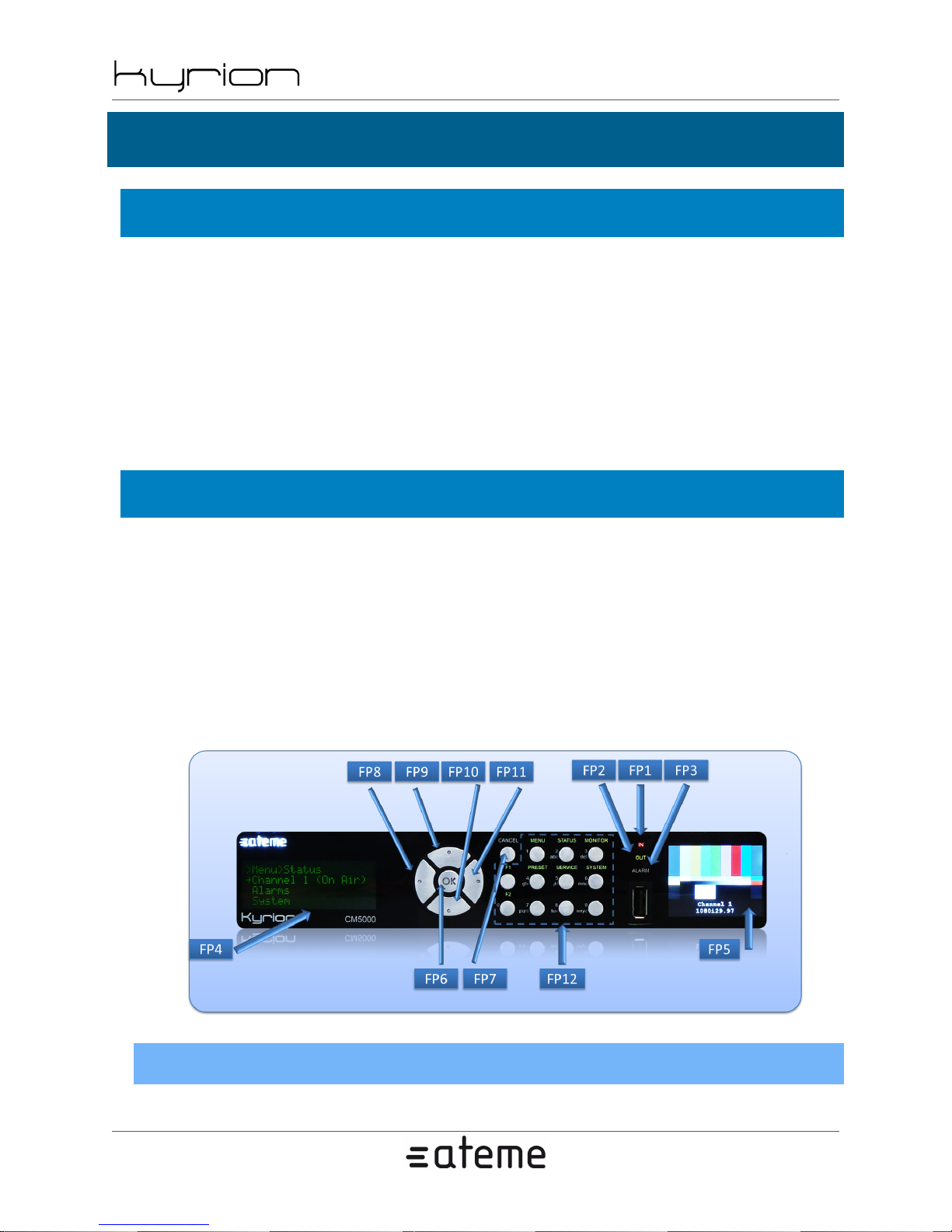
Next figure describes the front panel sub-elements' identification.
Figure 4.1. Front Panel sub-elements' identification
4.2.1. Status LED
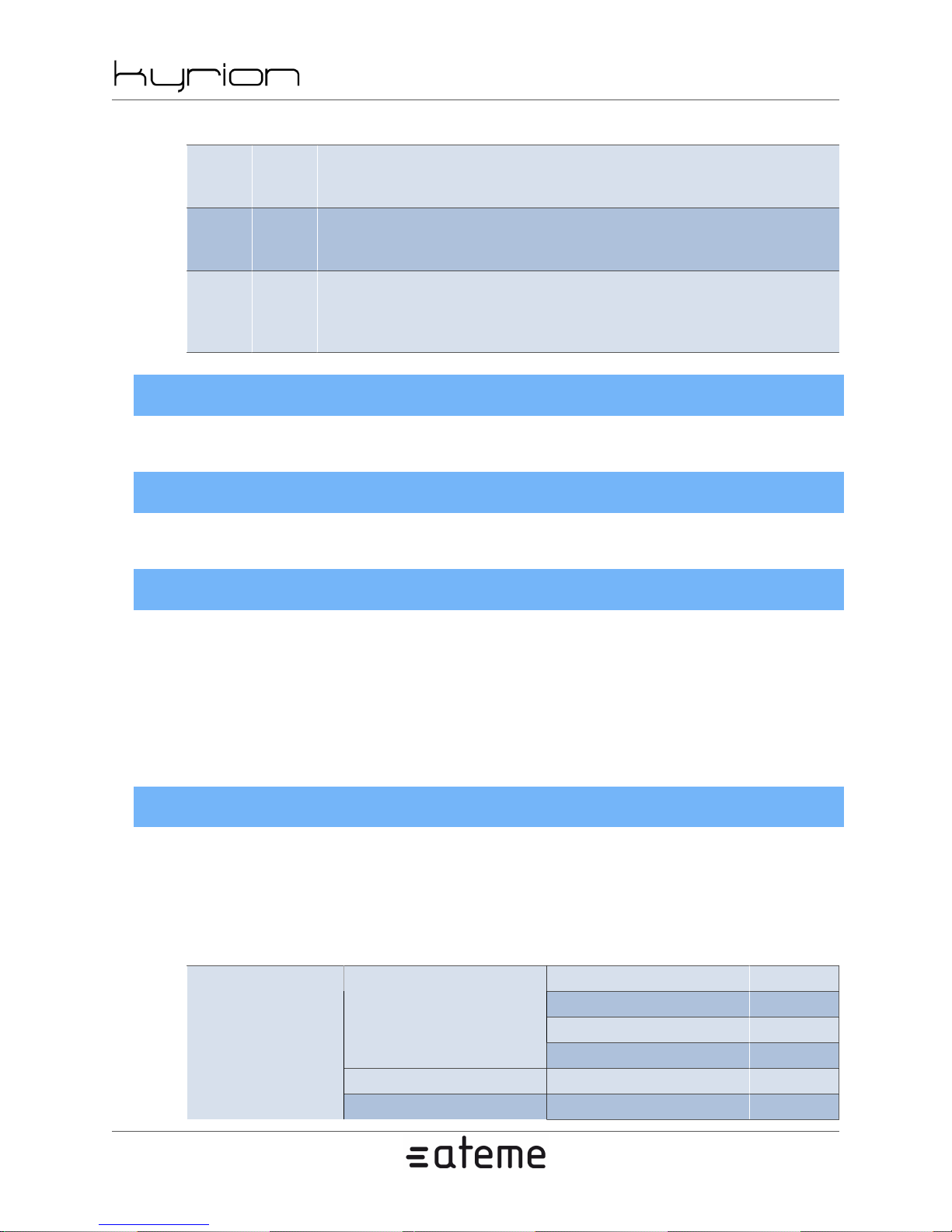
The Kyrion(R) comes with a complete range of LEDs that report the device status.
www.ateme.com Page 24
Page 25
CM5000 users' manual UM-CM5000-FW1.1-REV1.0
Table 4.1. Status LED
Off : Encoder idle
FP1 IN
FP2 OUT
FP3 ALARM
Solid Red: Encoder hardware error or malfunction detected
Solid Green : Valid input signal
Solid Orange : No input signal
Off : Encoder idle
Solid Green : Valid output signal
Solid Orange : Invalid output signal
Off : No Status
Solid Green: Encoder hardware is OK
Solid Orange: Warning
4.2.2. LCD
The LCD [FP4] displays some status information and configuration menus.
4.2.3. TFT
2012-10-30
The TFT [FP5] displays the video input signal and its format.
4.2.4. Keypad
The Keypad is used for configuration when navigating the local setup menu of the Kyrion(R).
Use the directional keys, [FP8] to [FP11] , to navigate through the different menus.
Use the 'OK' key [FP6] to validate changes and the 'Cancel' key [FP7] to cancel any action.
Depending on the context, use the extended keys [FP12] to enter characters, numbers or as a shortcut to
some menus.
4.2.5. Menu
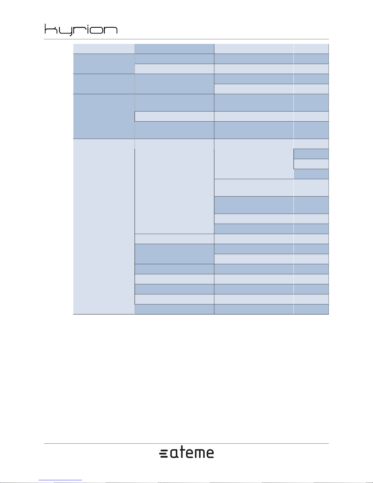
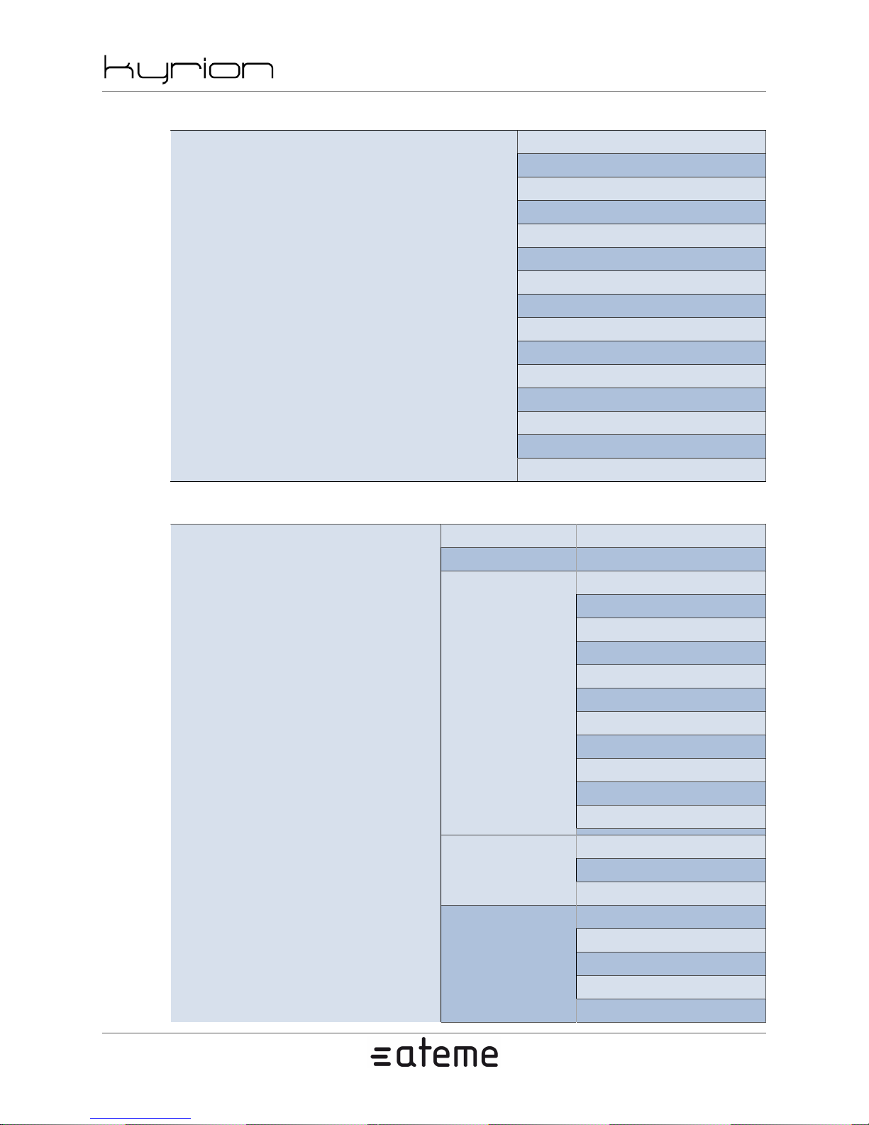
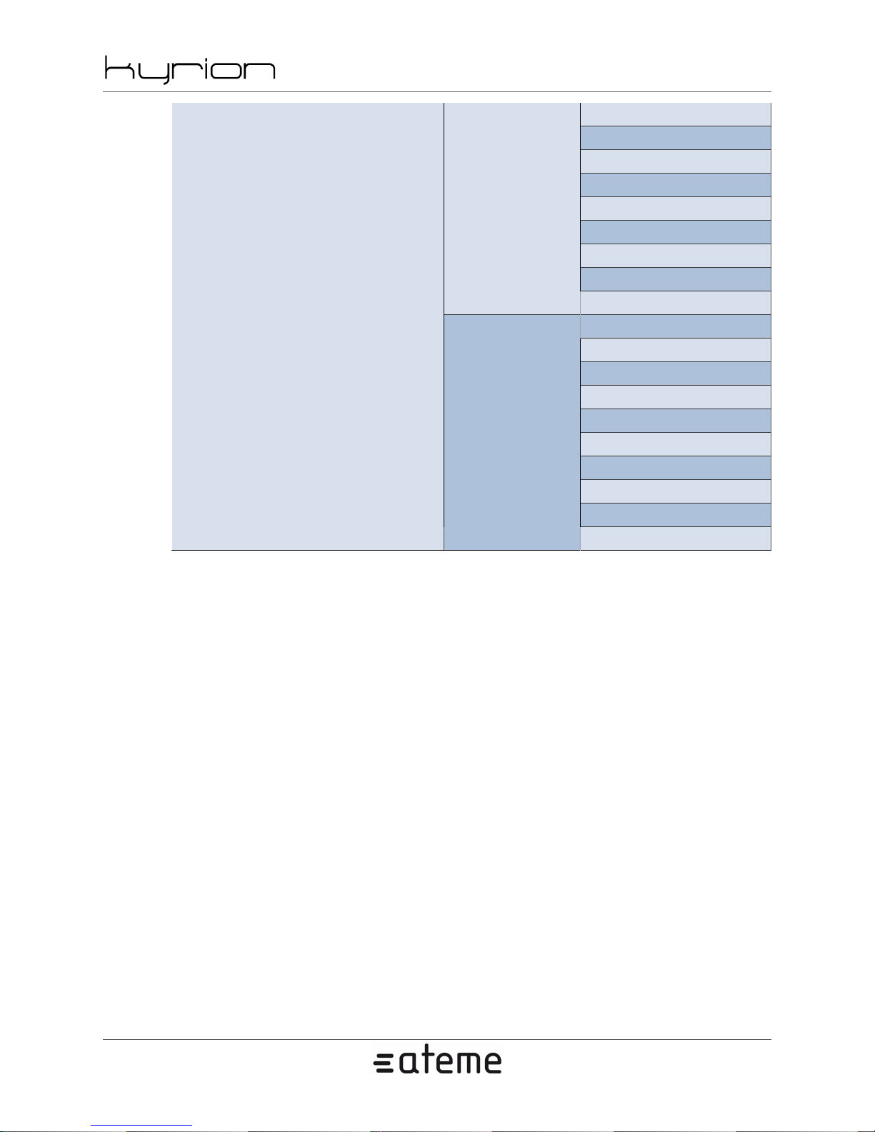
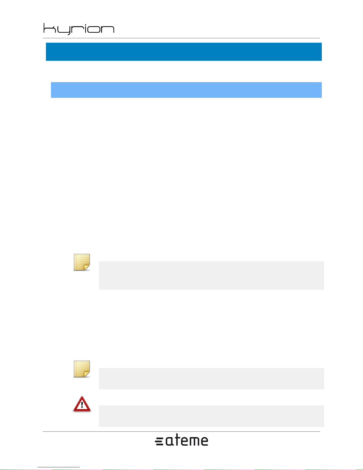
This chapter lists all the parameters that can be set through the front panel interface. Some are not accessible
depending on your product or the licenses that you purchased.
See the product specification in annexes to check capability of your product.
Table 4.2. Front Panel Menu - Main
TS -
Channel 1
Status
Alarms - System
Output -
Video Audio -
Temperature -
www.ateme.com Page 25
Page 26
CM5000 users' manual UM-CM5000-FW1.1-REV1.0
Channel - -
Monitor
SD Aspect Ratio - -
Preset Channel 1
Modulator
Name - -Service
Main
Network
System
Reboot - -
Software
Hardware SN -
BISS-E ID F1 Key Assignment - F2 Key Assignment - -
Name - -
Uptime -
Load From Slot -
Save To Slot -
Table 4.3, “Front Panel
Menu - Service Modulator”
Table 4.4, “Front Pan-
el Menu - Service Main”
MGT
Stream 1
Stream 2
Default Gateway -
Reset Routes -
Version -
Build -
2012-10-30
-
-
Mode
IP
Net Mask
Speed
(same as
MGT)
(same as
MGT)
www.ateme.com Page 26
Page 27
CM5000 users' manual UM-CM5000-FW1.1-REV1.0
Table 4.3. Front Panel Menu - Service Modulator
Service Modulator
2012-10-30
Enabled
Transmit
Mode
Output Power (dBm)
BUC's LOF (MHz)
Frequency (MHz)
Symbol Rate (MBd)
Standard
Type
FEC
Roll-off
Frame Type
Pilot mode
Spectral Inversion
10 MHz Clock Ref
Table 4.4. Front Panel Menu - Service Main
Quality/Latency
Service Main
Enabled
TS
Video
Bitrate (kbps)
BISS
Standard
Min Null (kbps)
PAT
PMT
CAT
Packet Size
SI/PSIP Tables
DVB-SI Tables
ATSC-PSIP Tables
Modulator
ASIOutput
Ip 1
Input
Format
MPEG-4 AVC
MPEG-2
TS PID
www.ateme.com Page 27
Page 28
CM5000 users' manual UM-CM5000-FW1.1-REV1.0
2012-10-30
Enabled
Format
MPEG Layer 2
AAC
Audio 1
Dolby Digital
SMPTE 302M
Input
TS
Processing
Enabled
Input
Processing
Format
Teletext
Data 1
VBI
SCTE-35
DVB Subtitles
SMPTE-2038
TS
www.ateme.com Page 28
Page 29
4.3. Web GUI
With the web-based interface you have access to all the parameters.
4.3.1. Access setup
Ethernet connection
Connect the Kyrion(R) MGT interface B2 to an Ethernet connection.
You can either:
• use a cross-over Ethernet cable to connect the devices directly to the controlling computer,
• use straight through Ethernet cables to connect the devices to a hub or switch.
Configure both the management computer and Kyrion(R) to be on the same subnet. To do this, two solu-
tions are possible:
CM5000 users' manual UM-CM5000-FW1.1-REV1.0
2012-10-30
• change the IP address of the management computer to 192.168.128.2 (for example) and the netmask
to 255.255.255.0
• or change the Kyrion(R) network parameters to match your network architecture.
Since you are probably not starting on the same sub-nets, it is necessary to use the front panel interface
at first boot.
Note
To access the Kyrion(R) web-based manager, start any Web browser and browse to
http://192.168.128.1 This is the Factory default IP address of the MGT port.
Log into the Web Server
First of all, you will have to log into the Web server. To do so, enter the following URL in your browser:
http://[Kyrion IP Address].
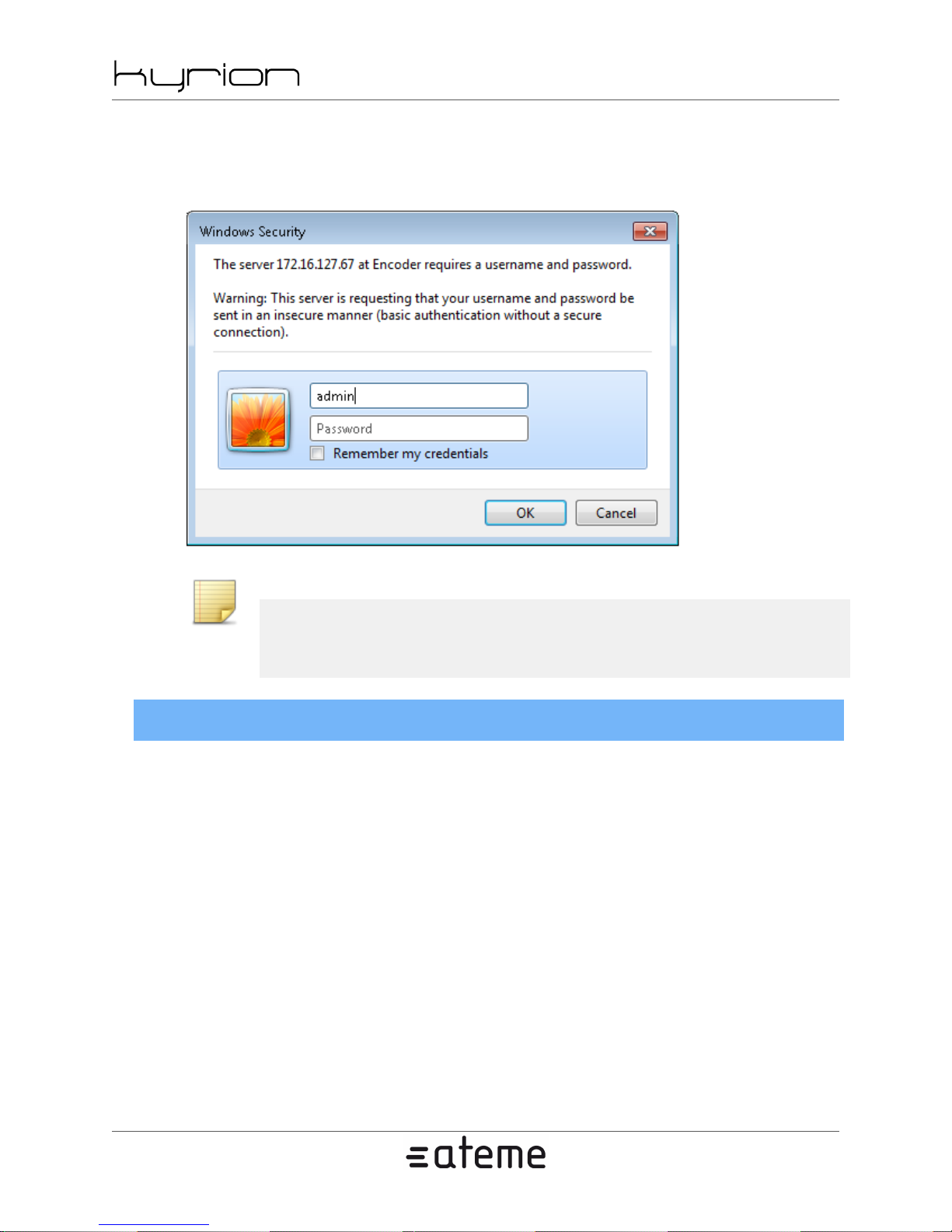
Depending on the Kyrion(R) configuration, a popup may appear, asking for a Login and a Password (see
Figure 4.2, “Log into the Web Server”). In this case, login is 'admin' and factory default password is 'admin'.
Note
Only password can be modified. Login is always 'admin'.
Warning
Password and login are case sensitive.
www.ateme.com Page 29
Page 30
CM5000 users' manual UM-CM5000-FW1.1-REV1.0
2012-10-30
Login protection and the associated password can be configured in the System tab of the Web interface
(see Section 4.3.5, “ System Tab ”).
Figure 4.2. Log into the Web Server
Note
The login dialog box will be displayed in your OS language. It may be different that the
above figure.
4.3.2. Web Based GUI Overview
Once logged in, the Web server of the Kyrion(R) will display its management environment.
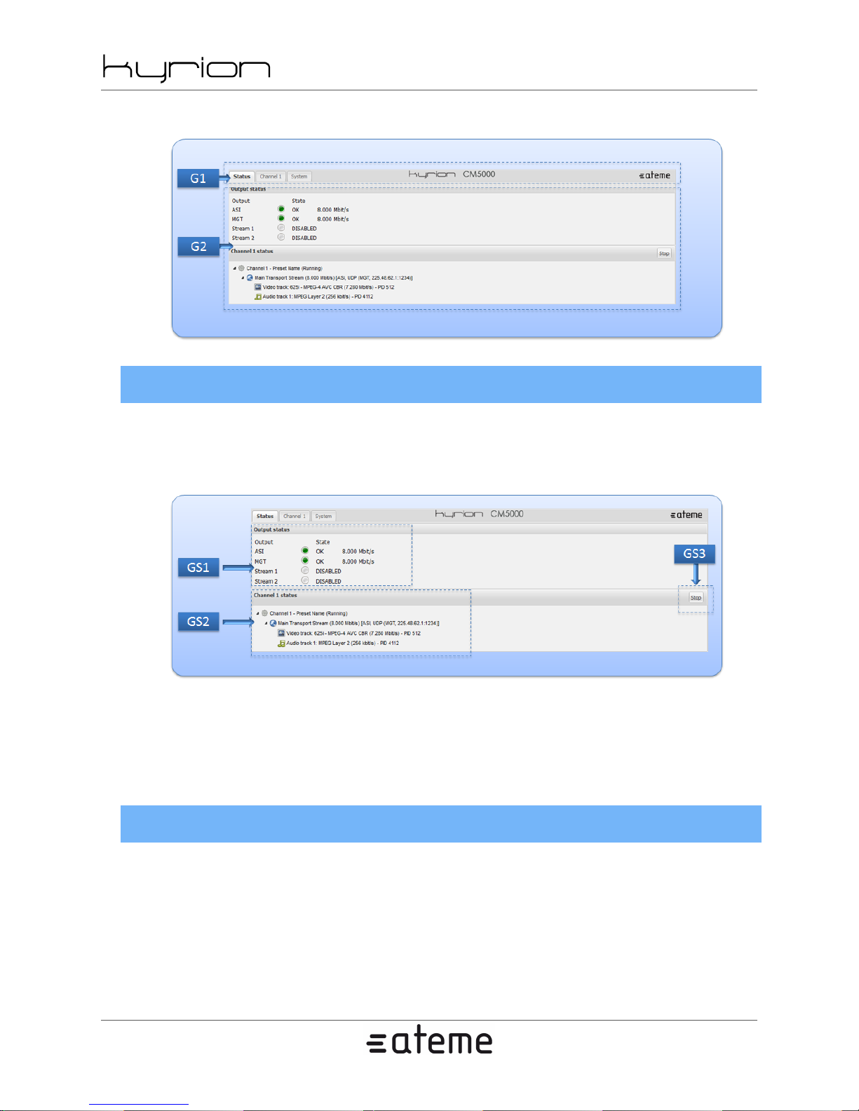
This environment is divided into 2 main areas:
• Navigation bar G1. Use this navigation bar to access all the parameters. Clicking on each Tab of this
navigation bar will update the Active Area located just below.
• Active Area G2. Displays the parameters associated with the current Tab.
www.ateme.com Page 30
Page 31
CM5000 users' manual UM-CM5000-FW1.1-REV1.0
Figure 4.3. Web Based Interface
4.3.3. Status Tab
This Tab is used to monitor the status of the encoder channels.
2012-10-30
Figure 4.4. WEB Based Interface - Status Tab
• [GS1]: Outputs state summary.
• [GS2]: Channel state summary.
• [GS3]: Button used to Start or Stop a channel.
4.3.4. Channel Tab
This Tab allows to view, configure, import and export the settings associated to a channel. Each channel
is managed independently of the other ones.
www.ateme.com Page 31
Page 32
CM5000 users' manual UM-CM5000-FW1.1-REV1.0
2012-10-30
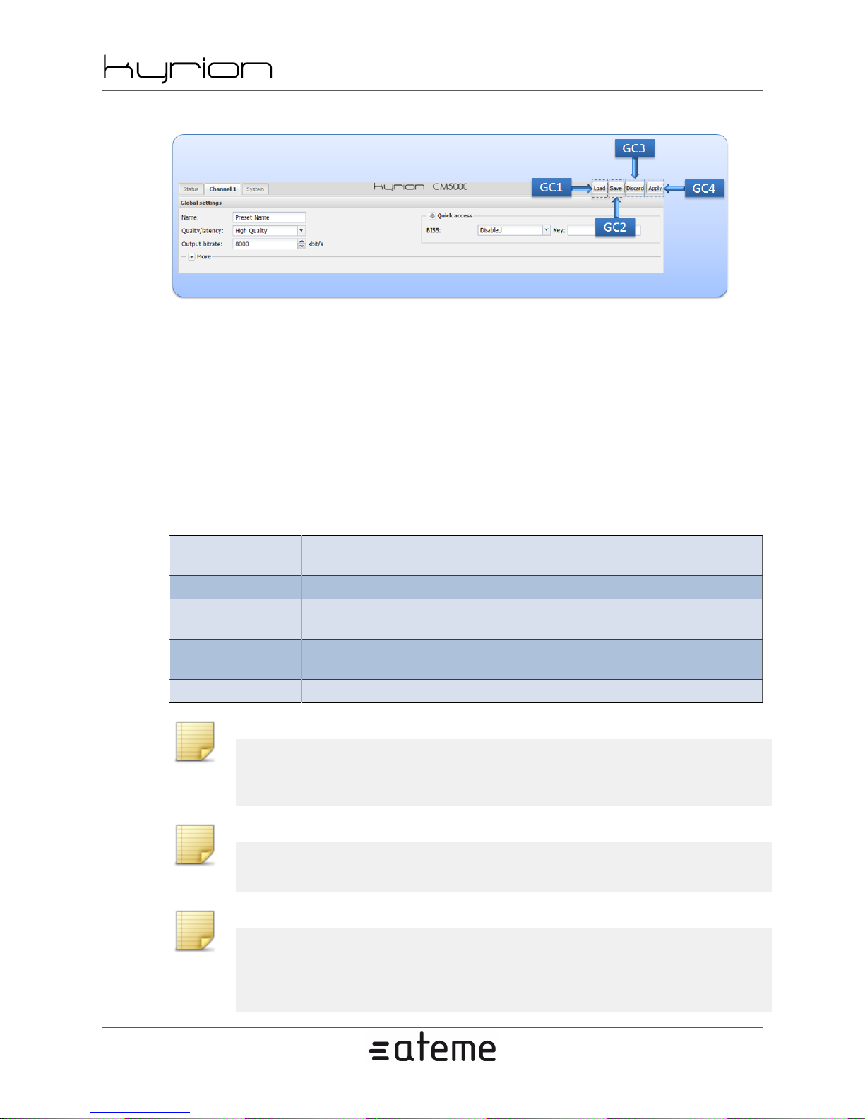
Figure 4.5. WEB Based Interface - Channel Tab
• [GC1]: Button used to load a preset into the web GUI editor. The preset can be loaded from a file, from
slots stored on the Kyrion(R) or from a preset using factory settings. This action does not disrupt nor
reconfigure the encoder.
• [GC2]: Button used to save the content of the web GUI editor to a file or to a slot stored on the Kyrion(R).
• [GC3]: Button used to discard non applied changes done on the web GUI editor. After this action, the
web GUI editor will show the settings that are being used by the encoder.
• [GC4]: Button used to apply changes done on the web GUI editor. After this action, the encoder will
use the new settings.
Table 4.5. WEB Based Interface - Channel Tab Settings
Global settings
Output settings Settings that apply to the output (eg: ASI, DVB-S, IP)
Video settings
Audio settings
Data settings Settings that apply to the data stream (eg: Teletext properties, DVB subtitles...)
Settings that apply to the whole transport stream
(eg: Quality/latency trade-off, TS bitrate, BISS...)
Setting that apply to the video acquisition and stream
(eg: SDI input format, codec, Closed caption...)
Settings that apply to the audio acquisi-
tion and stream (eg: SDI group/pair, codec...)
Note
You can safely navigate away from this tab without losing your changes even if some of
them are unapplied.
Note
Unapplied changes are visually identified by a light orange outline.
Note
If you want to import a preset from a file to a slot, you can load it using [GC1], then save
it using [GC2]. Afterward, you may optionally use the discard button [GC3] to show the
settings the encoder is using.
www.ateme.com Page 32
Page 33
CM5000 users' manual UM-CM5000-FW1.1-REV1.0
4.3.5. System Tab
This tab allows you to configure the system settings, monitor and manage the equipment.
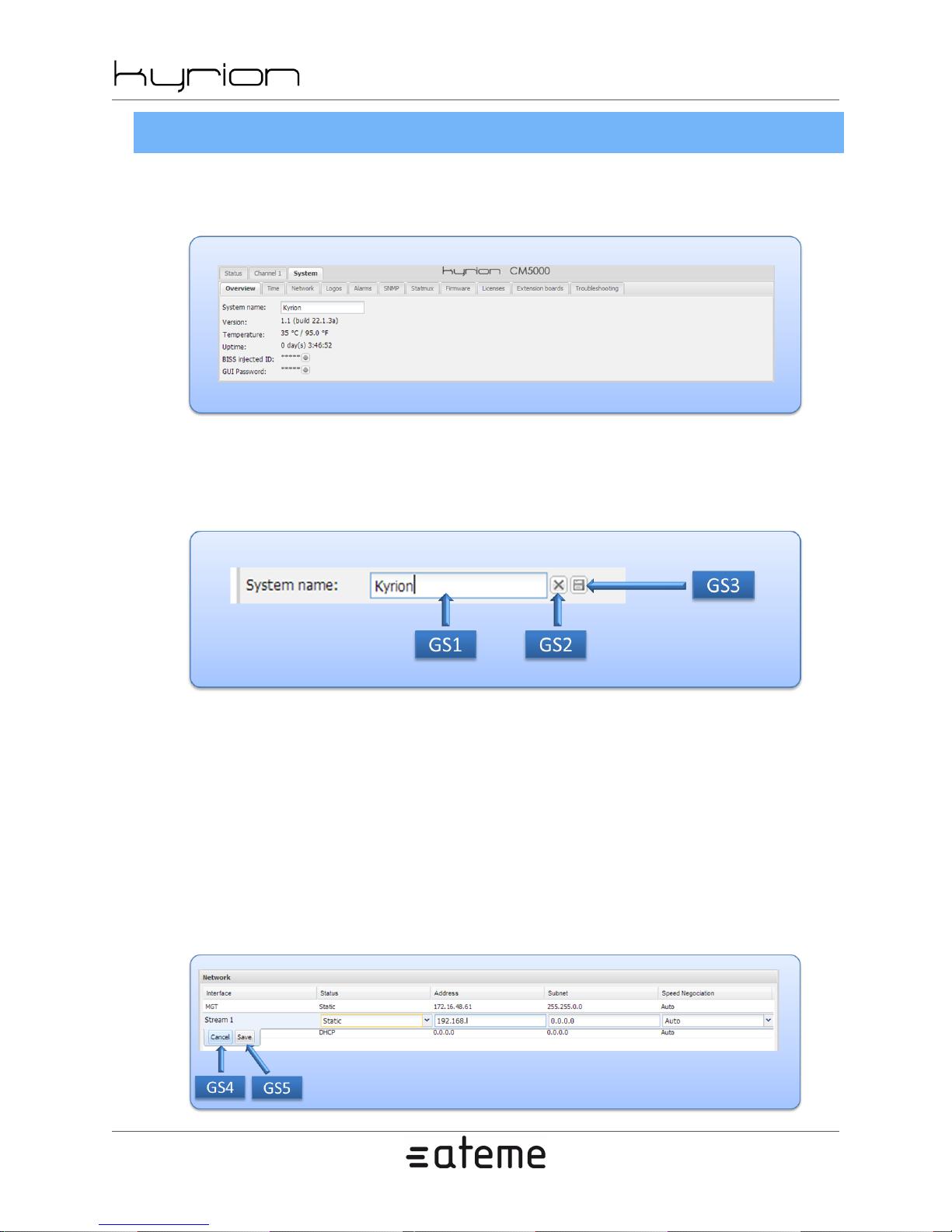
Figure 4.6. WEB Based Interface - System Tab
Simple setting edition
Figure 4.7. Simple setting edition
2012-10-30
To edit a simple setting, you can:
• Click on [GS1] to enter the edition mode. The buttons [GS2] and [GS3] appear.
• Update the value in [GS1].
• Click on [GS3] to apply your change or on [GS2] to cancel your change. The buttons [GS2] and [GS3]
disappear.
Table setting edition
Figure 4.8. Table setting edition
www.ateme.com Page 33
Page 34
CM5000 users' manual UM-CM5000-FW1.1-REV1.0
2012-10-30
To edit one or multiple settings of a line in a table:
• Click on the setting you want to edit. The buttons [GS4] and [GS5] appear. They apply for the whole line.
• Update the values on the line.
• Click on [GS5] to apply your changes or on [GS4] to cancel them.
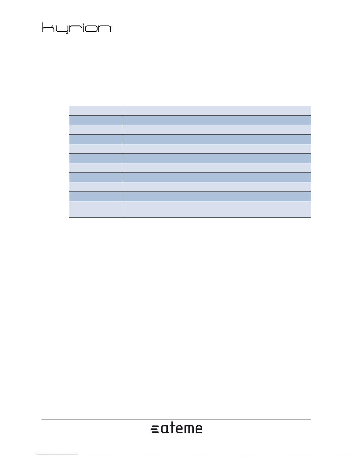
Table 4.6. WEB Based Interface - System Tab Settings
Overview General information about the Kyrion(R).
Time Time settings (Time, GMT offset, NTP server).
Network Network settings (Network interface, VLAN, route).
Logos Logo management.
Alarms Alarms settings.
SNMP SNMP settings (Trap targets, SNMP passwords, MIB download).
Statmux Statmux settings.
Firmware Firmware management (Upgrade, backup, backup restoration).
Licenses Licenses management.
Extension boards List of connected extension boards.
Troubleshooting
Access to information needed to resolve is-
sues (Current alarms, logs, debug package...).
www.ateme.com Page 34
Page 35
5. Settings
This chapter lists all the parameters that can be set through the GUI Interface. Some are not accessible
depending on your product or the licenses that you purchased.
See the product specification in annexes to check capability of your product.
5.1. Preset Settings
5.1.1. Global
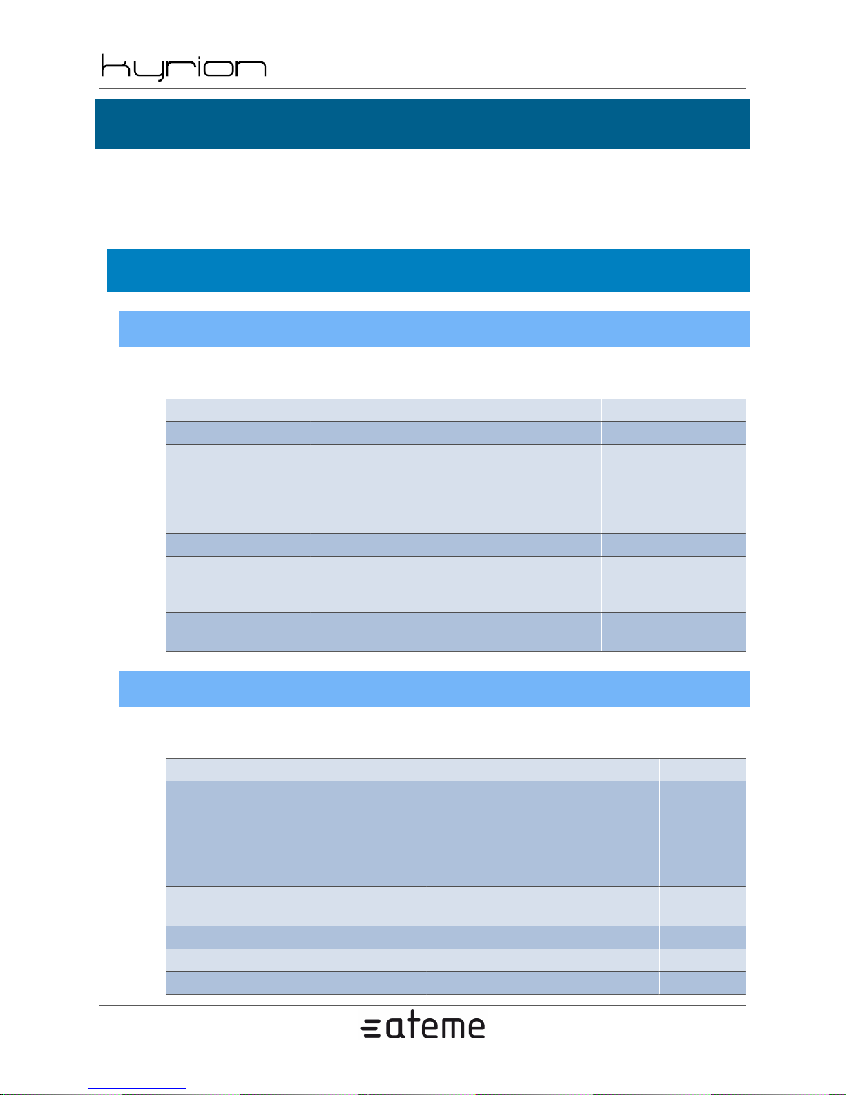
Table 5.1. Global
Parameter Value Note
Name (String) Preset name
Quality/latence
Output bitrate Bitrate of the output TS -
BISS mode
BISS Key (Hexadecimal number)
CM5000 users' manual UM-CM5000-FW1.1-REV1.0
2012-10-30
Custom
Best Quality
High Quality
Reduced Latency
Low Latency
Disabled
1
E
-
-
When BISS
mode is 1 or E
5.1.2. TS
Table 5.2. TS
Parameter Value Note
TS compliance
TS packet size
Null bitrate (number) -
PMT PID (number)
Program number (number) -
www.ateme.com Page 35
MPEG
DVB
ATSC
ISDB
SBTVD FullSeg
SBTVD OneSeg
188
204
-
-
Page 36
CM5000 users' manual UM-CM5000-FW1.1-REV1.0
PMT PCR PID (number) -
PAT TS ID (number) PAT period (number) -
PMT period (number) -
CAT period (number) -
Enabled non PSI tables - -
DVB/ISDB/SBTVD compliance
Those settings are available when 'TS conformance' is one of DVB, ISDB or SBTVD (Full/one-seg).
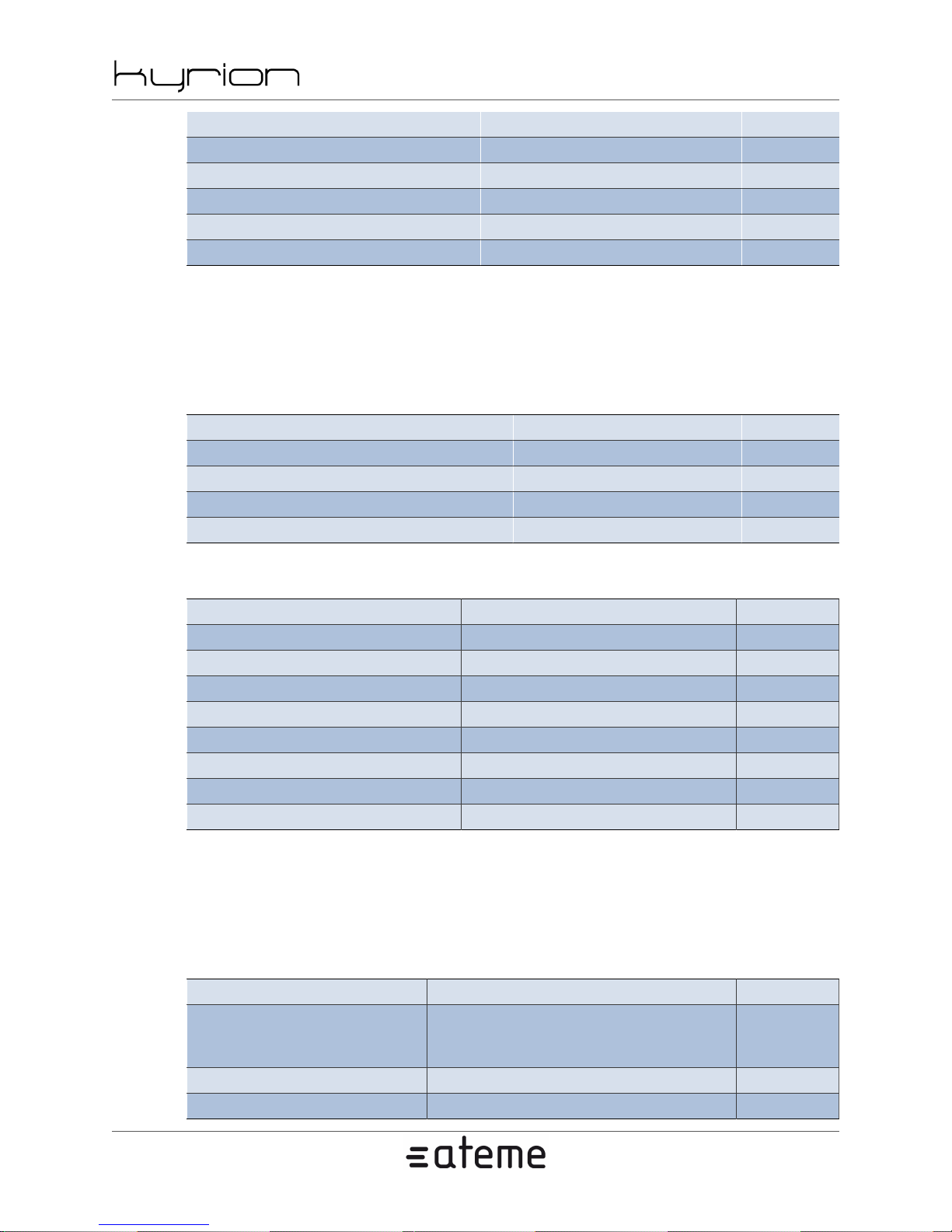
Table 5.3. DVB compliance
Parameter Value Note
Network ID (number) -
Network name (string) -
Service name (string) -
Service provider (string) -
2012-10-30
Table 5.4. Carrier ID
Parameter Value Note
Format 02 -
Manufacturer (string) -
Serial (string) -
Identifier (string) -
Telecine (string) -
Information (string) -
Longitude (real number) -
Latitude (real number) -
ATSC compliance
Those settings is available when 'TS conformance' is ATSC.
Table 5.5. ATSC
Parameter Value Note
Delivery
Channel short name (string) -
Channel major (number) -
None
Cable
Terrestrial
-
www.ateme.com Page 36
Page 37
CM5000 users' manual UM-CM5000-FW1.1-REV1.0
Channel minor (number) -
Modulation
5.1.3. Output ASI
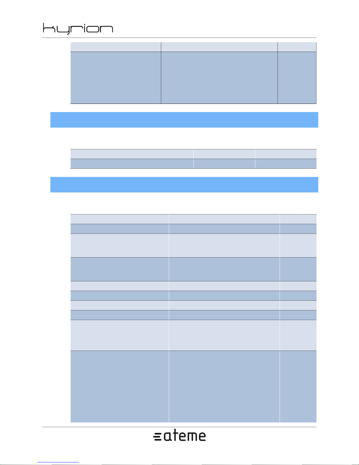
Table 5.6. Output ASI
Parameter Value Note
Enable - -
5.1.4. Output DVB-S/S2/DSNG
None
Analog
SCTE-1
SCTE-2
8VSB
16VSB
User
2012-10-30
-
Table 5.7. Output DVB-S/S2/DSNG
Parameter Value Note
Enable - -
Modulation state
Standard
Output power (real number) -
BUC's LOF (number) -
Frequency:(number) -
Symbol rate (real number) -
Modulation type
FEC
Modulated
Un-modulated
PRBS
DVB-S
DVB-S2
DVB-DSNG
QPSK
8PSK
16APSK
32APSK
1/4
1/3
2/5
1/2
3/5
2/3
3/4
4/5
5/6
7/8
-
-
-
-
www.ateme.com Page 37
Page 38
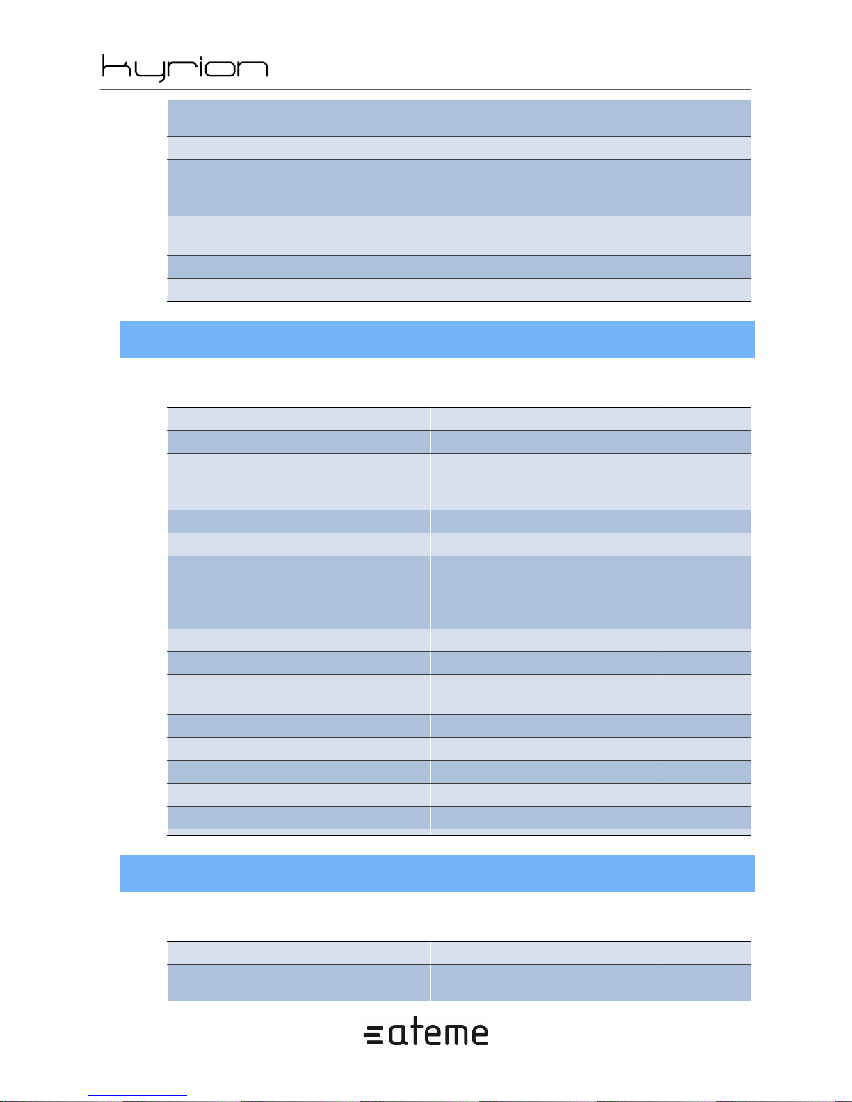
Use external reference clock - -
Roll-off
Frame type
Pilot mode - -
Spectral inversion - -
5.1.5. Output IP
Table 5.8. Output IP
Parameter Value Note
Enable - -
Main interface
Main IP (ip address) -
Main port (number) -
Backup interface
Backup IP (ip address) -
Backport port (number) -
Protocol
TS packet count (number) -
TTL (number) -
Spoofing enable - -
Spoofing address (ip address) -
Strip null packets - -
CM5000 users' manual UM-CM5000-FW1.1-REV1.0
2012-10-30
8/9
9/10
0.20
0.25
0.35
Normal
Short
MGT
Stream 1
Stream 2
None
MGT
Stream 1
Stream 2
UDP
RTP
-
-
-
-
-
5.1.6. Video
Table 5.9. Video
Parameter Value Note
Codec
www.ateme.com Page 38
MPEG-4 AVC
MPEG-4 AVC-I
-
Page 39
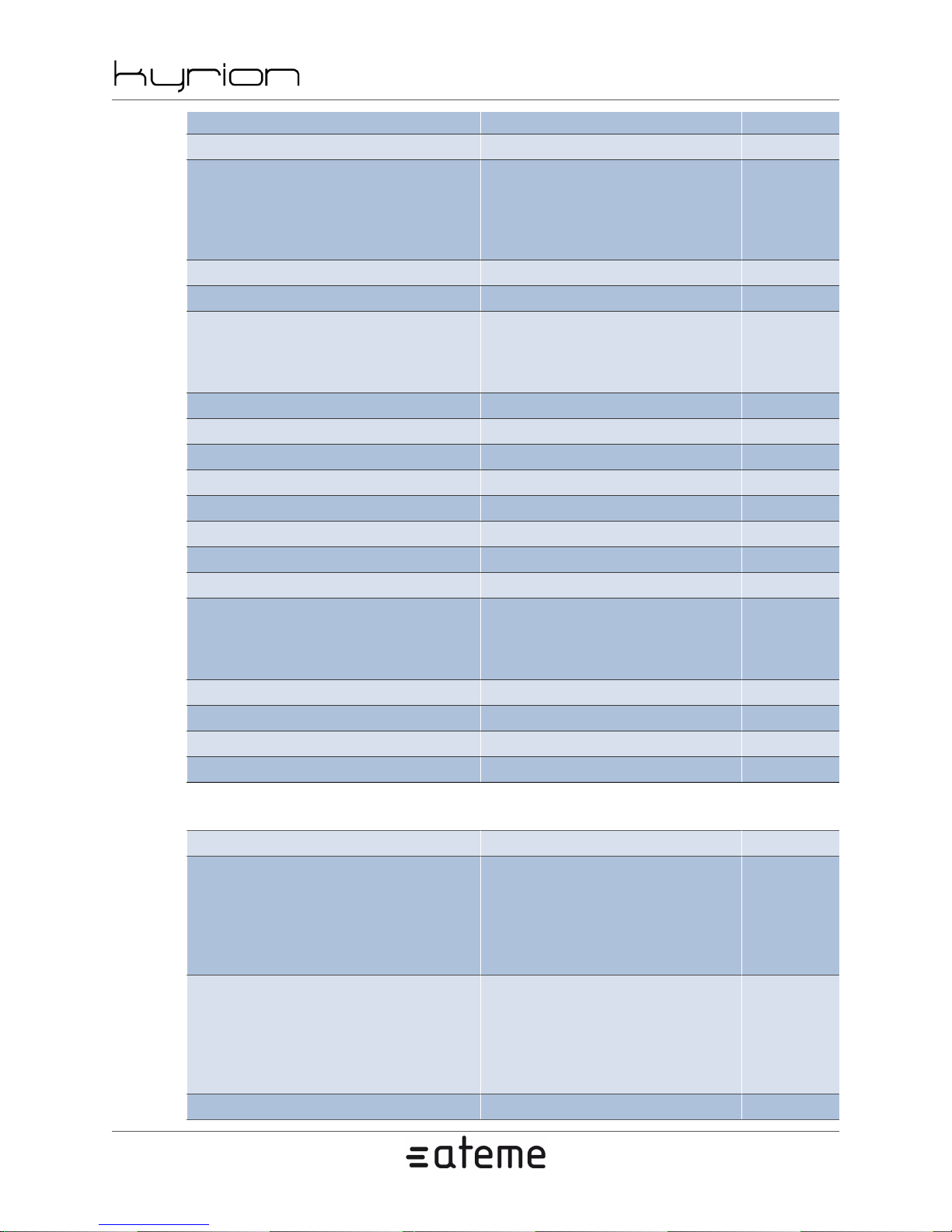
CM5000 users' manual UM-CM5000-FW1.1-REV1.0
2012-10-30
MPEG-2
Video PID (number) -
Black
Pattern
Emulation mode
Emulation moving pattern - -
Resize - -
Denoise
IVTC - -
Logo name (string) -
Logo X (number) Logo Y (number) -
GOP Size (number) -
GOP B Frames (number) -
GOP Closed - -
GOP Fixed - -
Aspect ratio
Enable CC - -
CPB Size (number) -
Disable adaptative GOP structures - -
Enable psychovisual enhancements - -
Freeze
Custom
Mute
None
Low
Medium
High
SDI (16:9 fallback)
SDI (4:3 fallback)
16:9
4:9
-
-
-
Table 5.10. MPEG-4 AVC
Parameter Value Note
Profile
Interlacing mode
Deblocking - -
www.ateme.com Page 39
Baseline
Main
High
High 10
High 4:2:2 8-bit
High 4:2:2 10-bit
Automatic
Frame
Field Only
PAFF
MBAFF
MBAFF and PAFF
-
-
Page 40
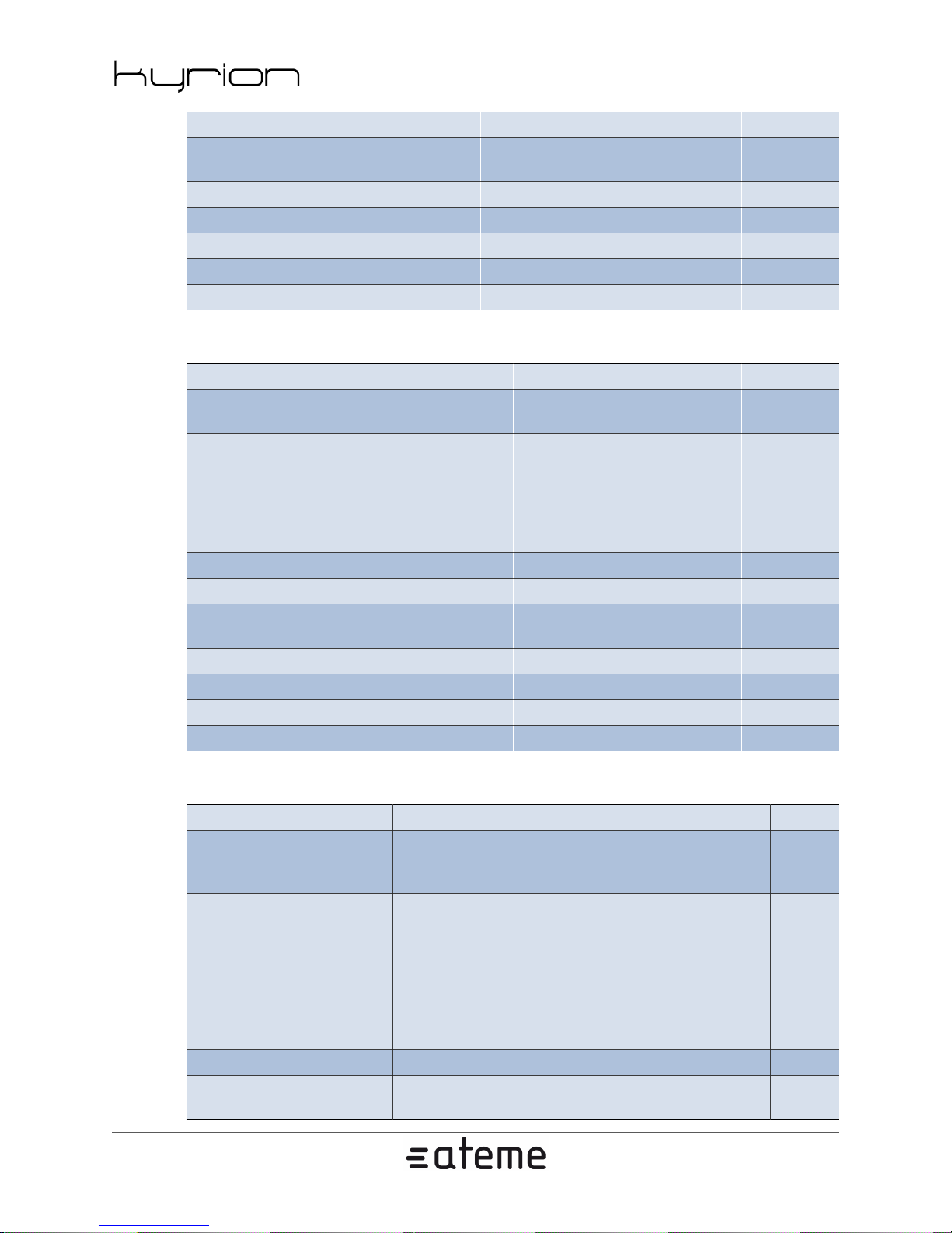
Deblocking strength (number) -
Scaling matrixes
Allow CABAC - -
Allow hierarchical B frames - -
Allow HRD information - -
Enable AFD bar data SEI - -
Enable picture timing SEI -
Table 5.11. MPEG-4 AVC-I
Parameter Value Note
Profile
Interlacing mode
Deblocking - -
Deblocking strength (number) -
Scaling matrixes
Allow CABAC - -
Allow HRD information - -
Enable AFD bar data SEI - -
Enable picture timing SEI -
CM5000 users' manual UM-CM5000-FW1.1-REV1.0
2012-10-30
Flat
Default
High 10 intra
High 4:2:2 intra
Automatic
Frame
Field Only
PAFF
MBAFF
MBAFF and PAFF
Flat
Default
-
-
-
-
Table 5.12. MPEG-2
Parameter Value Note
Profile
Interlacing mode
Allow dual prime -
Enable SMPTE-328M
time code
www.ateme.com Page 40
Main
High 4:2:2 (using 4:2:0)
High 4:2:2
Automatic
Frame
Field Only
MBAFF
Frame and Field
Frame and MBAFF
Field and MBAFF
Frame and Field and MBAFF
- -
-
-
Page 41
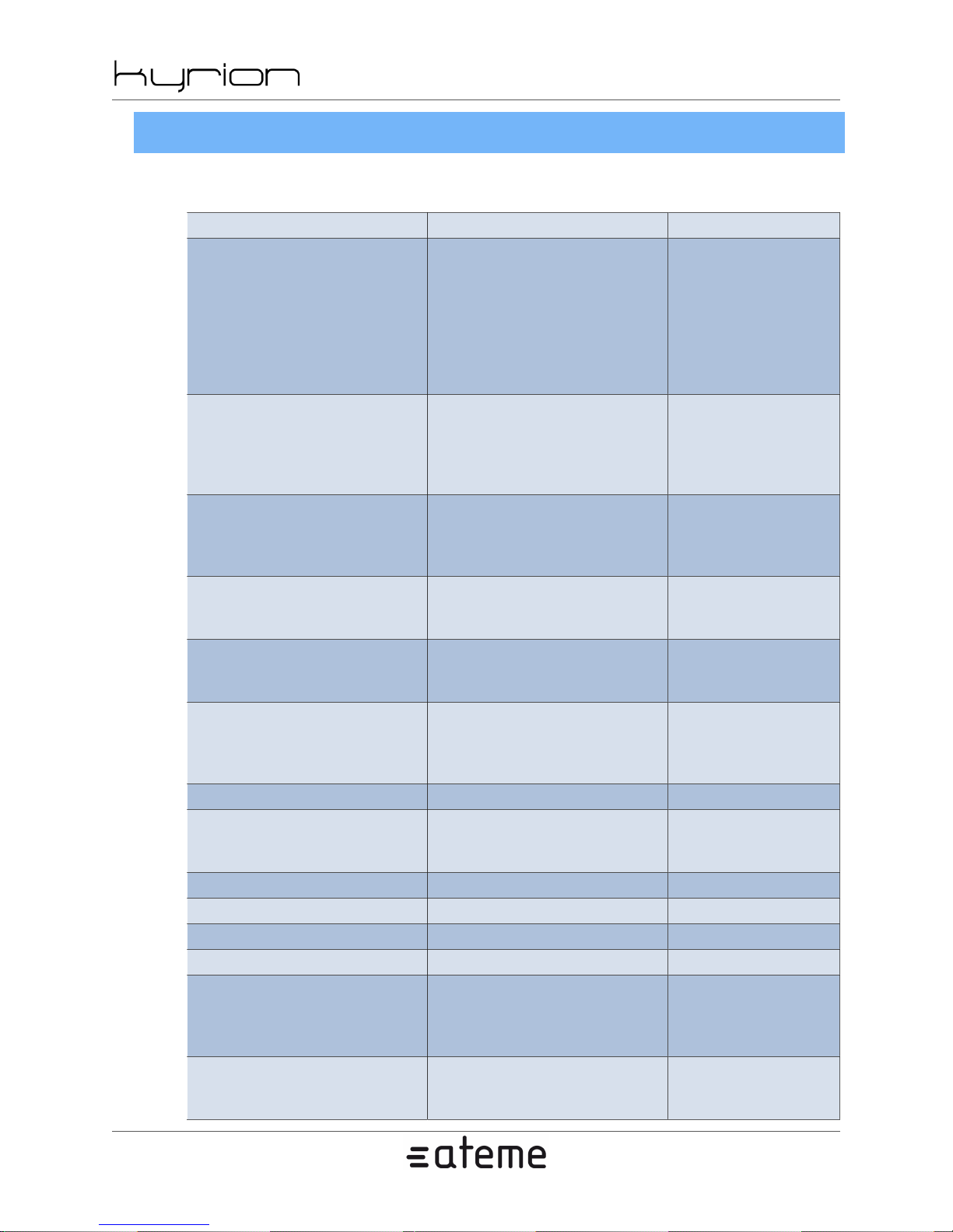
5.1.7. Audio
Table 5.13. Audio
Parameter Value Note
Codec
Non pass-through mode
Pass-through type
Dolby Digital (Plus)
pass-through bitrate
Dolby E/SMPTE-302M
pass-through size
SMPTE-302M pass-
through pair count
Bitrate (number) -
Input type
SDI mono/front/auxiliary/rear (group/pair) -
Analog mono/front/auxiliary/rear (XLR) -
AES mono/front/auxiliary/rear (XLR) -
Language code - -
Language type
Emulation mode
CM5000 users' manual UM-CM5000-FW1.1-REV1.0
2012-10-30
MPEG Layer2
AAC LC (MPEG-4)
AAC LC (MPEG-2)
AAC HEv1
AAC HEv2
Dolby Digital
Dolby Digital Plus
Pass-through
Mono
Dual-mono
Stereo
5.1
From Dolby E
Dolby Digital
Dolby Digital Plus
Dolby E
SMPTE-302M
(number)
16
20
24
1
2
3
4
SDI
Analog
AES
None
Clean effects
Hearing Impaired
Visual Impaired Commentary
Silence
Sine 440Hz
Noise
Only when pass-
through is not selected
Only when pass-
through is selected
Only when pass-
through Dolby Digi-
tal (Plus) is selected
Only when pass-
through Dolby E/
SMPTE-302M is selected
Only when pass-through
SMPTE-302M is selected
-
-
-
-
www.ateme.com Page 41
Page 42
Emulation forced - -
Delay (real number) -
Gain (real number) -
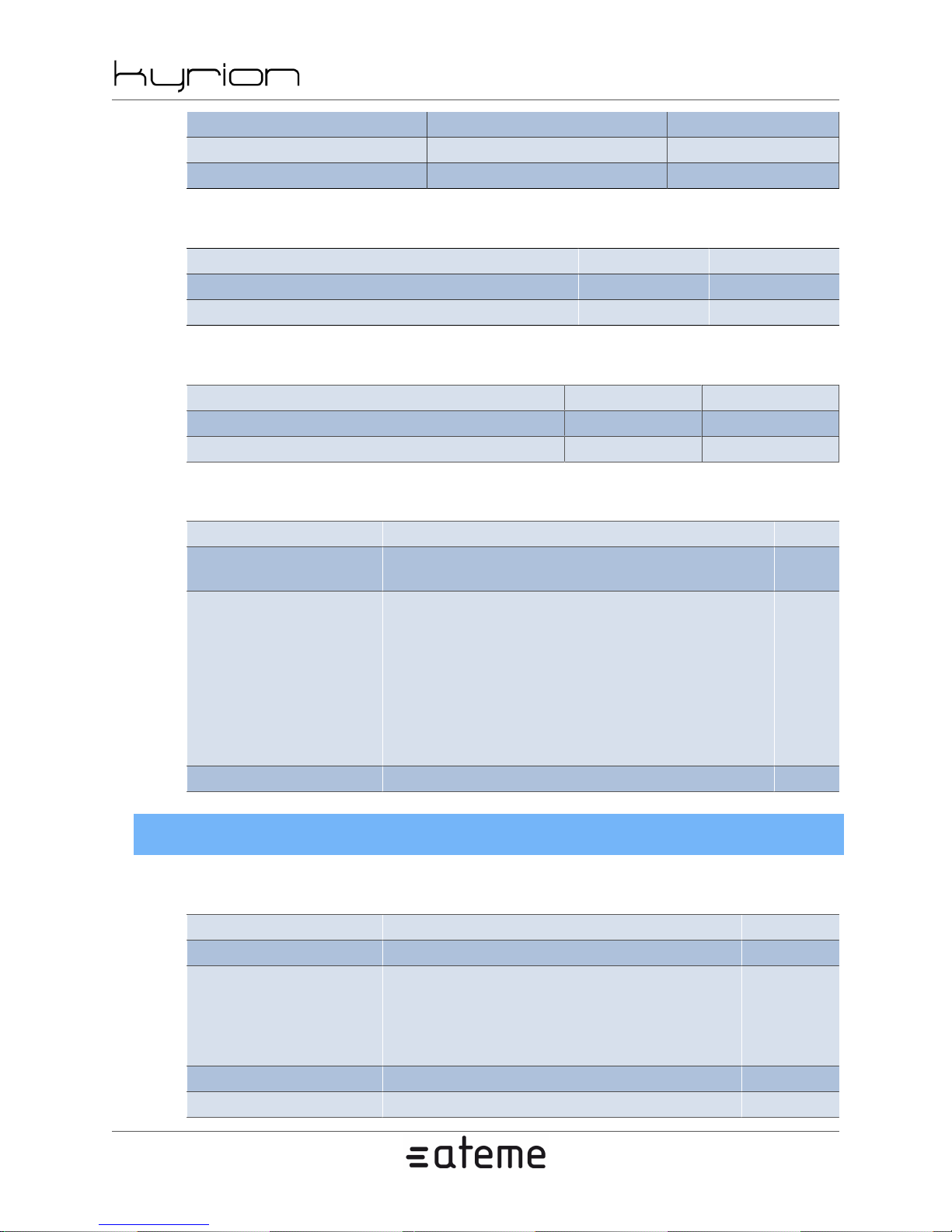
Table 5.14. MPEG Layer2
Parameter Value Note
Copyright bit - -
Original bit - -
Table 5.15. AAC
Parameter Value Note
TNS allowed - -
MS allowed - -
Table 5.16. Dolby Digital
CM5000 users' manual UM-CM5000-FW1.1-REV1.0
2012-10-30
Parameter Value Note
Metadata
Bitstream mode
Dialog normalization (real number) -
5.1.8. Data
Table 5.17. Data
Parameter Value Note
Enable - -
Type
Data PID (number) -
Delay (real number) -
User
Ancillary
Default
Complete
Music
Visually impaired
Hearing impaired
Dialogue
Commentary
Emergency
Karaoke
Teletext
VBI
SCTE-35
DVB Subtitles
SMPTE-2038
-
-
-
www.ateme.com Page 42
Page 43
CM5000 users' manual UM-CM5000-FW1.1-REV1.0
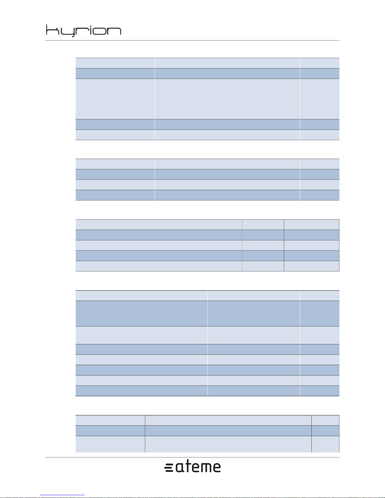
Table 5.18. Teletext and VBI teletext descriptor
Parameter Value Note
Enable - -
Initial
Subtitle
Description
Page (number) -
Language code - -
Additional Information
Program Schedule
Hearing Impaired
Table 5.19. Teletext and VBI teletext filter
Parameter Value Note
Enable - Field 1 (pass/dismiss per VBI line) Field 2 (pass/dismiss per VBI line) -
2012-10-30
-
Table 5.20. VBI
Parameter Value Note
Allow WSS - -
Allow VPS - -
Allow VITC - -
Allow Teletext - -
Table 5.21. DVB Subtitles
Parameter Value Note
TS source interface
TS source type
TS source address (ip address) -
TS source port (number) TS stream PID (number) -
TS stream PCR PID (number) -
TS stream maximum bitrate (number) -
MGT
Stream 1
Stream 2
Multicast
Unicast
-
-
Table 5.22. DVB Subtitles descriptor
Parameter Value Note
Enable - -
Type
www.ateme.com Page 43
Normal
Normal 4:3
-
Page 44
CM5000 users' manual UM-CM5000-FW1.1-REV1.0
Hearing Impaired 2.21:1
Language code - -
Composition ID (number) -
Ancillary ID (number) -
5.2. System Settings
5.2.1. System - Miscellaneous
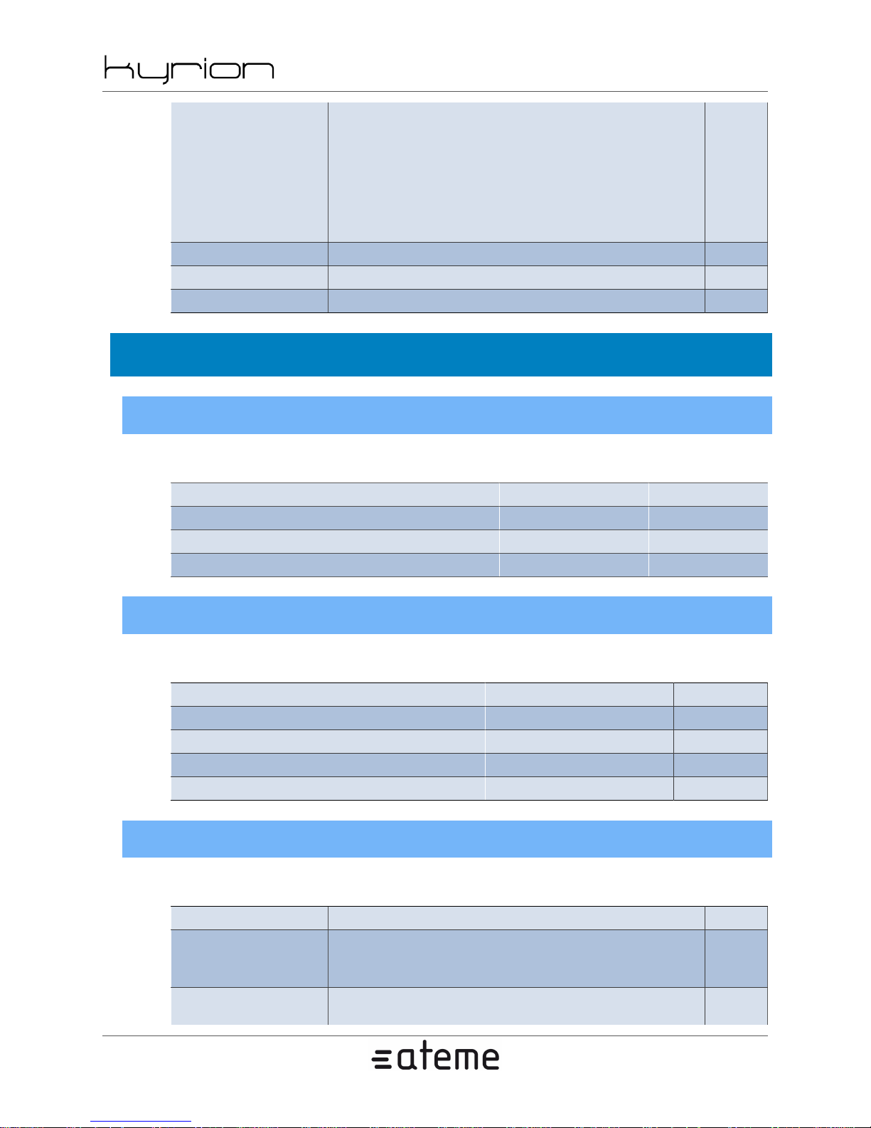
Table 5.23. Miscellaneous
2012-10-30
Normal 16:9
Normal 2.21:1
Normal HD
Hearing Impaired
Hearing Impaired 4:3
Hearing Impaired 16:9
Hearing Impaired HD
Parameter Value Note
System name (string) -
BISS injected ID - -
GUI password - -
5.2.2. System - Time
Table 5.24. Time
Parameter Value Note
System time (time) -
GMT offset (number) -
NTP server enable - -
NTP server address (ip address) -
5.2.3. System - Network Interface
Table 5.25. Interface
Parameter Value Note
Interface
Status
www.ateme.com Page 44
MGT
Stream 1
Stream 2
Disable
Static
-
-
Page 45
CM5000 users' manual UM-CM5000-FW1.1-REV1.0
Address (ip address) -
Subnet (netmask) -
10 Half Duplex
10 Full Duplex
Speed negotiation
100 Half Duplex
100 Full Duplex
1000 Half Duplex
1000 Full Duplex
5.2.4. System - Network VLAN
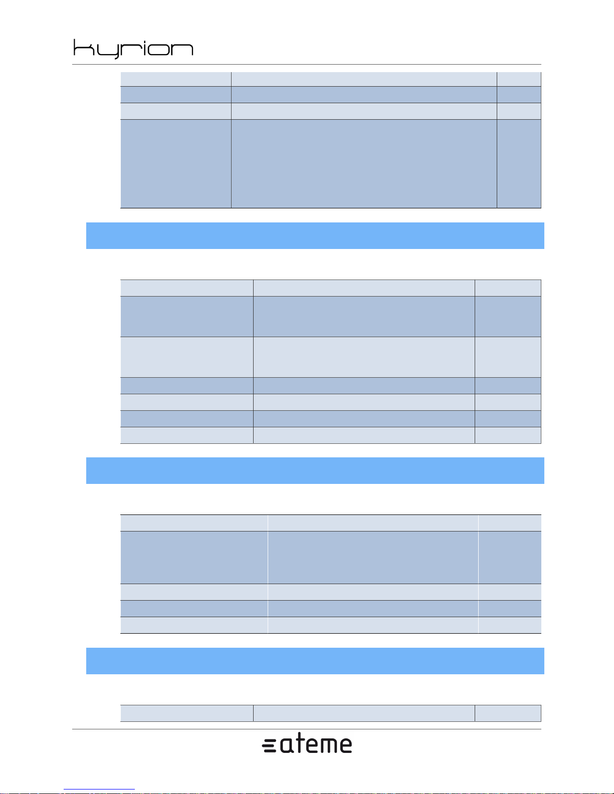
Table 5.26. VLAN
Parameter Value Note
Status
Interface
ID (number) -
Address (ip address) -
Subnet (netmask) -
Priority (number) -
DHCP
Auto
Disable
Static
DHCP
MGT
Stream 1
Stream 2
2012-10-30
-
-
-
5.2.5. System - Network Route
Table 5.27. Route
Parameter Value Note
Disable
Type
Destination (ip address) -
Netmask (netmask) Gateway (ip address) -
Default
Host
Net
-
5.2.6. System - Alarms
Table 5.28. Alarms
Parameter Value Note
www.ateme.com Page 45
Page 46
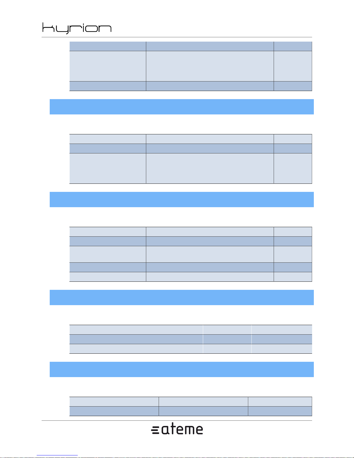
Identifiant - -
Level
Delay (number) -
5.2.7. System - Logs
Table 5.29. Logs
Parameter Value Note
Identifiant - -
Level
CM5000 users' manual UM-CM5000-FW1.1-REV1.0
2012-10-30
Disabled
Information
Warning
Critical
Disabled
Information
Warning
Critical
-
-
5.2.8. System - SNMP Trap Target
Table 5.30. Trap target
Parameter Value Note
Use - -
Type
Address (ip address) -
Port (number) -
SNMP v2 trap
SNMP v2 notification
5.2.9. System - SNMP Password
Table 5.31. Passwords
Parameter Value Note
Read only - -
Write only - -
-
5.2.10. System - Statmux
Table 5.32. Statmux
Parameter Value Note
Port (number) -
www.ateme.com Page 46
Page 47

CM5000 users' manual UM-CM5000-FW1.1-REV1.0
2012-10-30
www.ateme.com Page 47
Page 48
CM5000 users' manual UM-CM5000-FW1.1-REV1.0
6. Specific Operations
6.1. Installing License
On the web GUI, go to the System tab and click License.
The upper section is used to update the license settings.
To do so, click the Update button. A popup should appear asking for a license file. Click on the Browse
button to point to it and click Ok to proceed with the update, or Cancel to abort.
After a few seconds, a popup should appear, asking you to wait while the update process is running. Wait
until this popup disappears.
Note
License files are specific files provided by ATEME support. They should bear the extension
".lic" and are bound to a specific unit Serial Number. If the file does not meet these requirements, it will be rejected.
2012-10-30
The lower section is a summary of the licensed features with their status:
• 'Yes': A valid license file has been provided and the feature is available for use.
• 'No': The feature is disabled.
• 'Value': The feature is enabled and its limit is set to 'Value'
6.2. Firmware management
On the web GUI, go to the System tab and click Firmware.
This panel is dedicated to firmware management. From here, you can, install a new firmware version,
make a backup of your current version or restore your backup version.
It is always a good idea to make a backup of a known good functioning system version. It can be useful
to recover from situations requiring a Factory Reset per example or coming back from an update not fully
fulfilling your needs.
Firmware update
Click Update. A popup should appear asking for the update package file. Click on the Browse button to
point to it and click Ok to proceed with the update, or Cancel to abort.
After a few seconds, a popup should appear, asking you to wait while the update process is running. Wait
until this popup disappears.
www.ateme.com Page 48
Page 49
CM5000 users' manual UM-CM5000-FW1.1-REV1.0
Note
You can check that the upgrade process did well by checking that the displayed Current
Version number is the one expected.
Note
Update package are specific files provided by ATEME support. They should bear the extension ".pkg". Other files will be rejected.
Firmware backup
Click Backup, and press Yes in the popup asking you to confirm you really want to save your current
system version. The Backup button is disabled until the backup is done.
Note
2012-10-30
You can check that the backup process did well by checking that the Current Backup version
number matches the Current Version's one.
Firmware restore
Click Restore, and press Yes in the popup asking you to confirm you really want to restore the last saved
system version.
After a few seconds, a popup should appear, asking you to wait while the restore process is running. Wait
until this popup disappears.
Note
You can check that the restore process did well by checking that the System Version number
matches the Current Backup's one.
6.3. Recovery
If the web GUI becomes unreachable (and you are sure this is not a network problem) or the encoder
keeps rebooting by itself without allowing you to do anything, it may be due to a corrupted file or settings
incompatibility between 2 versions preventing the system to boot normally.
To recover from such situation, the encoder has a maintenance menu, accessible early on boot by the front
panel FP , and allowing cleaning some parts of the system.
Follow the steps below to access the maintenance menu:
• Step 1: Turn on your encoder or restart it if it's already on.
www.ateme.com Page 49
Page 50

CM5000 users' manual UM-CM5000-FW1.1-REV1.0
2012-10-30
• Step 2: Watch for a Maintenance message displayed on FP5 after a few seconds.
• Step 3: Quickly press the green ticker (FP7 see Section 4.2, “ Front Panel ”) to enter the Maintenance
menu.
Available options are:
• Continue: Exit the maintenance menu and continue booting normally.
• Reset Config: Erase all service configuration parameters.
The "Reset Config" function is useful when a newly installed version crashes on boot because of an incompatibility with the previous settings.
Only the service configuration parameters will be lost. The firmware version and system parameters will
stay the same.
This is the first thing to try.
• Backup System: Performs a backup of the current firmware version. Same function than Firmware
Backup described in Section 6.2, “ Firmware management ”.
• Restore System: Restores a previously saved system version.
If the current system version gets corrupted for some reason, restoring an older version can make the
system usable again allowing you to take control of the web interface back.
• Restore Factory: Restores the system to its factory version.
It will reset everything including: services configuration settings, firmware version and system parameters.
www.ateme.com Page 50
Page 51
CM5000 users' manual UM-CM5000-FW1.1-REV1.0
Appendix A. Appendix
A.1. Product's specification
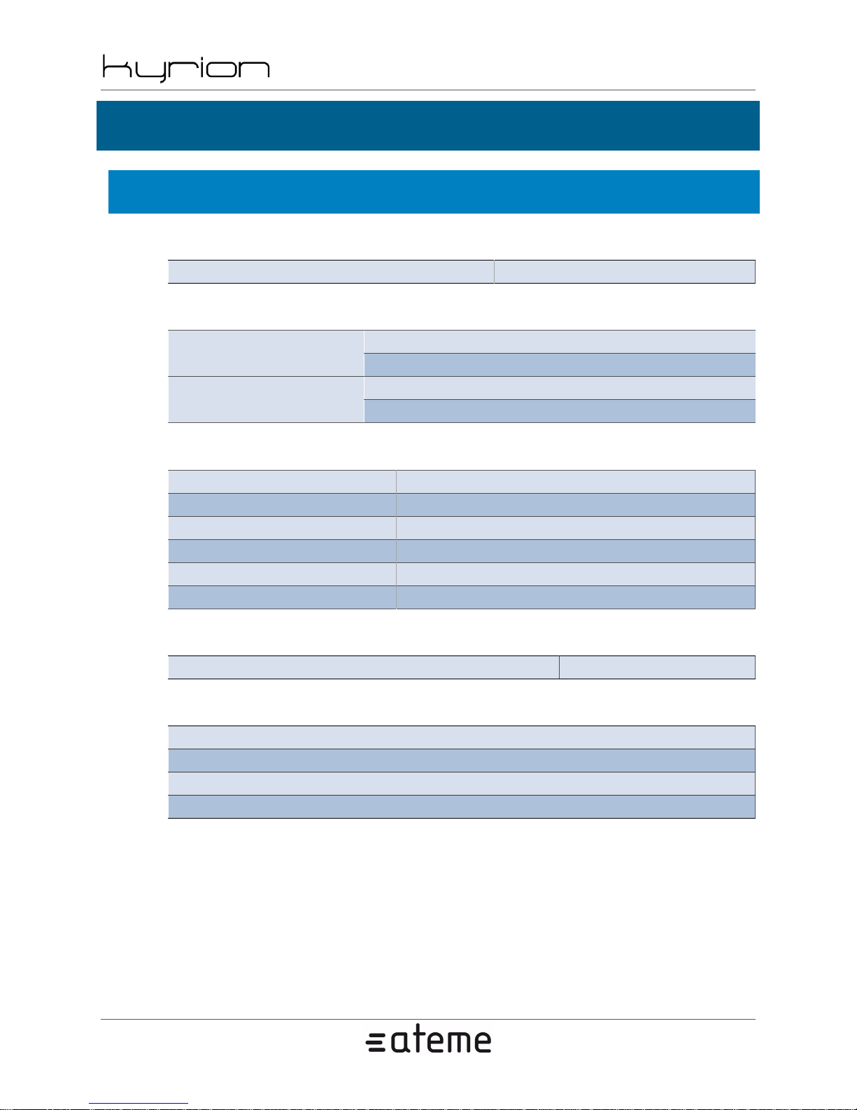
Table A.1. Specification - Identification
Product Name CM5000
Table A.2. Specification - Physical
2012-10-30
Dimensions
482x44x519 mm /19''x1.73''x 20,4''
Weight
19'' 1-RU
min: 6.4 kg/14.1 lbs
max: 7.3 kg/17 lbs
Table A.3. Specification - Environmental and Power
Cooling Cooling air flow from front to back
Operating Temperature 5 °C to 40 °C / +41 °F +104 °F
Storage Temperature -20 °C to 70 °C / -4 °F to +158 °F
Operating humidity 5 to 90% (non condensing)
Input Voltage Range 90-264VAC, 47-63Hz
Typical Consumption 90 W single channel
Table A.4. Specification - Certifications
Environmental ROHS
Table A.5. Specification - Configuration and Management
Full support of DataMiner Networks Management System
Full support of SNMP with remote SNMP supervisor
Embedded web-server configuration
Front panel with LCD/keypad
www.ateme.com Page 51
Page 52
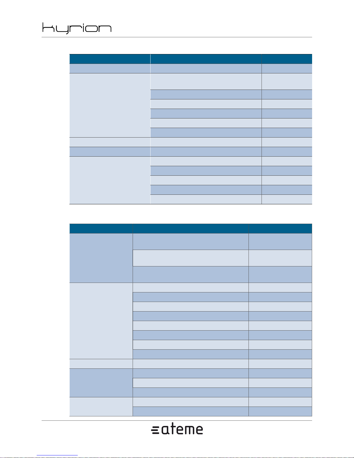
CM5000 users' manual UM-CM5000-FW1.1-REV1.0
Table A.6. Specification - Video Input
Function Values Requires
Input Number 1-2 SDI Inputs -
1080p 23.976/24/25/29.97/30/50/59.94/60 fps
Input Format
Probe Probe input -
Video Robustness Dynamical change of aspect ratio support -
Input Emulation
Last picture replay (Default mode) -
2012-10-30
HD1080p60
License
1080psf 23,97/24/25 fps HD License
1080i 25/29,97/30 fps HD License
720p 50/59,94/60 fps HD License
625i 25fps -
525i 29,97fps -
Black Pattern Disable -
Moving pattern -
Table A.7. Specification - Audio Input
Function Values Requires
SDI embedded (16 per SDI Input)
Source
Input Format
Selection Group/Pair -
Signaling
AES (8 AES pairs per audio
AES Extended Interface board)
Analog (4 analog pairs per audio
Analog Extended Interface board)
PCM stereo -
PCM dual mono -
Dolby Digital / Dolby Digital Plus Dolby E decoding license
AES3 (S320M)
Dolby E Pass Through -
Dolby E Decode -
White noise -Emulation
Sine 440Hz -
Language identifier -
Audio type description -
Max audio chan-
nel number License
The AES audio ex-
tended interface
The Analog audio
extended interface
PCM mono -
PCM 5.1 -
Silence -
www.ateme.com Page 52
Page 53
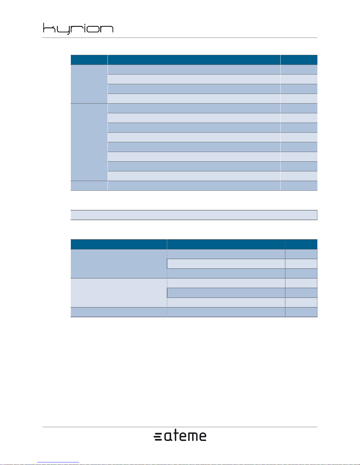
CM5000 users' manual UM-CM5000-FW1.1-REV1.0
Table A.8. Specification - Data Input
Function Values Requires
VITC (IEC-60461), WSS (ITU-R BT.1119-2) -
VPS (ETS 300 231-1998), WST (ITU-R BT.653-3) -
VBI
Close Caption (CEA/EIA-608-D) -
Teletext (ETSI EN 300 706) -
ATC (SMPTE 12M-2) -
AFD (SMPTE 2016M-1) -
VPI (SMPTE 352M) -
Close Caption - EIA 608 (SMPTE 334-2), EIA 708 (SMPTE 334-1) -
ANC
Teletext (OP47) -
VANC (SMPTE 2038) -
Teletext/VPS (SMPTE 2031M) -
SCTE104 (SMPTE 2010) -
Teletext Page properties configuration -
2012-10-30
Table A.9. Specification - Black Burst-3Level and ASI Synchronization
Black Burst/3Level and ASI Synchronization are not supported on CM5000
Table A.10. Specification - Filter
Function Values Requires
Resize 4/5 3/4 2/3 1/2 -
Resize CIF/SIF - QCIF - SQCIF -Video filtering
Denoiser (Low, Medium, High) -
Resampling 48kHz -
Gain (+/- 30dB) -Audio filtering
Delay (+/- 500ms) -
Teletext filtering Field line selection -
www.ateme.com Page 53
Page 54
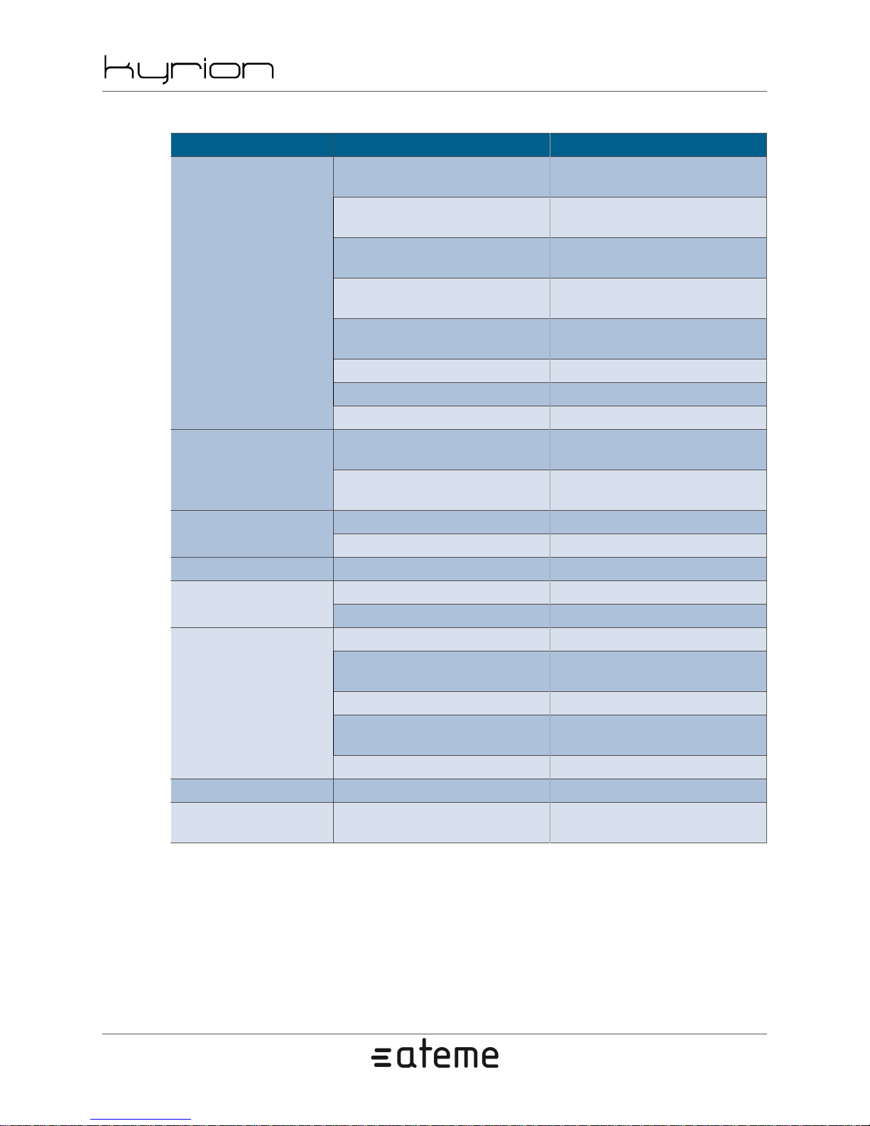
CM5000 users' manual UM-CM5000-FW1.1-REV1.0
Table A.11. Specification - Specification - Video Processing
Function Values Requires
Baseline (420 8 bits)
Main - High 420 8 bits
High 420 10 bits
Profile MPEG-4 AVC
Reduced and Low Latency Mode -
Profile MPEG-4 AVC-I
Profile MPEG2
Core Generation Generation 4 -
Rate Control
Bitrate
GOP 0-255 -
Preset
High 422 8 bits - Up to 100 Mbps MPEG-2 video encoding License
MPEG-4 AVC : up to 120 Mbps
MPEG-4 AVC-I : up to 160 Mbps -
SD/HD 0,5k-100Mbs MPEG-2 MPEG-2 video encoding License
Custom, High Quality,Reduced
High 422 8 bits
High 422 10 bits
MBAFF + Field Mode -
CABAC/CAVLC selection -
High 10 Intra 8/10 bits
High 422 Intra 8/10
bits - Up to 160 Mbps
Main - High 420 8 bits MPEG-2 video encoding License
CBR -
Capped VBR -
MPEG-2 : up to 100 Mbps -
SD/HD 0,5k-150Mbs
MPEG-4 AVCI
Latency, Low latency
MPEG-4 AVC video and
MPEG-4 AVC and 4:2:2 and
10-bit encoding Licenses
2012-10-30
MPEG-4 AVC video
encoding License
MPEG-4 AVC video
encoding License
10 bit encoding Licenses
MPEG-4 AVC and High
4:2:2 encoding Licenses
MPEG-4 AVC-I video
encoding License
MPEG-4 AVC-I video
encoding License
MPEG-4 AVC max-
imum bitrate License
MPEG-4 AVC-I video
encoding License
-
www.ateme.com Page 54
Page 55
CM5000 users' manual UM-CM5000-FW1.1-REV1.0
2012-10-30
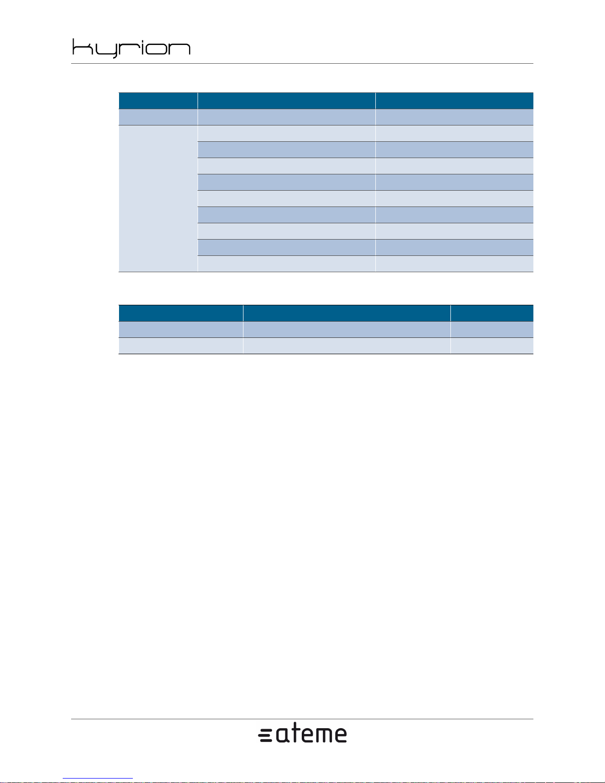
Table A.12. Specification - Audio Processing
Function Values Requires
Number of track Up to 16 per channel Max audio channel number License
MPEG1-LII [32-384kbs] Default CODEC
MPEG2-AAC-LC [16-512kbps] AAC LC/HE encoding License
MPEG4-AAC-LC [16-512kbps] AAC LC/HE encoding License
MPEG4-AAC-HE [16-64kbps] AAC LC/HE encoding License
Encoder
MPEG4-AAC-HEv2 [16-64kbps] AAC HEv2 encoding License
Dolby E pass-through -
Dolby Digital / Digital+ pass-through -
Dolby E decoding to DD/DD+ Dolby E decoding License
Dolby DD / DD+ encoding Dolby E decoding License
Table A.13. Specification - Specification - Data Processing
Function Values Requires
DVB Subtitle EN 300-743 -
SCTE35 SCTE104 (VANC/SDI) to SCTE35 (TS) -
www.ateme.com Page 55
Page 56
CM5000 users' manual UM-CM5000-FW1.1-REV1.0
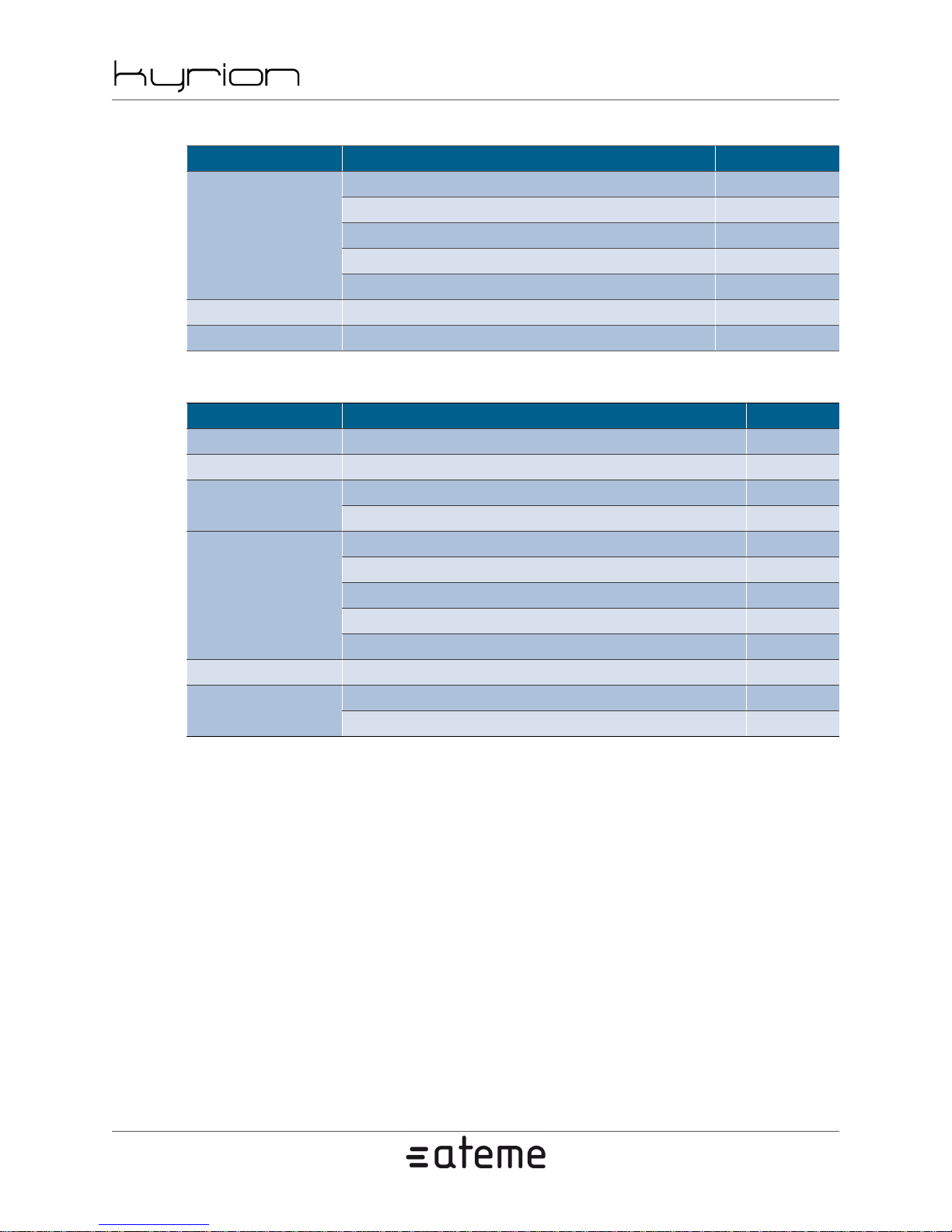
Table A.14. Specification - Muxer
Function Values Requires
Output mode CBR, VBR -
Packet size 188/204 -
MPEG2-TS
BISS BISS 1/E Support BISS License
Conformance MPEG, DVB, ATSC, ISDB, SBTVD - Full Seg -
PID setting for Video, Audio, Data -
Video bitrate constrained by TS bitrate -
Dynamical change of TS PID -
Table A.15. Specification - Output
Function Values Requires
ASI 4 Outputs (2 per channel if dual) - except modulator option SDI 1 SDI loopback - except modulator option -
IP Interfaces
Network
Flexibility Dynamical change of output configuration -
Protocol
FEC (SMPTE 2022) - 1D and 2D support FEC License
1 MGT interface -
2 Stream interfaces -
Backup stream -
Multi-network (4 target stream) -
VLAN TAG -
Route Table Editor -
Source address Spoofing -
UDP, RTP -
2012-10-30
www.ateme.com Page 56
Page 57
CM5000 users' manual UM-CM5000-FW1.1-REV1.0
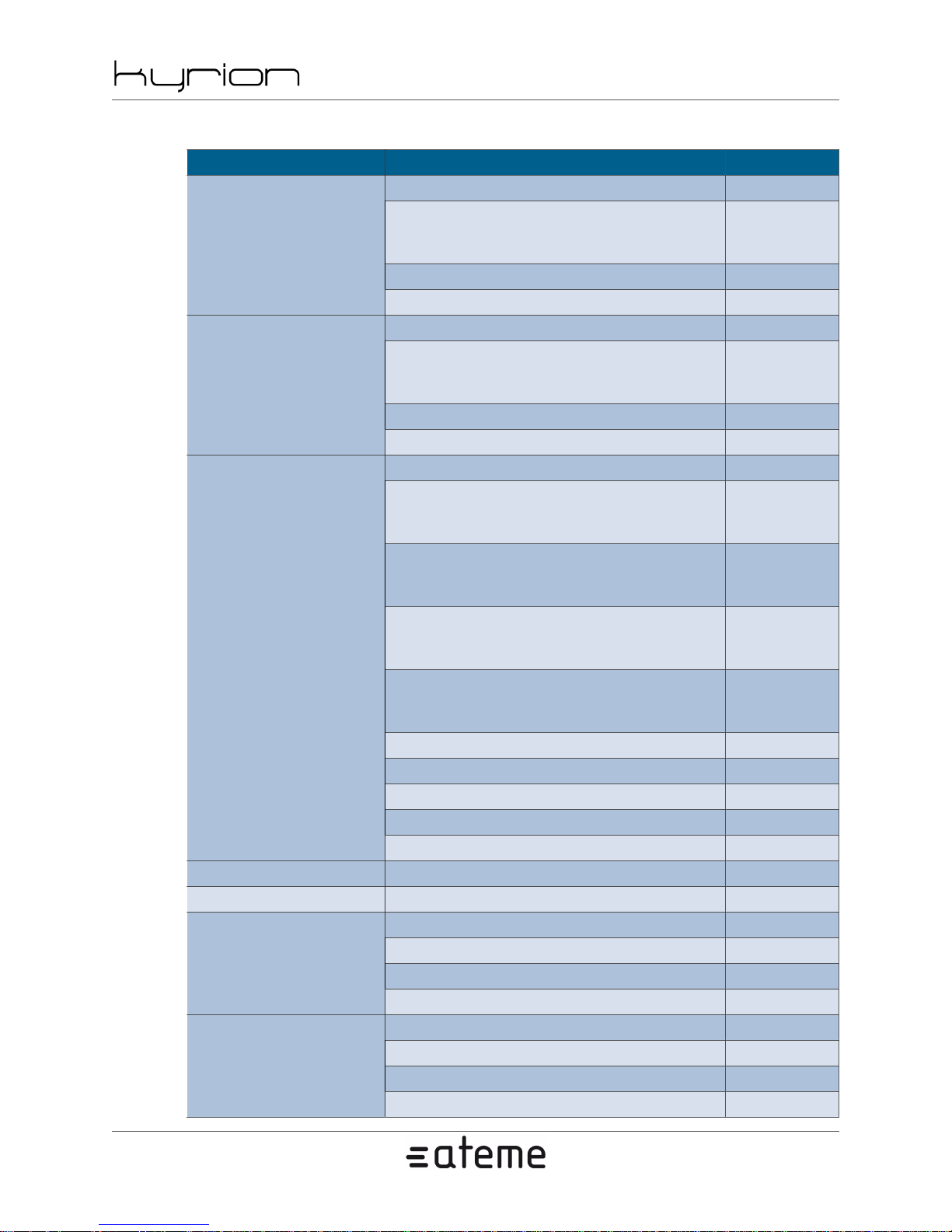
Table A.16. Specification - L-Band or IF Modulator
Function Values Requires
Constellation QPSK -
FEC QPSK 1/2, 2/3, 3/4, 5/6, 7/8
DVB-S (EN 300 421)
Roll-off 0.35 -
Bitrate from 3 Mbps to 40 Mbps -
Constellation 8PSK -
FEC 8PSK 2/3, 5/6, 8/9
DVB-DSNG(EN 300 10)
Roll-off 0.35 -
Bitrate from 3 Mbps to 40 Mbps -
Constellation QPSK, 8PSK, 16APSK, 32APSK -
FEC QPSK 1/4, 1/3, 2/5, 1/2,
3/5, 2/3, 3/4, 4/5, 5/6, 8/9, 9/10
FEC 8PSK 3/5, 2/3, 3/4, 5/6, 8/9, 9/10
FEC 16APSK 2/3, 3/4, 4/5, 5/6, 8/9, 9/10
DVB-S2 (EN 302 307)
FEC 32APSK 3/4, 4/5, 5/6, 8/9, 9/10
Roll-off 0.20, 0.25, 0.35 -
Short Frames, Long Frames -
Pilot Mode On/Off -
Modulation CCM -
Bitrate from 3 Mbps to 40 Mbps -
Bandwidth 1 to 60MHz (Symbol Rate up to 45 MBd) -
RF Output mode Modulated / Single boosted sine tone / PRBS mode
L-Band [950-2150MHz] (Extended L-Band) -
IF [50-180MHz] (Extended IF) -
Frequency
Step size 100 Hz Accuracy 0.2 Hz -
Range from 0 dBm to -20 dBm +/-1 dB -
Step size 0.1 dB -
Level
Stability +/- 0.1 dB / 10°C -
Return loss more than 12 dB -
2012-10-30
DVB-S QPSK
Modula-
tion License
DVB-DSNG
8PSK Modu-
lation License
DVB-S2
QPSK Modulation License
DVB-S2
8PSK Modu-
lation License
DVB-S2
16APSK Modu-
lation License
DVB-S2
32APSK Modu-
lation License
www.ateme.com Page 57
Page 58
CM5000 users' manual UM-CM5000-FW1.1-REV1.0
2012-10-30
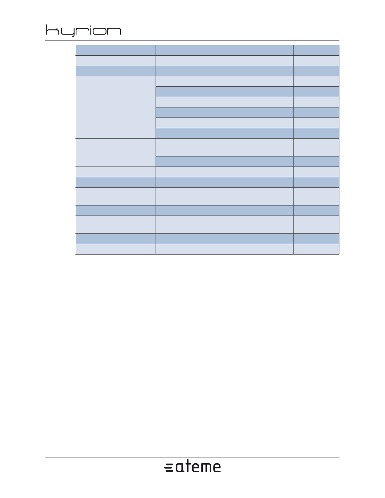
SNR > 34 dB -
Shoulder rejection Less than -45 dB at f/fn = 2 -
H2 rejection Less than -45 Db -
@10Hz less than -55 dBc/Hz -
@100Hz less than -70 dBc/Hz -
@1KHz less than -80 dBc/Hz -
Phase Noise
@10KHz less than -90 dBc/Hz -
@100KHz less than -100 dBc/Hz -
@1MHz less than -120 dBc/Hz -
Less than -65 dBc from 950 to 2100
Spurious
MHz except -60 dBc for the 1600 MHz
Less than -60 dBc for the rest -
Spectrum Reverse Configurable -
RF Monitoring Output RF Output level - 20dB -
Reference Clock
External reference clock in-
put or internal reference clock
Internal Reference Clock 10 MHz +/-3ppm -
External Refer-
ence Clock Input
10 MHz (-15 dBm / 15 dBm) -
Reference Clock Output 0 dBm +/- 3 dB -
ASI Output Available for monitoring -
-
-
www.ateme.com Page 58
Page 59
CM5000 users' manual UM-CM5000-FW1.1-REV1.0
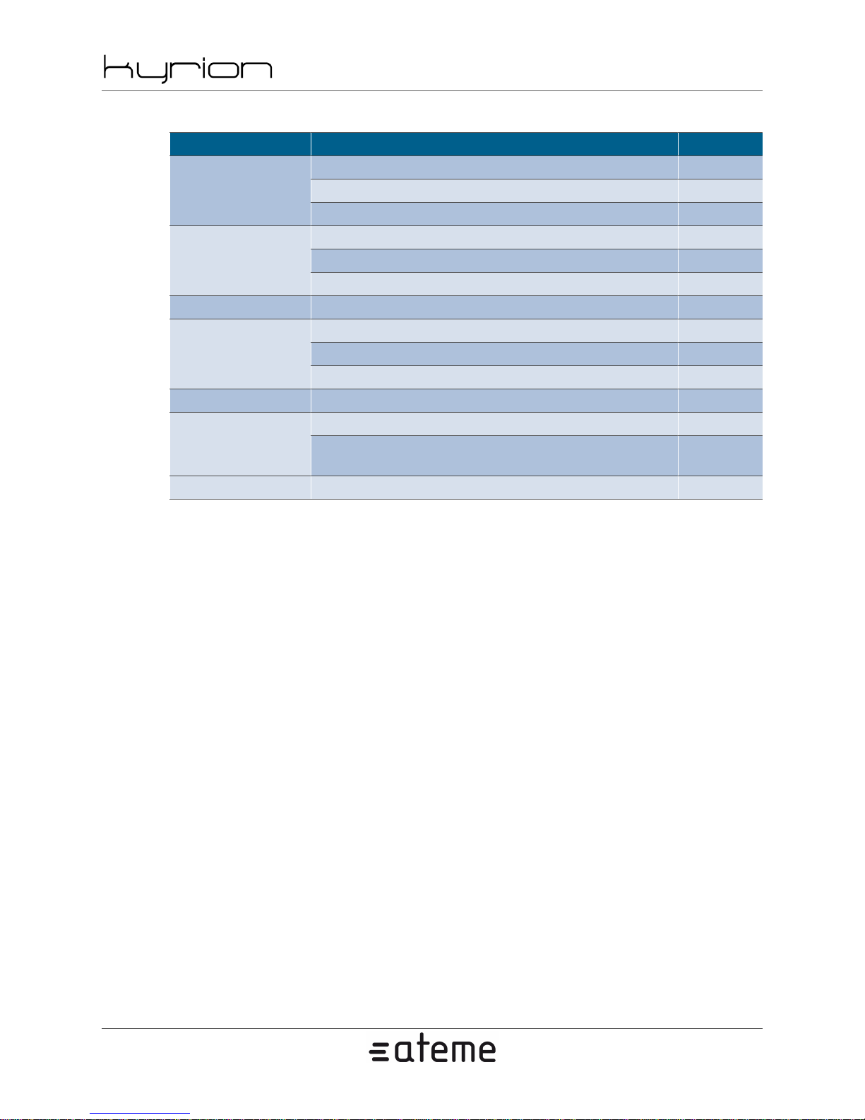
Table A.17. Specification - System
Function Values Requires
NTP server support (high precision option) -Time
Password SNMP R and RW, WebGui -
Backup firmware save and restore -Firmware
MIB MIB package (including changelog) is embedded -
Configuration
GPIO 2 Inputs and 2 Outputs -
Backward and partially forward compatibility of the encoder configuration
2012-10-30
Time update -
GMT offset support -
Individual trap support -
SNMP trap support -Alarms
Alarm message time filtering -
Firmware update -
License update -
Export and Import 128 files -
-
www.ateme.com Page 59
Page 60

Feature Licenses
Some features need a license to be activated:
• AAC LC/HE support
• AAC HEv2 support
• Pro-MPEG FEC support
• HD video support
• MPEG-4 AVC High 4:2:2 profile support
• Max audio channel number support
• Dolby AC3/EAC3 encoding support
• Dolby E decoding support
• MPEG-2 video encoding support
CM5000 users' manual UM-CM5000-FW1.1-REV1.0
2012-10-30
• MPEG-4 AVC video encoding support
• DVB Subtitles pass-through support
• BISS support
• MPEG-4 AVC-I video encoding support
• MPEG-4 AVC 10-bit support
• MPEG-4 AVC maximum bitrate
• DVB-S-QPSK Modulation Support
• DVB-DSNG-8PSK Modulation Support
• DVB-S2-QPSK Modulation Support
• DVB-S2-8PSK Modulation Support
• DVB-S2-16APSK Modulation Support
• DVB-S2-32APSK Modulation Support
• 1080P60 video support
www.ateme.com Page 60
Page 61

A.2. Warranty
ATEME warrants your Kyrion(R) against any defect in material and workmanship, under normal use, for
the period designated on your warranty certificate. In the event this product is found to be defective within
the warranty period, ATEME may, at its will, repair or replace the defective Kyrion(R).
This warranty is void if:
• The Kyrion(R) was operated/stored in abnormal use or maintenance conditions;
• The Kyrion(R) is repaired, modified or altered, unless such repair, modification or alteration is expressly
authorized in writing by ATEME;
• The Kyrion(R) was subjected to abuse, neglect, lightning strike, electrical fault, improper packaging
or accident;
• The Kyrion(R) was installed improperly;
• The Serial Number of the Kyrion(R) is defaced or missing;
• The broken part is a non ATEME approved replacement part;
CM5000 users' manual UM-CM5000-FW1.1-REV1.0
2012-10-30
• The tamper seal on the Kyrion(R) casing is broken.
ATEME and its suppliers accept no liability for any loss of service during the use of this device, or for
any of the problems caused as a result.
ATEME will not, under any circumstances, be liable to direct, uncommon or consequential damages such
as, but not limited to, damage or loss of property or equipment, loss of profits or revenues, cost of replacement goods, or expense or inconvenience caused by service interruptions.
Any loss, corruption or destruction of data while using an ATEME Kyrion(R) is the sole responsibility of
the user, and under no circumstances will ATEME be held liable for the recovery or restoration of this data.
Under no circumstances will any person be entitled to any sum greater than the purchase price paid for
the Kyrion(R).
To obtain warranty service, call ATEME Technical Support. You will be asked to provide your ATEME
product's Serial Number, and you may be asked to furnish proof of purchase to confirm that the Kyrion(R)
is still under warranty.
All Kyrion(R) returned to ATEME must be securely packaged in their original box and shipped with
postage prepaid.
www.ateme.com Page 61
Page 62
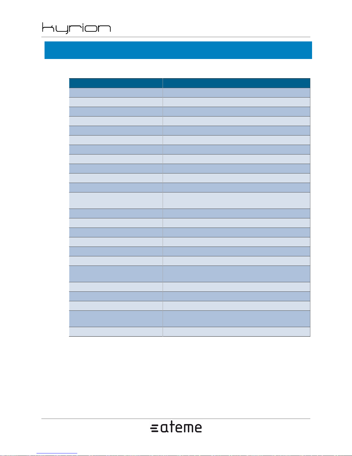
CM5000 users' manual UM-CM5000-FW1.1-REV1.0
A.3. Normative Reference
Table A.18. Normative reference
Subject Reference
Ancillary AFDBarData SMPTE 2016M-1/3
Ancillary ATC SMPTE 12M-2
Ancillary Audio HD SMPTE 299M
Ancillary Audio SD SMPTE 272M
Ancillary cc608 SMPTE 334-2
Ancillary cc708 SMPTE 334-1
Ancillary DvbScte SMPTE 2031M
Ancillary SCTE-104 SMPTE 2010
Ancillary Video Payload Identification SMPTE 352M
BISS Tech 3290 (EBU)
MPEG-2 TS ISO/IEC 13818-1
MPEG-2 TS PID Teletext
MPEG-2 TS PID VBI ETSI EN 301 775 (DVB, ISDB, SBTVD)
MPEG-2 Video ISO/IEC 13818-2
MPEG-2 Video time code User Data SMPTE 328M
MPEG-2 Video/MPEG-4 AVC AFD ETSI TS 101 154 (Annexe B) / A/53 part 4
MPEG-2 Video/MPEG-4 AVC CC ETSI TS 101 154 (Annexe B) / A/53 part 4
MPEG-4 AVC ISO/IEC 14496-10
Teletext
VBI cc608 CEA/EIA-608-D (625i/525i)
VBI VITC IEC-60461 (625i/525i)
VBI VPS ETS 300 231-1998 (625i)
VBI WSS
VBI WST ITU-R BT.653-3 (625i)
ETSI EN 300 472 (DVB, ISDB, SBTVD) -
Specifications for embedding teletext into TS
ETSI EN 300 706 (DVB, ISDB, SBTVD)
ITU-R BT.1119-2 and ETSI EN 300 294
(625i) / IEC 61880 Ed. 1.0 b:1998 (525i)
2012-10-30
- Specifications of the teletext syntax
www.ateme.com Page 62
Page 63
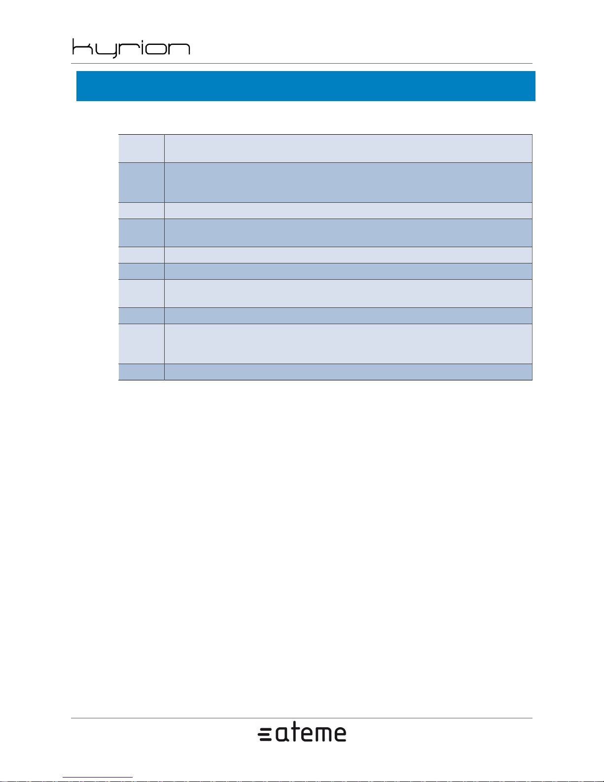
A.4. Glossary
Table A.19. Glossary
CM5000 users' manual UM-CM5000-FW1.1-REV1.0
2012-10-30
3:2 pulldown
422/420
ASI Asynchronous Serial Interface
BISS
CABAC Context-based Adaptive Binary Arithmetic Coding
CAVLC Context Adaptive Variable Length Coding
Chromi-
nance
EBU European Broadcasting Union
FEC
FTP File Transfer Protocol. Protocol used to transfer files over a TCP/IP network.
Process of converting 24 frame/s material to 29.97 frame/s.
Sampling method. In 420 sampling, chrominance components have half the horizontal and
vertical resolution of luminance component. In 422 sampling, chrominance components
have half the horizontal resolution of luminance component
Basic Interoperable Scrambling System. Non-proprietary encryption from EBU
(Tech3290).
Color difference component
Forward Error Correction. System of error control for data transmission where the sender
adds redundant data (error-correcting code) to its messages. The receiver can check the accuracy of the transmission and eventually correct errors.
www.ateme.com Page 63
Page 64

CM5000 users' manual UM-CM5000-FW1.1-REV1.0
A.5. Support and Ressources
Contact Technical Support
Before You Contact Technical Support:
• Read the manuals.
• Try to isolate the problem or to reproduce it many times.
• Make sure that all of the cables are correctly and firmly attached.
If you have asked yourself all of the pertinent questions in the troubleshooting checklist, and you still can't
get your Kyrion(R)to work properly, contact us via the provided link.
ATEME Technical Support - [email protected]
Before contacting us, make sure that you have a physical access to your Kyrion and that you have the
following information on hand:
2012-10-30
• Your Kyrion's Serial Number
• Names of any other devices installed in your system (Router's brands, specific equipments, ...)
Online Resources
Visit this link for more information and documentation about ATEME and ATEME products.
http://www.ateme.com/
Customer Service
ATEME Customer Service provides assistance with product information, sales, registration, and other
non-technical issues.
To find out how to contact ATEME Customer Service, please visit http://www.ateme.com/ for your region
or country and click Contact Us.
www.ateme.com Page 64
 Loading...