

1
PEGASUS-02 P / SKAT-02 P
PEGASUS-02 M / SKAT-02 M
MITER SAWS
OPERATING AND SAFETY INSTRUCTIONS
Operating and Safety Instructions

2
CONTENTS Page
1. General Information 3
1.1. Introduction 3
1.2. Manufacturer 3
2. Machine’s description and purpose of use 3
2.1. Machine’s description 3
2.2. Technical features 5
2.3. Cutting diagram 6
2.4. Overall dimensions 7
2.5. Part lists and technical drawings 8
3. Safety 10
3.1. Safety information 10
3.2. Accident prevention 10
3.3. General safety information 11
4. Transport of the machine 12
5. Installation of your machine 13
5.1. Preparation 13
5.2. Electric connection 14
6. Machine safety information 15
7. Operation 16
7.1. Air pressure adjustment of pneumatic clamps 16
7.2. Miter cut 18
8. Safe installation of the saw blade 19
9. Maintenance 20
9.1. Periodic checks 20
9.2. Maintenance at the end of working day 21
10. Troubleshooting Guide 21
11. Electric / Pneumatic Components 22
11.1 Electric components 22
11.2 Pneumatic components 22
Operating and Safety Instructions

3
1. GENERAL INFORMATION
1.1. INTRODUCTION
The user’s manual given by the manufacturer contains necessary information about the
machine parts. Each machine operator should read these instructions carefully, and the
machine should be operated after fully understanding them.
Safe and efficient use of the machine for long term depends on understanding and
following the instructions contained in this manual. The technical drawings and details
contained in this manual constitute a guide for the operator.
1.2. DISTRIBUTOR
ATech Machine, Inc.
429 E. Diamond Ave. #F – Gaithersburg, MD 20877 USA
Phone: +1-301-556-9789 Toll Free: 1-866-80A-TECH Fax: +1-301-542-0140
Website: www.atechna.com E-mail: info@atechna.com
In case of any technical problem please contact your nearest ATECH dealer, or ATECH
head office through the above mentioned phone fax or e-mail address.
Technical labels with the model description of the machine are fixed onto the front side
of each machine.
The machine’s serial number and manufacturing year are stipulated on the technical
label.
2. MACHINE’S DESCRIPTION AND PURPOSE OF USE
2.1. MACHINE’S DESCRIPTION
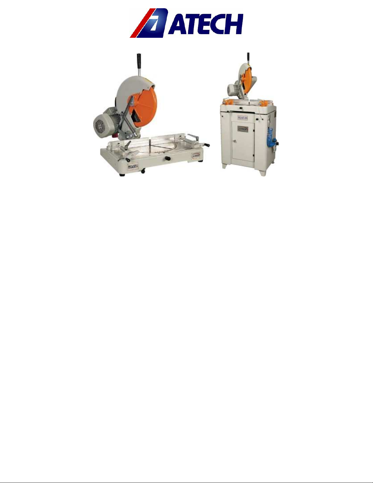
Portable miter saw for serial cutting of PVC, aluminum and wooden profiles in desired
angles. The operator has the possibility to adjust the cutting speed of the saw blade via
knob according to material type and size.
Cutting at fixed angles of 150-22.50-300-450-900, and at intermediate angles via fixing
arm. Machine has been designed according to CE Safety Directives.
PEGASUS-02 M / SKAT-02 M : Manual system with base and pneumatic clamps.
PEGASUS-02 P / SKAT-02 P : Portable manual system.
Operating and Safety Instructions

4
Please mention the below mentioned data in all your correspondence regarding the
machine with the manufacturer and/or your ATECH dealer.
*Machine model
*Machine’s serial number
*Voltage and frequency
*Name of dealer where machine was purchased
*Date of purchase
*Description of the machine fault
*Average daily operation period
Operating and Safety Instructions
5
PEGASUS-02 M
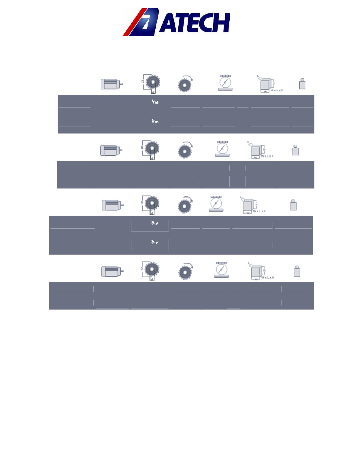
2.2. TECHNICAL FEATURES
Technical
Features
(American)
SKAT-02 P
SKAT-02 M
Technical
Features
(Metric)
SKAT-02 P
SKAT-02 M
Technical
Features
(American)
PEGASUS-02 P
PEGASUS-02 M
Technical
Features
(Metric)
PEGASUS-02 P
3 HP
220V/440V
60Hz
3 HP
220V/440V
60Hz
2,2kW
400V 50Hz
2,2kW
400V 50Hz
220V/440V
220V/440V
2,2kW
400V 50Hz
2,2kW
400V 50Hz
3 HP
60Hz
3 HP
60Hz
d=30-32mm
d=30-32mm
d=30-32mm
d=30-32mm
d=1 "
D=16"
d=1 "
D=16"
D=400mm
D=400mm
d=1 "
D=14"
d=1 "
D=14"
D=350mm
D=350mm
3000 rpm -- -- 26x24x30" 154 lbs
3000 rpm 90-120 psi
3000 rpm -- 66x60x76cm
3000 rpm 6-8 Bar
3000 rpm -- 26x24x30" 154 lbs
3000 rpm 90-120 psi 30x24x53" 253 lbs
3000 rpm -- 66x60x76cm 70kg
3000 rpm 6-8 Bar
1/min
0.2
CFM
5
l/min
30x24x53" 253 lbs
75x60x134
cm
5
75x60x134 cm 115 kg
70kg
115 kg
Operating and Safety Instructions

6
2.3. CUTTING DIAGRAM
PEGASUS Cutting
Diagram
SKAT Cutting
Diagram
Operating and Safety Instructions
7
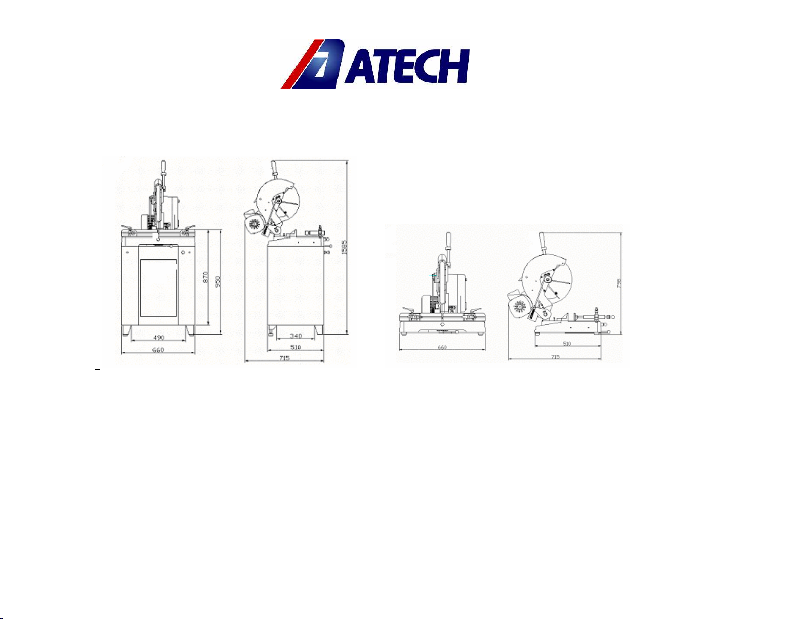
2.4. OVERALL DIMENSIONS
PEGASUS-02 M / SKAT-02 M PEGASUS-02 P / SKAT-02 P
Operating and Safety Instructions

8
2.5. PARTS LIST AND TECHNICAL DRAWINGS
PEGASUS
No.
20 142-026 FORK SHAFT 1
21 193-009 25x30x15 SINTER BUSHE 2
22 177-023 FORK ADJUSTMENT PIN 2
24 112-020 MOTOR SHAFT PULLEY 1
26 180-001 M6 x10 SCREW 1
28 112-017 BEARING COVER 2
30 141-112 BLADE SHAFT 1
31 112-019 BLADE SHAFT PULLEY 1
37 112-028 SHAFT SUPPORT PLATE 1
38 143-033 SPRING SHAFT 1
39 141-284 SPRING FORK ANKLE 1
40 141-271 FORK SHEET ANKLE 1
42 271-013 PROTECTION SPRING 1
44 141-269 FORK SHEET 1
45 145-025 PROTECTION PLATE 1
47 141-094 OUTER NUT WASHER 1
48 141-092 BLADE WASHER 1
49 114-018 BLADE INNER NUT WASHER 1
50 201-003 SAW BLADE 1
51 111-132 FORK 1
52 111-166 HEAD 1
54 141-093 WASHER 30x8x7 1
56 223-004 BAKELITE GRIP A5-12 1
59 111-167 PULLEY PROTECTION 1
60 141-135 GRIP 1
61 112-023 GRIP CONNECTION 1
64 141-108 PROTECTION ADAPTER 1
65 141-113 BLADE GUARD CONNECTION 1
66 111-169 GUARD HOUSING 1
67 111-170 BLADE GUARD 1
68 180-003 M6 x 16 SCREW 3
ORDER
No.
PART NAME QTY
Operating and Safety Instructions

9
No.
20 142-026 FORK SHAFT 1
21 193-009 25x30x15 SINTER BUSHE 2
22 177-023 FORK ADJUSTMENT PIN 2
24 112-104 MOTOR SHAFT PULLEY 1
26 180-001 M6 x10 SCREW 1
28 112-017 BEARING COVER 2
30 141-112 BLADE SHAFT 1
31 112-105 BLADE SHAFT PULLEY 1
37 112-028 SHAFT SUPPORT PLATE 1
38 143-050 SPRING SHAFT 1
39 141-284 SPRING FORK ANKLE 1
40 141-271 FORK SHEET ANKLE 1
42 271-013 PROTECTION SPRING 1
44 150-007 FORK SHEET 1
45 145-064 PROTECTION PLATE 1
47 141-094 OUTER NUT WASHER 1
48 141-092 BLADE WASHER 1
49 114-003 BLADE INNER NUT WASHER 1
50 201-004 SAW BLADE 1
51 111-132 FORK 1
52 111-243 HEAD 1
54 141-093 WASHER 30x8x7 1
56 223-004 BAKELITE GRIP A5-12 1
59 111-244 PULLEY HOUSING 1
60 141-135 GRIP 1
61 112-023 GRIP CONNECTION 1
64 150-028 GUARD ADAPTER 1
65 141-113 BLADE GUARD CONNECTION 1
66 111-169 GUARD HOUSING 1
67 111-245 BLADE GUARD 1
68 180-003 M6 x 16 SCREW 3
Order
No.
PART NAME QTY
SKAT
Operating and Safety Instructions

IMPORTANT
CAUTION !
3. SAFETY
3.1. SAFETY INFORMATION
The symbols shown hereunder are necessary to be read with special attention.
Not reading or observing of them may cause damage to the equipment or personal
injury.
The IMPORTANT symbol above is one telling to apply special care and to be careful at
carrying out the specified operation.
The CAUTION! Symbol above warns you against specific dangers, and requires to read the
text. Not observing may cause damage to the equipment.
DANGER WARNING
The above symbol DANGER WARNING, warns you against specific dangers, and you have
definitely to read them. Negligence may cause damage to the equipment and bodily
injury.
Read the user’s manual carefully before using the machine or carrying out maintenance
works.
3.2. ACCIDENT PREVENTION
3.2.1.
Our machines are manufactured in accordance with EN 60204-1 and EN 292-2 CE
safety directives, which cover national and international safety directives.
3.2.2.
It is the task of the employer to warn his staff against accident risks, to train them on
prevention of accidents, to provide for necessary safety equipment and devices for the
operator’s safety.
3.2.3.
Before starting to work with the machine, the operator should check the features of
the machine, learn all details of the machine's operation.
10
Operating and Safety Instructions

3.2.4.
Machine should be operated only by staff members, who have read and
understood the contents of this manual.
3.2.5.
All directives, recommendations and general safety rules contained in this manual
have to be observed fully. The machine cannot be operated in any way for purposes
other than those described herein. Otherwise, the manufacturer shall not be deemed
responsible for any damages or injuries. And such circumstances would lead to the
termination of the warranty.
3.3. GENERAL SAFETY INFORMATION
3.3.1
. The power cable should be led in such a way that nobody can step on it or
nothing can be placed on it. Special care has to be taken regarding the inlet and
outlet sockets.
3.3.2.
If the power cable should be damaged during operation, don't touch and
unplug it. Never use damaged power cables.
3.3.3.
Don’t overload machines for drilling and cutting. Your machine will operate
more safely with power supply in accordance with the stipulated values.
3.3.4.
Don’t place your hands between parts in motion.
3.3.5.
Use protective eye glasses and ear plugs. Don't wear oversize clothes and
jewels. These can be caught by moving parts.
3.3.6.
Keep your working place always clean, dry and tidy for accident prevention
and safe operation.
3.3.7.
Use correct illumination for the safety of the operator. (ISO 8995-89 The Lighting
of Indoor Work Systems)
3.3.8.
Don't leave anything on the machine.
Operating and Safety Instructions
11

IMPORTANT
3.3.9.
Don’t use any materials other than those recommended by the manufacturer
for cutting operations on the machine.
3.3.10.
or vice.
3.3.11.
3.3.12.
maintenance and replacement of accessories. Check the plug and cable regularly.
If damaged, let it replace by a qualified electrician. Keep handles and grips free of
any oil and grease.
3.3.13.
3.3.14.
operating the machine.
3.3.15.
extension cables.
3.3.16.
accidents may occur.
3.3.17.
protective devices and tools, ensure that they work properly. All conditions have to
be fulfilled in order to ensure proper operation of your machine. Damaged
protective parts and equipment have to be replaced or repaired properly (by the
manufacturer or dealer).
3.3.18.
3.3.19.
electric connections.
4. TRANSPORT OF THE MACHINE
* The transport should be done by qualified personnel only.
The machine should be transported by lifting with proper equipment (not touching the
ground during the transport).
Don’t lift the machine before ensuring that lifting devices or other equipment is placed
properly under the machine.
Ensure that the work piece is clamped appropriately by the machine's clamp
Ensure safe working position, always keep your balance.
Keep your machine always clean for safe operation. Follow the instructions at
Unplug first, before conducting and maintenance works.
Ensure that any keys or adjustment tools have been removed before
If you are required to operate the machine outside, use only appropriate
Repairs should be carried out by qualified technicians only. Otherwise,
Before starting a new operation, check the appropriate function of
Don’t use machines with improper functioning buttons and switches.
Don’t keep flammable, combustive liquids and materials next to the machine and
12
Operating and Safety Instructions

5. INSTALLATION OF THE MACHINE
The machine should be located at least 40 cm in front of the back wall. The machine is
equipped with a burr collection bag connector and power supply socket on the back
side.
5.1. PREPARATION
5.1.1.
The outer dimensions of the machine are stipulated in the Dimensions page (Page
6). The ground, where the machine will be placed, should be even, solid enough to bear
the weight of the machine.
5.1.2.
At the miter saws PEGASUS - SKAT all parts are delivered by the manufacturer ready
for use.
5.1.3.
If you have purchased a conveyor, which is offered an option, connect to either
side of the machine as shown in Illustration 1.
5.1.4.
Before starting the machine, remove the transport safety part as shown in Illustration
2.
Illustration-1
Head Fixing
Plate
Illustration-2
Operating and Safety Instructions
13

CAUTION !
5.2. ELECTRIC CONNECTION
5.2.1.
The three-phase power cable socket has to be in accordance with the socket on
the machine.
5.2.2.
Use a connection cable socket in accordance with the CE Safety Directives.
5.2.3.
Check the inlet power supply before powering the machine. See Page 19 Item 3.8.3.
* The socket connections have to be made by a qualified electrician, the rotation
direction of the saw blade has to be observed by starting the machine. If the saw blade
rotates in reverse direction, the socket connections have to be checked and reconnected properly.
**If the saw blade rotates in reverse direction, it will cause danger for the operator and the
equipment.
To correct the rotation direction of the saw blade, insert the electric power socket of the
machine to the 3-phase slot, which has been prepared before, and follow these
instructions:
1. Press the Motor Start Button to operate the saw blade.
2. Press the cutting head down until the blade guard opens.
3. Press the Stop button. Observe the rotation direction of the saw blade through the open
part of the blade guard.
4. The correct direction of the saw blade rotation is shown in Figure 3.
If the saw blade rotates in reverse direction:
Figure-3
14
Operating and Safety Instructions

IMPORTANT
The electric socket connections have to be checked and corrected by a qualified
electrician.
The rotation direction of the saw blade should not be defined before testing.
6. MACHINE SAFETY INFORMATION
6.8.1.
It is not allowed to operate the machine with the protective cover and other
protective equipment removed.
6.8.2.
Your machine operates with 220V/440V ~ 3-Phase 60Hz (400V ~ 3-Phase 50Hz) . Let
the electric installation of your machine carry out by a qualified electrician only.
6.8.3
. Lifting, installation, electric, pneumatic maintenance of the machine should be
carried out by qualified personnel only.
6.8.4.
Routine maintenance and scheduled maintenance should be carried out by
qualified personnel after unplugging the machine and disconnecting the air supply first.
6.8.5.
Ensure that the machine has been cleaned, tested and maintained before starting
to operate.
6.8.6.
Check the safety devices, power cable and moving parts regularly. Don’t operate
the machine before having replaced defective safety devices or faulty parts.
6.8.7.
Never replace the saw blade before unplugging first.
6.8.8.
Keep foreign materials away from the working area of the machine, keep away
from the machine’s moving parts.
The safety data have been defined above. In order to prevent physical damage or
damage to the equipment, please read the safety information carefully and keep the
manual always in an easy accessible place.
15
Operating and Safety Instructions

CAUTION !
IMPORTANT
7. OPERATION
The miter saws PEGASUS / SKAT cut non-ferrous aluminum, PVC profiles and PVC materials.
The operator adjusts (manually via knob) the cutting speed of the saw blade according to
the material type to be cut. Inner and outer sharp edges of the carbide tipped circular
saw blade ensures high quality clean cutting results. The cutting length can be precisely
read and adjusted using the measuring tape fixed to the back fence.
Start the machine only after proper clamping of the work piece to be cut.
The machine is equipped with horizontal clamps. The clamping positions, either manual or
pneumatic clamps, can be adjusted comfortably according to the material.
At manual clamps the clamp shaft can be moved 50 mm.
At pneumatic clamps the clamp piston can be moved 55 mm.
The clamping cylinders have to be outside of the saw blade moving area. (See Illustration
6 and 7)
The air pressure of the machine (pneumatic model) has to balance 6-8 Bar (90-120 psi)
pressure. Don’t operate the machine with an air pressure lower than 6 Bar.
7.1. ADJUSTING THE AIR PRESSURE OF PNEUMATIC CLAMPS
7.1.1.
Pull the adjustment button of the conditioner upwards.
a-
Turning the adjustment button in clockwise direction increases the pressure
b-
Turning the adjustment button in counter clockwise direction decreases the pressure
c-
Once you read 6-8 Bar (90-120 psi)on the manometer, push the adjustment button of
the conditioner down and lock it in that position.
16
Operating and Safety Instructions

Manometer
Pressure
Adjustment
Air Pressure and
Water Discharge
Screw
7.1.1.
Place the material to be cut on the machine table, take the measure the cutting
length using the measuring tape on the back fence, and clamp the work piece
(pneumatically or manually).
7.1.2.
Start to operate the saw blade by pressing the Start button.
7.1.4.
Carry out the cutting operation by pressing down the cutting head holding the grip.
7.1.5.
After cutting off the material, bring the cutting grip to its original position, press the
Stop button. The saw blade will come to a full stop within 15 sec.
7.1.6.
Release the clamps (manually or pneumatically) and take out the cut work piece.
7.1.7.
The conditioner unit collects the water within the air system in a receptacle in order
to prevent damage to the pneumatic system components. Discharge this water
periodically (at the end of the working day) by pressing or opening the button under the
conditioner.
7.1.7.
The manufacturer recommends to use the following oils with the conditioner: TELLUS
C 10 / BP ENERGOL HLP 10/ MOBIL DTE LIGHT / PETROL OFISI SPINDURA 10.
Oil Depot
Oil Filling Tap
Illustration 3
Don’t operate the saw while it touches the work piece. The saw must be operated only
when the head is in the top position.
Operating and Safety Instructions
17

stration 5
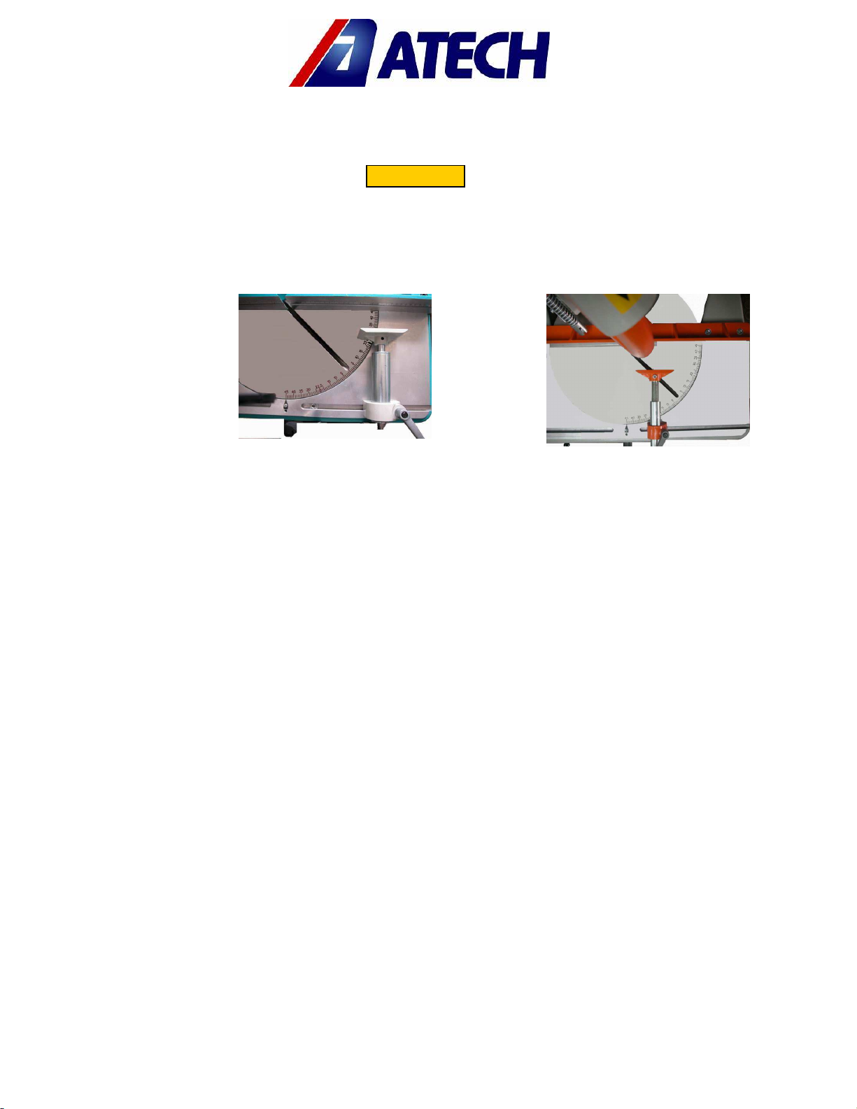
7.2. MITER CUT:
7.2.1
. Press the saw blade down until it touches the cutting slot of the table.
7.2.2
. Pull out the snap pin from its slot. (See Illustration 4)
7.2.3.
Pull the table locking Bar to the left to unlock. (See Illustration 4)
7.2.3.
Adjust the desired angle by turning the cutting head to the right or left. (See
Illustration 5)
7.2.4.
The cutting angles 15°-22.5°-30°-45° are fixed by releasing the snap. Pull the table
locking handle to the right and fix the table (See Illustration 5)
Snap Pin
Table Locking
Table Locking
Handle (Locked)
Illustration 4 Illu
7.2.5.
At intermediate angles (5°-10°-15°-35°-40° …) lock the table by pulling the table
locking handle to the right.
Handle(Unlocked)
No Stock No / Part Name Qty
141-112 BLADE SHAFT 1
30
112-019 BLADE SHAFT PULLEY 1
31
141-094 OUTER NUT WASHER 1
47
141-092 BLADE WASHER 1
48
114-018 BLADE INNER NUT
49
WASHER
201-003 350 mm SAW BLADE 1
50
201-004 400 mm SAW BLADE 1
50
111-166 PEGASUS HEAD 1
52
111-243 SKAT I HEAD 1
52
141-093 WASHER 30x8x7 1
54
172-025 M8x16 HEXAG. SCREW 1
55
1
Operating and Safety Instructions
18
CAUTION !
WRONG
Always ensure that the clamps are positioned outside of the operation area of the saw
blade.
CORRECT
8. SAFE INSTALLATION OF THE SAW BLADE
8.1
To remove the circular saw blade from the blade shaft, follow the instructions below.
8.1.1.
Remove the M8 screw (Figure 4, No. 55) by turning it counter clockwise with a 8 mm
hexagonal key. (Hold the saw blade shaft at the opposite end with a 17 mm wrench key
and prevent so that the shaft turns.
8.1.2.
Remove the washer No. 54 and the outer nut washer No. 47.
8.1.3.
Take out the saw blade carefully.
8.1.4.
Insert the new saw blade on the saw blade shaft, ensuring correct rotation direction.
8.1.5.
Insert the other parts (washer, outer nut washer) in reverse order as removal.
8.1.6.
Tighten the M8 screw while holding the blade shaft with a 17 mm wrench key in fix
position. It is necessary to sharpen / replace the saw blade in certain intervals depending
on the cutting material.
8.1.7.
If the cut material leaves burr after the cutting operation or if the saw blade is
strained, it needs to be sharpened / replaced.
Figure-4
19
Operating and Safety Instructions

.
8.1.8. When replacing the saw blade, use the part of the saw blade washer No. 48, which is
in accordance with the saw blade shaft diameter. The outer diameter of the blade washer
is 30 and 32 mm.
9. MAINTENANCE
9.1. PERIODIC CHECKS
9.1.1.
Ensure that the table and all kind of parts are clean and dry. Degrease and dry the
table. Especially ensure that the holding grips are clean and dry.
9.1.2.
Remove all burr, chip and foreign materials from all surfaces of the machine. Use
protective eye glasses.
9.1.3.
Check the saw blade before each use. Turn the saw blade carefully (after removing
the blade guard) to see the teeth of the saw blade. Replace the saw blade if it is
damaged.
9.1.4.
Check the pressure of the air pressure system. If necessary, adjust the air pressure
between 6-8 Bar.
(See Illustration 3)
9.1.5.
Check the air pressure filters and the oil level of the conditioner. Fill up if the oil level
is low. (See Illustration 3)
Unplug and disconnect the air pressure connections first, before carrying out these works.
Operating and Safety Instructions
20

9.2. MAINTENANCE AT THE END OF THE WORKING DAY
9.2.1.
Disconnect electric and pneumatic connections. (Main Switch must be on “0”
position)
9.2.2.
Remove all burr, chip and foreign materials from the machine surfaces. If it is
necessary to clean the inside of the blade guard, remove the front cover, use gloves to
protect your hands from the sharp edges of the blade.
9.2.3.
If water or water based liquids were used during cutting, dry the machine with a dry
cloth after the operation is finished.
9.2.4.
Apply a thin layer of machine oil to protect the table against corrosion. If the
machine will not be used for a long time, lubricate with a protective oil.
9.2.5.
Don’t use materials for cleaning the machine, which could damage its paint.
9.2.6.
Lubricate both surfaces of the saw blade with machine oil in order to protect it
against corrosion.
10. TROUBLESHOOTING GUIDE
Here are some recommendations for solving urgent problems. If the trouble cannot be
solved, or if you have a problem other than those described hereunder, please contact
our technical service or your nearest dealer.
TROUBLE CAUSES REMEDY
Low surface quality (at aluminum and
similar materials) :
Rough surface,
Large chip,
Not homogenous surface,
Saw blade traces visible
Not cooling the saw blade surfaces
Using of damaged or blunt saw blade
Lubricating the saw blade cutting
surfaces,
Using of cooling liquid
Check the saw blade teeth. Replace
if necessary.
Saw blade moves to quick
Motor does not work (Start button is
pressed, not working)
Motor is working but the pneumatic
clamp pistons do not work.
The saw blade rotates in reverse
direction.
No power supply to the machine. Check the electric cable
The air supply connections are missing, or the air
pressure is too low.
The electric connection, the power cable or the
connection at the panel is wrong.
The cutting speed is too high for the
material. Decrease the cutting
speed.
connections.
Check the electric power sockets.
Check the air compressor
connections.
Adjust the air pressure between 6-8
Bar on the conditioner.
Let the electric connections carry
out by a qualified electrician.
Operating and Safety Instructions
21

11. ELECTRIC / PNEUMATIC COMPONENTS
11.1 ELECTRIC COMPONENTS
ORDER No. PART NAME QUANTITY
163-002 MOTOR QS 90 L 2A H 2.2 kW 400V 3 N PE 50 Hz 1
161-005 LE1-M35Q712 MOTOR PATCHER 1
164-013 4x1,5 mm POWER CABLE H0 7RN-F 3,5 m
11.2 PNEUMATIC COMPONENTS
165-050 ELECTRIC PLUG 1
ORDER No. PART NAME QUANTITY
241-009 FRC-1/8-D-MINI CONDITIONER 1
241-023 SV-1/4-3/2-D-O VALVE 1
550-003 PNEUMATIC CLAMP 2
Operating and Safety Instructions
22
 Loading...