

Page 1
R&S®ZVA
Vector Network Analyzer
Specifications
Data Sheet | 10.00
Test & Measurement
Page 2

Version 10.00, May 2012
CONTENTS
Definitions ....................................................................................................................................................................... 3
Specifications .................................................................................................................................................................. 4
Measurement range ................................................................................................................................................................................ 4
Measurement speed ............................................................................................................................................................................... 8
Measurement accuracy ......................................................................................................................................................................... 10
Effective system data ............................................................................................................................................................................ 19
Test port output ..................................................................................................................................................................................... 21
Test port input ....................................................................................................................................................................................... 25
Additional front panel connectors .......................................................................................................................................................... 29
Optional front panel connectors ............................................................................................................................................................ 29
Display .................................................................................................................................................................................................. 29
Rear panel connectors .......................................................................................................................................................................... 29
Options .......................................................................................................................................................................... 31
General data .................................................................................................................................................................. 35
Ordering information .................................................................................................................................................... 36
2 Rohde & Schwarz R&S
®
ZVA Vector Network Analyzer
Page 3
Version 10.00, May 2012
Definitions
General
Product data applies under the following conditions:
Three hours storage at ambient temperature followed by 90 minutes warm-up operation
Specified environmental conditions met
Recommended calibration interval adhered to
All internal automatic adjustments performed, if applicable
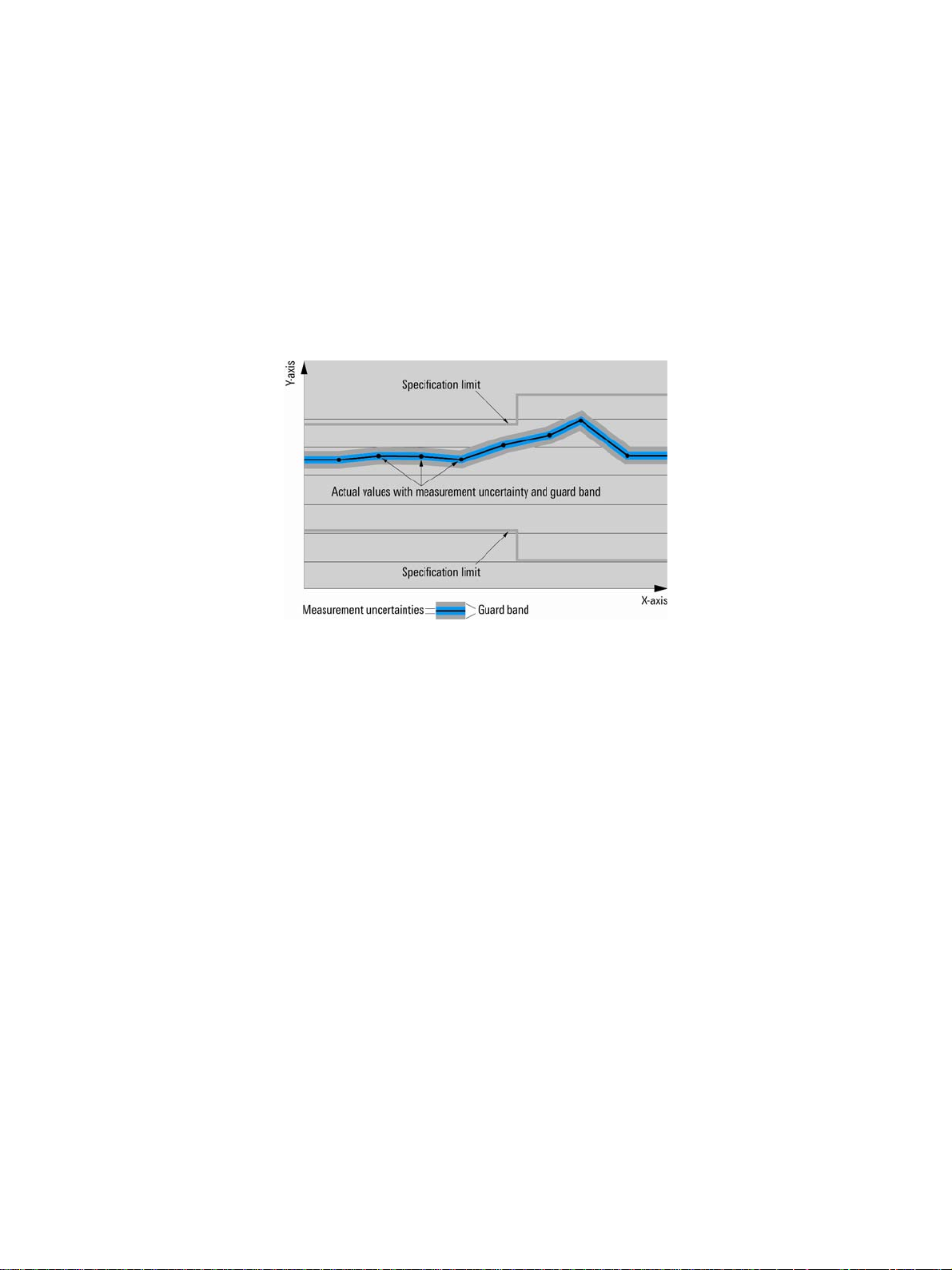
Specifications with limits
Represent warranted product performance by means of a range of values for the specified parameter. These specifications are
marked with limiting symbols such as <, ≤, >, ≥, ±, or descriptions such as maximum, limit of, minimum. Compliance is ensured by
testing or is derived from the design. Test limits are narrowed by guard bands to take into account measurement uncertainties, drift
and aging, if applicable.
Specifications without limits
Represent warranted product performance for the specified parameter. These specifications are not specially marked and represent
values with no or negligible deviations from the given value (e.g. dimensions or resolution of a setting parameter). Compliance is
ensured by design.
Typical data (typ.)
Characterizes product performance by means of representative information for the given parameter. When marked with <, > or as a
range, it represents the performance met by approximately 80 % of the instruments at production time. Otherwise, it represents the
mean value.
Nominal values (nom.)
Characterize product performance by means of a representative value for the given parameter (e.g. nominal impedance). In contrast to
typical data, a statistical evaluation does not take place and the parameter is not tested during production.
Measured values (meas.)
Characterize expected product performance by means of measurement results gained from individual samples.
Uncertainties
Represent limits of measurement uncertainty for a given measurand. Uncertainty is defined with a coverage factor of 2 and has been
calculated in line with the rules of the Guide to the Expression of Uncertainty in Measurement (GUM), taking into account
environmental conditions, aging, wear and tear.
Typical data as well as nominal and measured values are not warranted by Rohde & Schwarz.
Rohde & Schwarz R&S
®
ZVA Vector Network Analyzer 3
Page 4
Version 10.00, May 2012
–
–
Specifications
Specifications apply under the following conditions: 90 minutes warm-up time at ambient temperature, specified environmental
conditions met, calibration cycle adhered to, and all internal automatic adjustments performed. "Typical values" are designated with
the abbreviation "typ.". These values are verified during the final test but are not assured by Rohde & Schwarz. "Nominal values" are
design parameters that are not assured by Rohde & Schwarz. These values are verified during product development but are not
specifically tested during production.
Unless otherwise stated, specifications apply to test ports and a nominal source power of –10 dBm.
Measurement range
Impedance 50 Ω
Test port connector R&S®ZVA8 type N, female
R&S®ZVA24 3.5 mm, male, ruggedized
R&S®ZVA40 2.92 mm, male, ruggedized
R&S®ZVA40 2.4 mm, male, ruggedized
R&S®ZVA50 2.4 mm, male, ruggedized
R&S®ZVA67 1.85 mm, male, ruggedized
Number of test ports 2 or 4
Frequency range R&S®ZVA8 300 kHz to 8 GHz
R&S®ZVA24 10 MHz to 24 GHz
R&S®ZVA40 10 MHz to 40 GHz
R&S®ZVA50 10 MHz to 50 GHz
R&S®ZVA67 10 MHz to 67 GHz
Static frequency accuracy without optional oven quartz 8×10
with optional oven quartz 1×10
Frequency resolution 1 Hz
Number of measurement points user-selectable 1 to 60001
Measurement bandwidths 1/2/5 steps 1 Hz to 1 MHz
Dynamic range of the R&S®ZVA8
(without optional step attenuators
and without optional direct
generator/receiver access)
from PORT 1 to PORT 2 and
from PORT 3 to PORT 4
300 kHz to 50 MHz > 100 dB, typ. 110 dB
50 MHz to 100 MHz > 120 dB, typ. 130 dB
100 MHz to 4 GHz > 130 dB, typ. 140 dB
4 GHz to 7 GHz > 125 dB, typ. 135 dB
7 GHz to 8 GHz > 120 dB, typ. 130 dB
Dynamic range of the R&S®ZVA24
(without optional step attenuators
and without optional direct
generator/receiver access)
from PORT 1 to PORT 2 and
from PORT 3 to PORT 4
10 MHz to 100 MHz > 90 dB, typ. 105 dB
100 MHz to 700 MHz > 105 dB, typ. 120 dB
700 MHz to 2 GHz > 125 dB, typ. 130 dB
2 GHz to 13 GHz > 130 dB, typ. 135 dB
13 GHz to 24 GHz > 125 dB, typ. 130 dB
Dynamic range of the R&S®ZVA40
(without optional step attenuators
and without optional direct
generator/receiver access)
from PORT 1 to PORT 2 and
from PORT 3 to PORT 4
10 MHz to 50 MHz > 90 dB, typ. 100 dB
50 MHz to 500 MHz > 105 dB, typ. 115 dB
500 MHz to 2 GHz > 125 dB, typ. 135 dB
2 GHz to 20 GHz > 130 dB, typ. 140 dB
20 GHz to 24 GHz > 125 dB, typ. 135 dB
24 GHz to 32 GHz > 120 dB, typ. 130 dB
32 GHz to 40 GHz > 118 dB, typ. 125 dB
Dynamic range of the R&S®ZVA50
(without optional step attenuators
and without optional direct
generator/receiver access)
from PORT 1 to PORT 2 and
from PORT 3 to PORT 4
10 MHz to 50 MHz > 90 dB, typ. 100 dB
50 MHz to 500 MHz > 105 dB, typ. 115 dB
500 MHz to 2 GHz > 125 dB, typ. 135 dB
2 GHz to 20 GHz > 130 dB, typ. 140 dB
20 GHz to 24 GHz > 125 dB, typ. 135 dB
24 GHz to 40 GHz > 120 dB, typ. 130 dB
40 GHz to 45 GHz > 115 dB, typ. 125 dB
45 GHz to 50 GHz > 110 dB, typ. 120 dB
6
7
®
4 Rohde & Schwarz R&S
ZVA Vector Network Analyzer
Page 5
Version 10.00, May 2012
®
Dynamic range of the R&S
ZVA67
(without optional step attenuators
and without optional direct
generator/receiver access)
from PORT 1 to PORT 2 and
from PORT 3 to PORT 4
10 MHz to 50 MHz > 70 dB, typ. 90 dB
50 MHz to 500 MHz > 110 dB, typ. 125 dB
500 MHz to 2 GHz > 120 dB, typ. 130 dB
2 GHz to 8 GHz > 130 dB, typ. 140 dB
8 GHz to 12 GHz > 125 dB, typ. 140 dB
12 GHz to 24 GHz > 130 dB, typ. 140 dB
24 GHz to 32 GHz > 120 dB, typ. 130 dB
32 GHz to 40 GHz > 115 dB, typ. 125 dB
40 GHz to 50 GHz > 115 dB, typ. 125 dB
50 GHz to 65 GHz > 107 dB, typ. 115 dB
65 GHz to 67 GHz > 105 dB, typ. 115 dB
67 GHz to 70 GHz typ. 103 dB
The dynamic range is defined as the difference between the actually available maximum source power and the RMS value of the
data trace of the transmission magnitude, which is produced by noise and crosstalk with the test ports short-circuited. The
specification is valid without system error correction and at 10 Hz measurement bandwidth. The dynamic range can be increased by
using a measurement bandwidth of 1 Hz. For the R&S
®
ZVA67 at single frequencies below 2.5 GHz, the dynamic range may be
affected by spurious signals.
Dynamic range at optional measurement
input (direct generator/receiver access
option) of the R&S
®
ZVA8
from PORT 1 to MEAS 2 IN
300 kHz to 10 MHz typ. > 125 dB
10 MHz to 100 MHz typ. > 135 dB
100 MHz to 8 GHz typ. > 145 dB
Dynamic range at optional measurement
input (direct generator/receiver access
option) of the R&S
®
ZVA24
from PORT 1 to MEAS 2 IN
10 MHz to 100 MHz typ. > 135 dB
100 MHz to 13 GHz typ. > 145 dB
13 GHz to 20 GHz typ. > 140 dB
20 GHz to 24 GHz typ. > 130 dB
Dynamic range at optional measurement
input (direct generator/receiver access
option) of the R&S
®
ZVA40
from PORT 1 to MEAS 2 IN
10 MHz to 100 MHz typ. > 140 dB
100 MHz to 20 GHz typ. > 150 dB
20 GHz to 24 GHz typ. > 140 dB
24 GHz to 32 GHz typ. > 130 dB
32 GHz to 40 GHz typ. > 120 dB
Dynamic range at optional measurement
input (direct generator/receiver access
option) of the R&S
®
ZVA50
from PORT 1 to MEAS 2 IN
10 MHz to 100 MHz typ. > 140 dB
100 MHz to 20 GHz typ. > 150 dB
20 GHz to 24 GHz typ. > 145 dB
24 GHz to 32 GHz typ. > 140 dB
32 GHz to 40 GHz typ. > 135 dB
40 GHz to 50 GHz typ. > 130 dB
Dynamic range at optional measurement
input (direct generator/receiver access
option) of the R&S
®
ZVA67
from PORT 1 to MEAS 2 IN
10 MHz to 100 MHz typ. > 140 dB
100 MHz to 20 GHz typ. > 145 dB
20 GHz to 24 GHz typ. > 145 dB
24 GHz to 32 GHz typ. > 140 dB
32 GHz to 40 GHz typ. > 135 dB
40 GHz to 50 GHz typ. > 130 dB
50 GHz to 67 GHz typ. > 125 dB
®
Rohde & Schwarz R&S
ZVA Vector Network Analyzer 5
Page 6
Version 10.00, May 2012
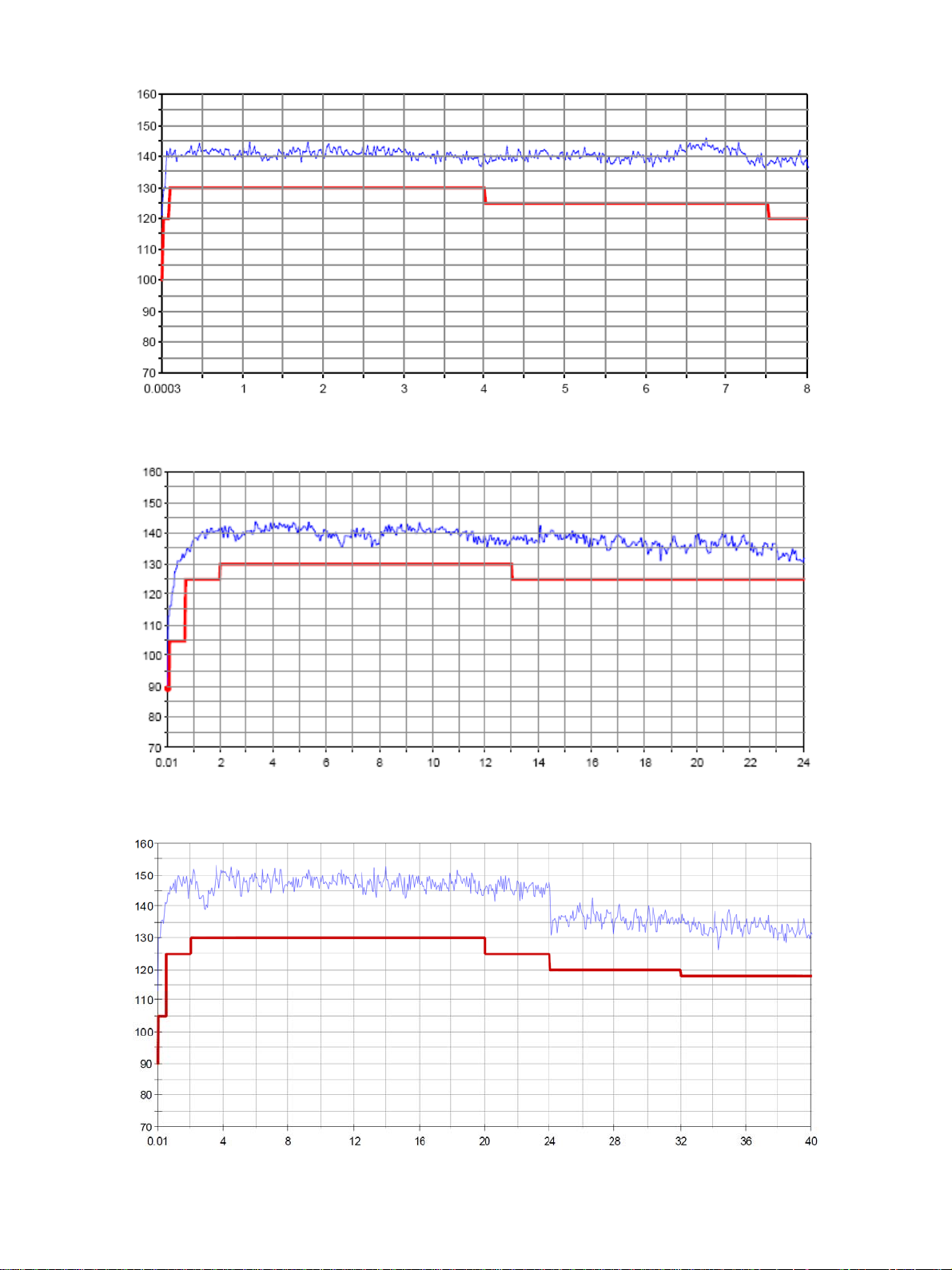
Diagram: Dynamic range in dB versus frequency in GHz of the R&S
®
ZVA8.
Diagram: Dynamic range in dB versus frequency in GHz of the R&S
Diagram: Dynamic range in dB versus frequency in GHz of the R&S
6 Rohde & Schwarz R&S
®
ZVA Vector Network Analyzer
®
ZVA24.
®
ZVA40.
Page 7
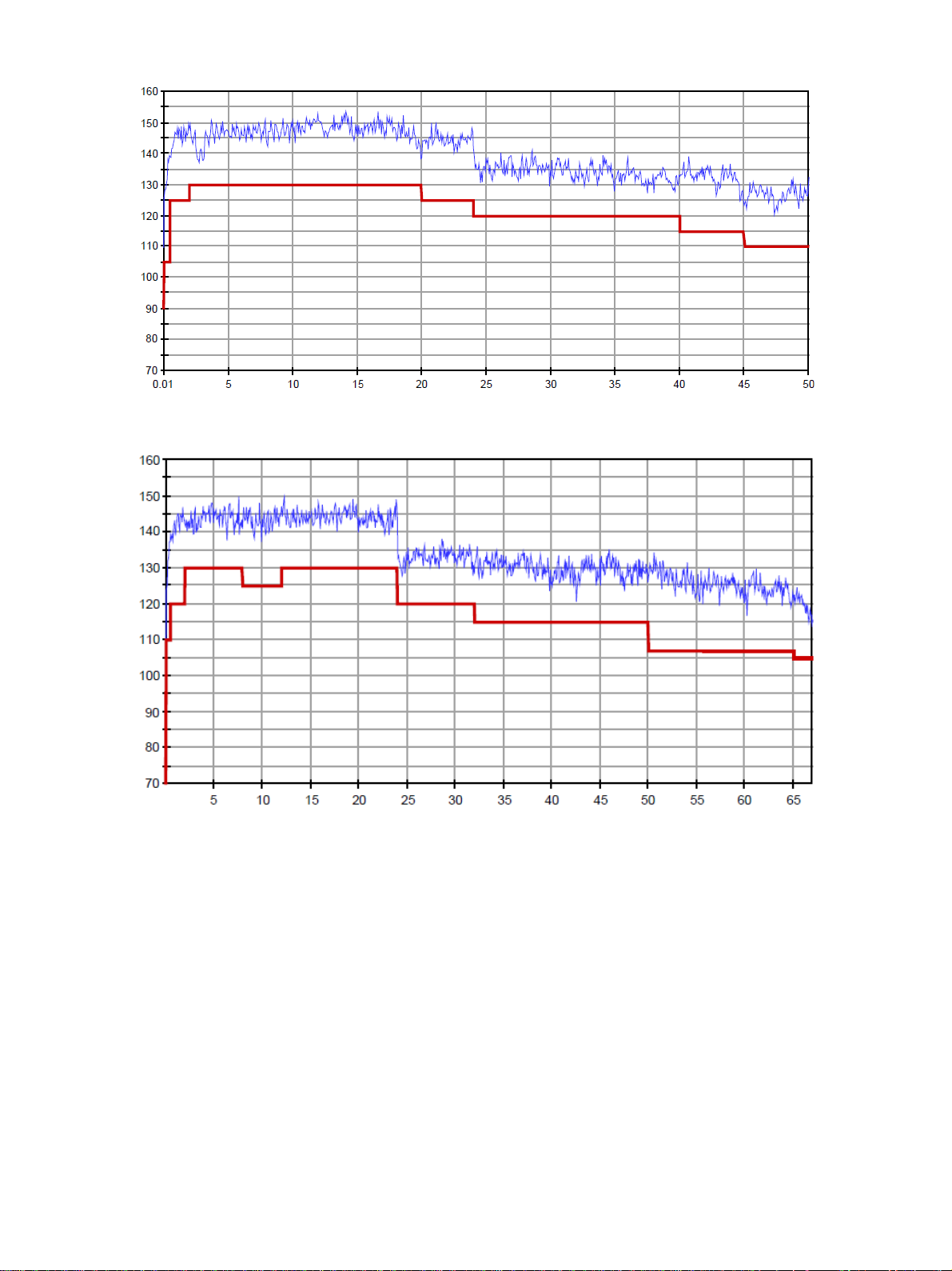
Diagram: Dynamic range in dB versus frequency in GHz of the R&S
®
ZVA50.
Version 10.00, May 2012
Diagram: Dynamic range in dB versus frequency in GHz of the R&S
Rohde & Schwarz R&S
®
ZVA67.
®
ZVA Vector Network Analyzer 7
Page 8
Version 10.00, May 2012
®
Measurement speed
Measurement time per point CW mode,
1 MHz measurement bandwidth
Data transfer time for 201 measurements points
via IEC/IEEE bus < 2.9 ms
via VX11 over 100 Mbit/s LAN < 1.3 ms
via RSIB over 100 Mbit/s LAN < 0.7 ms
Switching time between channels with no more than 2001 points < 1 ms
Switching time between two preloaded
with no more than 2001 points < 10 ms
instrument settings
< 3.5 µs
Sweep times of the R&S
ZVA8, R&S®ZVA24, R&S®ZVA40 and R&S®ZVA50
Sweep times depend on the number of measurement points, the measurement bandwidth, and the start and stop frequencies.
They include times for retrace and internal band switching and are valid with ALC and display switched off.
Number of measurement points 51 101 201 401 801 1601
R&S®ZVA with start frequency 5 GHz, stop frequency 5.2 GHz
For a measurement bandwidth of 100 kHz
With full one-port calibration or
with correction switched off
2.6 ms
4.0 ms
6.8 ms
12 ms
23 ms
42 ms
With TOSM calibration 3.8 ms 6.5 ms 11.6 ms 22 ms 41 ms 124 ms
For a measurement bandwidth of 1 MHz
With full one-port calibration or
with correction switched off
2.1 ms
3.0 ms
4.7 ms
8.0 ms
15 ms
26 ms
With TOSM calibration 2.8 ms 4.5 ms 7.5 ms 14 ms 26 ms 94 ms
R&S®ZVA with start frequency 6 GHz, stop frequency 8 GHz
For a measurement bandwidth of 100 kHz
With full one-port calibration or
with correction switched off
3.6 ms
6.4 ms
11.5 ms
19 ms
31 ms
50 ms
With TOSM calibration 4.8 ms 8.9 ms 16.3 ms 29 ms 49 ms 132 ms
For a measurement bandwidth of 1 MHz
With full one-port calibration or
with correction switched off
3.1 ms
5.4 ms
9.4 ms
14.7 ms
23 ms
35 ms
With TOSM calibration 3.8 ms 6.8 ms 12.2 ms 20.5 ms 33 ms 103 ms
R&S®ZVA8 with start frequency 10 MHz and stop frequency 8 GHz
®
R&S
ZVA24 with start frequency 10 MHz and stop frequency 24 GHz
®
R&S
ZVA40 with start frequency 10 MHz and stop frequency 40 GHz
®
R&S
ZVA50 with start frequency 10 MHz and stop frequency 50 GHz
For a measurement bandwidth of 100 kHz
With full one-port calibration or
with correction switched off
8.6 ms
13 ms
19.4 ms
32 ms
55 ms
92 ms
With TOSM calibration 9.9 ms 15.5 ms 25 ms 41 ms 74 ms 173 ms
For a measurement bandwidth of 1 MHz
With full one-port calibration or
with correction switched off
8.2 ms
12 ms
17.4 ms
28 ms
47 ms
75 ms
With TOSM calibration 8.8 ms 13.4 ms 20.2 ms 33 ms 57 ms 143 ms
®
8 Rohde & Schwarz R&S
ZVA Vector Network Analyzer
Page 9
Version 10.00, May 2012
®
Sweep times of the R&S
ZVA67
Sweep times depend on the number of measurement points, the measurement bandwidth, and the start and stop frequencies.
They include times for retrace and internal band switching and are valid with ALC and display switched off.
Number of measurement points 51 101 201 401 801 1601
R&S®ZVA67 with start frequency 6 GHz, stop frequency 12 GHz
For a measurement bandwidth of 100 kHz
With full one-port calibration or
with correction switched off
2 ms
3 ms
6 ms
11 ms
21 ms
42 ms
With TOSM calibration 4 ms 6 ms 12 ms 22 ms 42 ms 125 ms
For a measurement bandwidth of 1 MHz
With full one-port calibration or
with correction switched off
1.5 ms
2 ms
4 ms
7 ms
13 ms
25 ms
With TOSM calibration 3 ms 4 ms 8 ms 14 ms 26 ms 90 ms
R&S®ZVA67 with start frequency 10 MHz and stop frequency 67 GHz
For a measurement bandwidth of 100 kHz
With full one-port calibration or
with correction switched off
3 ms
4 ms
7 ms
12 ms
22 ms
42 ms
With TOSM calibration 6 ms 8 ms 14 ms 24 ms 44 ms 125 ms
For a measurement bandwidth of 1 MHz
With full one-port calibration or
with correction switched off
2.5 ms
3 ms
5 ms
8 ms
14 ms
25 ms
With TOSM calibration 5 ms 6 ms 10 ms 16 ms 28 ms 90 ms
®
Rohde & Schwarz R&S
ZVA Vector Network Analyzer 9
Page 10
Version 10.00, May 2012
Measurement accuracy
This data is valid between +18 °C and +28 °C, provided the temperature has not varied by more than 1 K after calibration. Validity of
the data is conditional on the use of a suitable calibration kit. This calibration kit is used to achieve the effective system data specified
below. Frequency points, measurement bandwidth, and sweep time have to be identical for measurement and calibration (no
interpolation allowed).
Accuracy of transmission measurements
R&S®ZVA8
300 kHz to 1 MHz for +15 dB to –45 dB < 1 dB or < 6°
1 MHz to 50 MHz for +15 dB to –30 dB < 0.2 dB or < 2°
for –30 dB to –45 dB < 1 dB or < 6°
50 MHz to 8 GHz for +15 dB to +5 dB < 0.2 dB or < 2°
for +5 dB to –55 dB < 0.1 dB or < 1°
for –55 dB to –70 dB < 0.2 dB or < 2°
for –70 dB to –85 dB < 1 dB or < 6°
R&S®ZVA24
10 MHz to 50 MHz for +15 dB to –30 dB < 1 dB or < 6°
50 MHz to 400 MHz for +15 dB to –30 dB < 0.2 dB or < 2°
for –30 dB to –45 dB < 1 dB or < 6°
400 MHz to 700 MHz for +15 dB to –50 dB < 0.2 dB or < 2°
for –50 dB to –65 dB < 1 dB or < 6°
700 MHz to 24 GHz for +15 dB to +5 dB < 0.2 dB or < 2°
for +5 dB to –55 dB < 0.1 dB or < 1°
for –55 dB to –70 dB < 0.2 dB or < 2°
for –70 dB to –85 dB < 1 dB or < 6°
R&S®ZVA40
10 MHz to 50 MHz for +15 dB to –30 dB < 1 dB or < 6°
50 MHz to 250 MHz for +15 dB to –30 dB < 0.2 dB or < 2°
for –30 dB to –45 dB < 1 dB or < 6°
250 MHz to 700 MHz for +15 dB to +5 dB < 0.3 dB or < 3°
for +5 dB to –65 dB < 0.2 dB or < 2°
for –65 dB to –80 dB < 1 dB or < 6°
700 MHz to 2 GHz for +15 dB to +5 dB < 0.3 dB or < 3°
for +5 dB to –50 dB < 0.1 dB or < 1°
for –50 dB to –65 dB < 0.2 dB or < 2°
for –65 dB to –80 dB < 1 dB or < 6°
2 GHz to 24 GHz for +15 dB to +5 dB < 0.3 dB or < 3°
for +5 dB to –55 dB < 0.1 dB or < 1°
for –55 dB to –70 dB < 0.2 dB or < 2°
for –70 dB to –85 dB < 1 dB or < 6°
24 GHz to 32 GHz for +15 dB to +5 dB < 0.3 dB or < 3°
for +5 dB to –45 dB < 0.2 dB or < 2°
for –45 dB to –60 dB < 0.3 dB or < 3°
for –60 dB to –75 dB < 1 dB or < 6°
32 GHz to 40 GHz for +15 dB to +5 dB < 0.4 dB or < 4°
for +5 dB to –40 dB < 0.2 dB or < 2°
for –40 dB to –55 dB < 0.4 dB or < 4°
for –55 dB to –70 dB < 1 dB or < 6°
10 Rohde & Schwarz R&S
®
ZVA Vector Network Analyzer
Page 11
®
ZVA50
R&S
10 MHz to 50 MHz for +15 dB to –30 dB < 1 dB or < 6°
50 MHz to 250 MHz for +15 dB to –30 dB < 0.2 dB or < 2°
for –30 dB to –45 dB < 1 dB or < 6°
250 MHz to 700 MHz for +15 dB to +5 dB < 0.3 dB or < 3°
for +5 dB to –65 dB < 0.2 dB or < 2°
for –65 dB to –80 dB < 1 dB or < 6°
700 MHz to 2 GHz for +15 dB to +5 dB < 0.3 dB or < 3°
for +5 dB to –50 dB < 0.1 dB or < 1°
for –50 dB to –65 dB < 0.2 dB or < 2°
for –65 dB to –80 dB < 1 dB or < 6°
2 GHz to 24 GHz for +15 dB to +5 dB < 0.3 dB or < 3°
for +5 dB to –55 dB < 0.1 dB or < 1°
for –55 dB to –70 dB < 0.2 dB or < 2°
for –70 dB to –85 dB < 1 dB or < 6°
24 GHz to 32 GHz for +15 dB to +5 dB < 0.3 dB or < 3°
for +5 dB to –45 dB < 0.2 dB or < 2°
for –45 dB to –60 dB < 0.3 dB or < 3°
for –60 dB to –75 dB < 1 dB or < 6°
32 GHz to 40 GHz for +15 dB to +5 dB < 0.4 dB or < 4°
for +5 dB to –40 dB < 0.2 dB or < 2°
for –40 dB to –55 dB < 0.4 dB or < 4°
for –55 dB to –70 dB < 1 dB or < 6°
40 GHz to 50 GHz for +15 dB to +5 dB < 0.4 dB or < 4°
for +5 dB to –35 dB < 0.2 dB or < 2°
for –35 dB to –50 dB < 0.4 dB or < 4°
for –50 dB to –65 dB < 1 dB or < 6°
Version 10.00, May 2012
®
Rohde & Schwarz R&S
ZVA Vector Network Analyzer 11
Page 12
Version 10.00, May 2012
®
ZVA67
R&S
10 MHz to 50 MHz for +15 dB to –30 dB < 1 dB or < 6°
50 MHz to 250 MHz for +15 dB to –30 dB < 0.2 dB or < 2°
for –30 dB to –45 dB < 1 dB or < 6°
250 MHz to 700 MHz for +15 dB to +5 dB < 0.3 dB or < 3°
for +5 dB to –65 dB < 0.2 dB or < 2°
for –65 dB to –80 dB < 1 dB or < 6°
700 MHz to 2 GHz for +15 dB to +5 dB < 0.3 dB or < 3°
for +5 dB to –50 dB < 0.1 dB or < 1°
for –50 dB to –65 dB < 0.2 dB or < 2°
for –65 dB to –80 dB < 1 dB or < 6°
2 GHz to 24 GHz for +15 dB to +5 dB < 0.3 dB or < 3°
for +5 dB to –55 dB < 0.1 dB or < 1°
for –55 dB to –70 dB < 0.2 dB or < 2°
for –70 dB to –85 dB < 1 dB or < 6°
24 GHz to 32 GHz for +15 dB to +5 dB < 0.3 dB or < 3°
for +5 dB to –45 dB < 0.2 dB or < 2°
for –45 dB to –60 dB < 0.3 dB or < 3°
for –60 dB to –75 dB < 1 dB or < 6°
32 GHz to 40 GHz for +15 dB to +5 dB < 0.4 dB or < 4°
for +5 dB to –40 dB < 0.2 dB or < 2°
for –40 dB to –55 dB < 0.4 dB or < 4°
for –55 dB to –70 dB < 1 dB or < 6°
40 GHz to 50 GHz for +15 dB to +5 dB < 0.4 dB or < 4°
for +5 dB to –35 dB < 0.2 dB or < 2°
for –35 dB to –50 dB < 0.4 dB or < 4°
for –50 dB to –65 dB < 1 dB or < 6°
50 GHz to 67 GHz for +15 dB to +5 dB < 0.4 dB or < 4°
for +5 dB to –30 dB < 0.2 dB or < 2°
for –30 dB to –45 dB < 0.4 dB or < 4°
for –45 dB to –60 dB < 1 dB or < 6°
Specifications are based on a matched DUT, a measurement bandwidth of 10 Hz, and a nominal source power of –10 dBm.
Trace stability
Trace noise of S11 (RMS) at 0 dBm source power, 0 dB reflection, and 1 kHz measurement bandwidth
R&S®ZVA8 300 kHz to 8 GHz < 0.004 dB, typ. 0.001 dB
R&S®ZVA24 700 MHz to 24 GHz < 0.004 dB, typ. 0.001 dB
R&S®ZVA40 700 MHz to 24 GHz < 0.004 dB, typ. 0.001 dB
24 GHz to 40 GHz < 0.015 dB, typ. 0.004 dB
R&S®ZVA50 700 MHz to 24 GHz < 0.004 dB, typ. 0.001 dB
24 GHz to 50 GHz < 0.015 dB, typ. 0.004 dB
R&S®ZVA67 700 MHz to 24 GHz < 0.004 dB, typ. 0.001 dB
24 GHz to 48 GHz < 0.015 dB, typ. 0.004 dB
48 GHz to 67 GHz < 0.03 dB, typ. 0.01 dB
Temperature dependence at 0 dB transmission or reflection
up to 24 GHz < 0.05 dB/K or < 0.4°/K
24 GHz to 67 GHz < 0.1 dB/K or < 1°/K
®
12 Rohde & Schwarz R&S
ZVA Vector Network Analyzer
Page 13

Version 10.00, May 2012
Phase
10
1
0,1
Uncertainty / dB
0,01
Magnitude
100
10
1
Uncertainty / deg
0.1
-100-80-60-40-200
Transmission coefficient / dB
Transmission coefficient / dB
Diagram: Typical accuracy of transmission magnitude and transmission phase measurements of the R&S
in the frequency range 300 kHz to 50 MHz.
10
Magnitude
100
Phase
®
ZVA8
-100-80-60-40-200
1
0.1
Uncertainty / dB
0.01
-100-80-60-40-200
Transmission coefficient / dB
10
1
Uncertainty / deg
0.1
-100-80-60-40-200
Transmission coefficient / dB
Diagram: Typical accuracy of transmission magnitude and transmission phase measurements of the R&S
®
ZVA8
in the frequency range 50 MHz to 8 GHz.
Rohde & Schwarz R&S
®
ZVA Vector Network Analyzer 13
Page 14

Version 10.00, May 2012
Magnitude
10
1
0.1
Uncertainty / dB
0.01
100
10
1
Uncertainty / deg
0.1
Phase
-100-80-60-40-200
Transmission coefficient / dB
Transmission coefficient / dB
Diagram: Typical accuracy of transmission magnitude and transmission phase measurements of the R&S
in the frequency range 10 MHz to 700 MHz.
Phase
10
Magnitude
100
-100-80-60-40-200
®
ZVA24
1
0.1
Uncertainty / dB
0.01
-100-80-60-40-200
Transmission coefficient / dB
10
1
Uncertainty / deg
0.1
-100-80-60-40-200
Transmission coefficient / dB
Diagram: Typical accuracy of transmission magnitude and transmission phase measurements of the R&S
®
ZVA24
in the frequency range 700 MHz to 24 GHz.
14 Rohde & Schwarz R&S
®
ZVA Vector Network Analyzer
Page 15

Version 10.00, May 2012
Magnitude
10
1
0.1
Uncertainty / dB
0.01
100
10
1
Uncertainty / deg
0.1
Phase
-100-80-60-40-200
Transmission coefficient / dB
Transmission coefficient / dB
Diagram: Typical accuracy of transmission magnitude and transmission phase measurements of the R&S
in the frequency range 10 MHz to 700 MHz.
10
1
Magnitude
100
10
Phase
®
ZVA40
-100-80-60-40-200
1
Uncertainty / deg
0.1
Uncertainty / dB
0.1
0.01
-100-80-60-40-200
Transmission coefficient / dB
Transmission coefficient / dB
Diagram: Typical accuracy of transmission magnitude and transmission phase measurements of the R&S
in the frequency range 700 MHz to 24 GHz.
Uncertainty / dB
10
1
0.1
0.01
Magnitude
100
10
1
Uncertainty / deg
0.1
Phase
-100-80-60-40-200
Transmission coefficient / dB
Transmission coefficient / dB
Diagram: Typical accuracy of transmission magnitude and transmission phase measurements of the R&S
in the frequency range 24 GHz to 40 GHz.
®
ZVA40
-100-80-60-40-200
®
ZVA40
-100-80-60-40-200
Rohde & Schwarz R&S
®
ZVA Vector Network Analyzer 15
Page 16

Version 10.00, May 2012
Uncertainty / dB
Magnitude
10
1
0.1
100
10
1
Uncertainty / deg
0.01
0.1
-100-80-60-40-200
Transmission coefficient / dB
Diagram: Typical accuracy of transmission magnitude and transmission phase measurements
of the R&S
®
ZVA50 and R&S®ZVA67 in the frequency range 10 MHz to 700 MHz.
Transmission coefficient / dB
Magnitude
10
1
100
10
Phase
-100-80-60-40-200
Phase
Uncertainty / dB
Uncertainty / dB
0.1
0.01
1
Uncertainty / deg
0.1
-100-80-60-40-200
Transmission coefficient / dB
Diagram: Typical accuracy of transmission magnitude and transmission phase measurements
of the R&S
®
ZVA50 and R&S®ZVA67 in the frequency range 700 MHz to 24 GHz.
Transmission coefficient / dB
Magnitude
10
1
0.1
100
10
1
Uncertainty / deg
0.01
0.1
-100-80-60-40-200
Transmission coefficient / dB
Diagram: Typical accuracy of transmission magnitude and transmission phase measurements
of the R&S
®
ZVA50 and R&S®ZVA67 in the frequency range 24 GHz to 50 GHz.
Transmission coefficient / dB
-100-80-60-40-200
Phase
-100-80-60-40-200
16 Rohde & Schwarz R&S
®
ZVA Vector Network Analyzer
Page 17

Version 10.00, May 2012
Uncertainty / dB
Magnitude
10
1
0.1
100
10
1
Uncertainty / deg
0.01
0.1
-100-80-60-40-200
Transmission coefficient / dB
Diagram: Typical accuracy of transmission magnitude and transmission phase measurements
of the R&S
®
ZVA67 in the frequency range 50 GHz to 67 GHz.
Transmission coefficient / dB
Phase
-100-80-60-40-200
Rohde & Schwarz R&S
®
ZVA Vector Network Analyzer 17
Page 18

Version 10.00, May 2012
Accuracy of reflection measurements
R&S®ZVA8
300 kHz to 1 MHz for +10 dB to –25 dB < 1 dB or < 6°
for –25 dB to –35 dB < 3 dB or < 20°
1 MHz to 8 GHz for +10 dB to +3 dB < 0.6 dB or < 4°
for +3 dB to –15 dB < 0.4 dB or < 3°
for –15 dB to –25 dB < 1 dB or < 6°
for –25 dB to –35 dB < 3 dB or < 20°
R&S®ZVA24
10 MHz to 50 MHz for +3 dB to –15 dB < 1 dB or < 6°
for –15 dB to –25 dB < 3 dB or < 20°
50 MHz to 24 GHz for +10 dB to +3 dB < 0.6 dB or < 4°
for +3 dB to –15 dB < 0.4 dB or < 3°
for –15 dB to –25 dB < 1 dB or < 6°
for –25 dB to –35 dB < 3 dB or < 20°
R&S®ZVA40
10 MHz to 50 MHz for +3 dB to –15 dB < 1 dB or < 6°
for –15 dB to –25 dB < 3 dB or < 20°
50 MHz to 40 GHz for +10 dB to +3 dB < 0.6 dB or < 4°
for +3 dB to –15 dB < 0.4 dB or < 3°
for –15 dB to –25 dB < 1 dB or < 6°
for –25 dB to –35 dB < 3 dB or < 20°
R&S®ZVA50
10 MHz to 50 MHz for +3 dB to –15 dB < 1 dB or < 6°
for –15 dB to –25 dB < 3 dB or < 20°
50 MHz to 50 GHz for +10 dB to +3 dB < 0.6 dB or < 4°
for +3 dB to –15 dB < 0.4 dB or < 3°
for –15 dB to –25 dB < 1 dB or < 6°
for –25 dB to –35 dB < 3 dB or < 20°
R&S®ZVA67
10 MHz to 50 MHz for +3 dB to –15 dB < 1 dB or < 6°
for –15 dB to –25 dB < 3 dB or < 20°
50 MHz to 67 GHz for +10 dB to +3 dB < 0.6 dB or < 4°
for +3 dB to –15 dB < 0.4 dB or < 3°
for –15 dB to –25 dB < 1 dB or < 6°
for –25 dB to –35 dB < 3 dB or < 20°
Specifications are based on an isolating DUT, a measurement bandwidth of 10 Hz, and a nominal source power of –10 dBm.
Magnitude
0.05
0.04
0.03
0.02
0.01
0.00
Uncertainty (linear)
0 0.2 0.4 0.6 0.8 1
Reflection coefficient (linear)
Diagram: Typical accuracy of reflection magnitude and reflection phase measurements
18 Rohde & Schwarz R&S
of the R&S
of the R&S
of the R&S
of the R&S
and of the R&S
®
ZVA Vector Network Analyzer
®
ZVA8 in the frequency range 1 MHz to 8 GHz,
®
ZVA24 in the frequency range 50 MHz to 24 GHz,
®
ZVA40 in the frequency range 50 MHz to 40 GHz,
®
ZVA50 in the frequency range 50 MHz to 50 GHz,
®
ZVA67 in the frequency range 50 MHz to 67 GHz.
Phase
10
8
6
4
2
0
Uncertainty / deg
0 0.2 0.4 0.6 0.8 1
Reflecti on coefficient (linear)
Page 19

Version 10.00, May 2012
®
Effective system data
This data is valid between +18 °C and +28 °C, provided the temperature has not varied by more than 1 K after calibration. The data is
based on a measurement bandwidth of 10 Hz and system error calibration by means of the mentioned calibration kit. Frequency
points, measurement bandwidth, and sweep time have to be identical for measurement and calibration (no interpolation allowed).
R&S
ZVA8 and R&S®ZV-Z270
Directivity 10 MHz to 700 MHz > 36 dB, typ. 46 dB
700 MHz to 8 GHz > 40 dB, typ. 46 dB
Source match 10 MHz to 700 MHz > 30 dB, typ. 43 dB
700 MHz to 8 GHz > 36 dB, typ. 43 dB
Reflection tracking 10 MHz to 700 MHz < 0.2 dB, typ. 0.04 dB
700 MHz to 8 GHz < 0.1 dB, typ. 0.02 dB
Load match 10 MHz to 700 MHz > 36 dB, typ. 46 dB
700 MHz to 8 GHz > 40 dB, typ. 46 dB
Transmission tracking 10 MHz to 700 MHz < 0.2 dB, typ. 0.04 dB
700 MHz to 8 GHz < 0.1 dB, typ. 0.02 dB
R&S®ZVA24 and R&S®ZV-Z235
Directivity 10 MHz to 700 MHz > 36 dB, typ. 46 dB
700 MHz to 24 GHz > 40 dB, typ. 46 dB
Source match 10 MHz to 700 MHz > 30 dB, typ. 43 dB
700 MHz to 24 GHz > 36 dB, typ. 43 dB
Reflection tracking 10 MHz to 700 MHz < 0.2 dB, typ. 0.04 dB
700 MHz to 24 GHz < 0.1 dB, typ. 0.02 dB
Load match 10 MHz to 700 MHz > 36 dB, typ. 46 dB
700 MHz to 24 GHz > 40 dB, typ. 46 dB
Transmission tracking 10 MHz to 700 MHz < 0.2 dB, typ. 0.04 dB
700 MHz to 24 GHz < 0.1 dB, typ. 0.02 dB
R&S®ZVA40 and R&S®ZV-Z229
Directivity 10 MHz to 700 MHz > 33 dB, typ. 36 dB
700 MHz to 24 GHz > 38 dB, typ. 42 dB
24 GHz to 40 GHz > 33 dB, typ. 36 dB
Source match 10 MHz to 700 MHz > 30 dB, typ. 36 dB
700 MHz to 24 GHz > 36 dB, typ. 40 dB
24 GHz to 40 GHz > 30 dB, typ. 36 dB
Reflection tracking 10 MHz to 700 MHz < 0.2 dB, typ. 0.1 dB
700 MHz to 24 GHz < 0.1 dB, typ. 0.05 dB
24 GHz to 40 GHz < 0.2 dB, typ. 0.1 dB
Load match 10 MHz to 700 MHz > 33 dB, typ. 36 dB
700 MHz to 24 GHz > 38 dB, typ. 42 dB
24 GHz to 40 GHz > 33 dB, typ. 36 dB
Transmission tracking 10 MHz to 700 MHz < 0.2 dB, typ. 0.1 dB
700 MHz to 24 GHz < 0.1 dB, typ. 0.04 dB
24 GHz to 40 GHz < 0.2 dB, typ. 0.08 dB
R&S®ZVA50 and R&S®ZV-Z224
Directivity 10 MHz to 700 MHz > 33 dB, typ. 40 dB
700 MHz to 24 GHz > 40 dB, typ. 46 dB
24 GHz to 50 GHz > 33 dB, typ. 36 dB
Source match 10 MHz to 700 MHz > 30 dB, typ. 40 dB
700 MHz to 24 GHz > 36 dB, typ. 40 dB
24 GHz to 50 GHz > 30 dB, typ. 36 dB
Reflection tracking 10 MHz to 700 MHz < 0.2 dB, typ. 0.1 dB
700 MHz to 24 GHz < 0.1 dB, typ. 0.05 dB
24 GHz to 50 GHz < 0.2 dB, typ. 0.1 dB
Load match 10 MHz to 700 MHz > 33 dB, typ. 40 dB
700 MHz to 24 GHz > 38 dB, typ. 42 dB
24 GHz to 50 GHz > 33 dB, typ. 36 dB
Transmission tracking 10 MHz to 700 MHz < 0.2 dB, typ. 0.1 dB
700 MHz to 24 GHz < 0.1 dB, typ. 0.05 dB
24 GHz to 50 GHz < 0.2 dB, typ. 0.1 dB
®
Rohde & Schwarz R&S
ZVA Vector Network Analyzer 19
Page 20

Version 10.00, May 2012
®
ZVA67 and R&S®ZV-Z218
R&S
Directivity 10 MHz to 700 MHz > 30 dB, typ. 36 dB
700 MHz to 24 GHz > 36 dB, typ. 42 dB
24 GHz to 67 GHz > 32 dB, typ. 38 dB
Source match 10 MHz to 700 MHz > 30 dB, typ. 36 dB
700 MHz to 24 GHz > 36 dB, typ. 42 dB
24 GHz to 67 GHz > 30 dB, typ. 36 dB
Reflection tracking 10 MHz to 700 MHz < 0.2 dB, typ. 0.1 dB
700 MHz to 24 GHz < 0.1 dB, typ. 0.05 dB
24 GHz to 67 GHz < 0.2 dB, typ. 0.1 dB
Load match 10 MHz to 700 MHz > 30 dB, typ. 36 dB
700 MHz to 24 GHz > 36 dB, typ. 42 dB
24 GHz to 67 GHz > 30 dB, typ. 36 dB
Transmission tracking 10 MHz to 700 MHz < 0.2 dB, typ. 0.1 dB
700 MHz to 24 GHz < 0.1 dB, typ. 0.05 dB
24 GHz to 67 GHz < 0.2 dB, typ. 0.1 dB
®
20 Rohde & Schwarz R&S
ZVA Vector Network Analyzer
Page 21

Test port output
®
Power range
(without optional step attenuators
and without optional direct
generator/receiver access)
Power accuracy
(with ALC on; without power calibration)
R&S
ZVA8
300 kHz to 50 MHz –40 dBm to +10 dBm,
typ. –45 dBm to +14 dBm
50 MHz to 4 GHz –40 dBm to +13 dBm,
typ. –45 dBm to +15 dBm
4 GHz to 7 GHz –40 dBm to +10 dBm,
typ. –45 dBm to +13 dBm
7 GHz to 8 GHz –40 dBm to +8 dBm,
typ. –45 dBm to +12 dBm
R&S®ZVA24
10 MHz to 13 GHz –30 dBm to +13 dBm,
typ. –40 dBm to +18 dBm
13 GHz to 24 GHz –30 dBm to +10 dBm,
typ. –40 dBm to +16 dBm
R&S®ZVA40
10 MHz to 50 MHz –30 dBm to +10 dBm,
typ. –40 dBm to +15 dBm
50 MHz to 20 GHz –30 dBm to +13 dBm,
typ. –40 dBm to +18 dBm
20 GHz to 32 GHz –30 dBm to +10 dBm,
typ. –40 dBm to +15 dBm
32 GHz to 40 GHz –30 dBm to +9 dBm,
typ. –40 dBm to +12 dBm
R&S®ZVA50
10 MHz to 50 MHz –30 dBm to +10 dBm,
typ. –40 dBm to +15 dBm
50 MHz to 20 GHz –30 dBm to +13 dBm,
typ. –40 dBm to +18 dBm
20 GHz to 35 GHz –30 dBm to +12 dBm,
typ. –40 dBm to +15 dBm
35 GHz to 50 GHz –30 dBm to +10 dBm,
typ. –40 dBm to +12 dBm
R&S®ZVA67
10 MHz to 50 MHz –30 dBm to +10 dBm,
typ. –40 dBm to +15 dBm
50 MHz to 20 GHz –30 dBm to +13 dBm,
typ. –40 dBm to +18 dBm
20 GHz to 32 GHz –30 dBm to +10 dBm,
typ. –40 dBm to +15 dBm
32 GHz to 50 GHz –30 dBm to +8 dBm,
typ. –40 dBm to +12 dBm
50 GHz to 60 GHz –30 dBm to +5 dBm,
typ. –40 dBm to +6 dBm
60 GHz to 64 GHz –30 dBm to +4 dBm,
typ. –40 dBm to +6 dBm
64 GHz to 67 GHz –30 dBm to +2 dBm,
typ. –40 dBm to +6 dBm
67 GHz to 70 GHz typ. –30 to +2 dBm
R&S®ZVA8 at –10 dBm < 2 dB
in temperature range +18 °C to +28 °C
50 MHz to 8 GHz
< 0.8 dB, typ. 0.3 dB
R&S®ZVA24 at –10 dBm < 3 dB
in temperature range +18 °C to +28 °C
500 MHz to 24 GHz
< 0.8 dB, typ. 0.3 dB
R&S®ZVA40 at –10 dBm < 3 dB
in temperature range +18 °C to +28 °C
500 MHz to 24 GHz
24 GHz to 40 GHz
< 0.8 dB, typ. 0.3 dB
< 2 dB, typ. 0.8 dB
R&S®ZVA50 at –10 dBm < 3 dB
in temperature range +18 °C to +28 °C
500 MHz to 24 GHz
24 GHz to 50 GHz
< 0.8 dB, typ. 0.3 dB
< 2 dB, typ. 0.8 dB
Version 10.00, May 2012
®
Rohde & Schwarz R&S
ZVA Vector Network Analyzer 21
Page 22

Version 10.00, May 2012
®
®
R&S
Power linearity
in temperature range +18 °C to +28 °C
(with ALC on; without power calibration)
ZVA67 at –10 dBm < 3 dB
in temperature range +18 °C to +28 °C
500 MHz to 24 GHz
24 GHz to 67 GHz
< 0.8 dB, typ. 0.3 dB
< 2 dB, typ. 1 dB
referenced to –10 dBm
above 50 MHz < 2 dB
R&S®ZVA8 above 50 MHz < 0.8 dB, typ. 0.3 dB
R&S®ZVA24 above 500 MHz < 0.8 dB, typ. 0.3 dB
R&S®ZVA40 above 500 MHz < 0.8 dB, typ. 0.3 dB
R&S®ZVA50 above 500 MHz < 0.8 dB, typ. 0.3 dB
R&S®ZVA67 above 500 MHz < 0.8 dB, typ. 0.3 dB
Power resolution 0.01 dB
Harmonics
(output power referenced to maximum
specified output power)
R&S
ZVA8
300 kHz to 50 MHz at –3 dB typ. < –30 dBc
50 MHz to 4 GHz at –5 dB < –20 dBc, typ. < –30 dBc
4 GHz to 7 GHz at –2 dB < –20 dBc, typ. < –30 dBc
7 GHz to 8 GHz at 0 dB < –20 dBc, typ. < –30 dBc
R&S®ZVA24
10 MHz to 50 MHz at –3 dB typ. < –30 dBc
50 MHz to 13 GHz at –3 dB < –20 dBc, typ. < –30 dBc
13 GHz to 24 GHz at 0 dB < –20 dBc, typ. < –30 dBc
R&S®ZVA40
10 MHz to 50 MHz at –3 dB typ. < –30 dBc
50 MHz to 20 GHz at –3 dB < –20 dBc, typ. < –30 dBc
20 GHz to 40 GHz at 0 dB < –20 dBc, typ. < –30 dBc
R&S®ZVA50
10 MHz to 50 MHz at –3 dB typ. < –30 dBc
50 MHz to 20 GHz at –3 dB < –20 dBc, typ. < –30 dBc
20 GHz to 50 GHz at –5 dB < –20 dBc, typ. < –30 dBc
R&S®ZVA67
10 MHz to 50 MHz at –3 dB typ. < –20 dBc
50 MHz to 5 GHz at –3 dB < –15 dBc, typ. < –25 dBc
5 GHz to 67 GHz at –3 dB < –20 dBc, typ. < –30 dBc
Diagram: Maximum output power in dBm versus frequency in GHz of the R&S
®
ZVA8.
Diagram: Maximum output power in dBm versus frequency in GHz of the R&S
®
22 Rohde & Schwarz R&S
ZVA Vector Network Analyzer
®
ZVA24.
Page 23

Diagram: Maximum output power in dBm versus frequency in GHz of the R&S
Version 10.00, May 2012
®
ZVA40.
Diagram: Maximum output power in dBm versus frequency in GHz of the R&S
Diagram: Maximum output power in dBm versus frequency in GHz of the R&S
®
ZVA50.
®
ZVA67.
Diagram: Output power accuracy in dB versus frequency in GHz of the R&S
Rohde & Schwarz R&S
®
ZVA8.
®
ZVA Vector Network Analyzer 23
Page 24

Version 10.00, May 2012
Diagram: Output power accuracy in dB versus frequency in GHz of the R&S
®
ZVA24.
Diagram: Output power accuracy in dB versus frequency in GHz of the R&S
Diagram: Output power accuracy in dB versus frequency in GHz of the R&S
®
ZVA40.
®
ZVA50.
Diagram: Output power accuracy in dB versus frequency in GHz of the R&S
24 Rohde & Schwarz R&S
®
ZVA Vector Network Analyzer
®
ZVA67.
Page 25

Test port input
Match without system error correction
R&S®ZVA8
300 kHz to 7 GHz > 16 dB
7 GHz to 8 GHz > 14 dB
R&S®ZVA24
10 MHz to 50 MHz > 10 dB
50 MHz to 2 GHz > 12 dB
2 GHz to 24 GHz > 8 dB
R&S®ZVA40
10 MHz to 4 GHz > 12 dB
4 GHz to 20 GHz > 8 dB
20 GHz to 40 GHz > 6 dB
R&S®ZVA50
10 MHz to 50 MHz > 8 dB
50 MHz to 10 GHz > 10 dB
10 GHz to 20 GHz > 8 dB
20 GHz to 40 GHz > 6 dB
40 GHz to 50 GHz > 5 dB
R&S®ZVA67
10 MHz to 50 MHz > 8 dB
50 MHz to 10 GHz > 10 dB
10 GHz to 20 GHz > 9 dB
20 GHz to 40 GHz > 8 dB
40 GHz to 67 GHz > 6 dB
Maximum nominal input level R&S®ZVA8
300 kHz to 8 GHz +13 dBm
R&S®ZVA24
10 MHz to 13 GHz +15 dBm
13 GHz to 24 GHz +10 dBm
R&S®ZVA40
10 MHz to 13 GHz +10 dBm
13 GHz to 24 GHz +6 dBm
24 GHz to 40 GHz +3 dBm
R&S®ZVA50
10 MHz to 13 GHz +10 dBm
13 GHz to 24 GHz +6 dBm
24 GHz to 50 GHz +3 dBm
R&S®ZVA67
10 MHz to 13 GHz +10 dBm
13 GHz to 24 GHz +6 dBm
24 GHz to 67 GHz +3 dBm
Version 10.00, May 2012
Rohde & Schwarz R&S
®
ZVA Vector Network Analyzer 25
Page 26

Version 10.00, May 2012
Power measurement accuracy at –10 dBm without power calibration in temperature range +18 °C to +28 °C
R&S®ZVA8
10 MHz to 8 GHz < 1 dB
R&S®ZVA24
10 MHz to 13 GHz < 1 dB
13 GHz to 24 GHz < 2 dB
R&S®ZVA40
10 MHz to 50 MHz < 2 dB
50 MHz to 13 GHz < 1 dB
13 GHz to 24 GHz < 2 dB
24 GHz to 40 GHz < 3 dB
R&S®ZVA50
10 MHz to 50 MHz < 2 dB
50 MHz to 13 GHz < 1 dB
13 GHz to 24 GHz < 2 dB
24 GHz to 50 GHz < 3 dB
R&S®ZVA67
10 MHz to 50 MHz < 2 dB
50 MHz to 13 GHz < 1 dB
13 GHz to 24 GHz < 2 dB
24 GHz to 50 GHz < 3 dB
50 GHz to 67 GHz < 4 dB
26 Rohde & Schwarz R&S
®
ZVA Vector Network Analyzer
Page 27

Receiver linearity referenced to –10 dBm in temperature range +18 °C to +28 °C
R&S®ZVA8
for +20 dB to –60 dB
50 MHz to 8 GHz
for –60 dB to –85 dB
50 MHz to 8 GHz
< 0.1 dB
typ. < 0.1 dB
R&S®ZVA24
for +20 dB to –30 dB
50 MHz to 700 MHz
for –30 dB to –50 dB
50 MHz to 700 MHz
for +20 dB to +10 dB
700 MHz to 24 GHz
for +10 dB to –45 dB
700 MHz to 24 GHz
for –45 dB to –80 dB
700 MHz to 24 GHz
< 0.1 dB
typ. < 0.1 dB
< 0.3 dB
< 0.1 dB
typ. < 0.1 dB
R&S®ZVA40
for +20 dB to –30 dB
50 MHz to 250 MHz
for –30 dB to –50 dB
50 MHz to 250 MHz
for +10 dB to +5 dB
250 MHz to 40 GHz
for +5 dB to –45 dB
250 MHz to 40 GHz
for –45 dB to –65 dB
250 MHz to 40 GHz
< 0.1 dB
typ. < 0.1 dB
< 0.3 dB
< 0.1 dB
typ. < 0.1 dB
R&S®ZVA50
for +20 dB to –30 dB
50 MHz to 250 MHz
for –30 dB to –50 dB
50 MHz to 250 MHz
for +10 dB to +5 dB
250 MHz to 50 GHz
for +5 dB to –45 dB
250 MHz to 50 GHz
for –45 dB to –65 dB
250 MHz to 50 GHz
< 0.1 dB
typ. < 0.1 dB
< 0.3 dB
< 0.1 dB
typ. < 0.1 dB
R&S®ZVA67
for +15 dB to –30 dB
50 MHz to 250 MHz
for –30 dB to –50 dB
50 MHz to 250 MHz
for +10 dB to +5 dB
250 MHz to 67 GHz
for +5 dB to –45 dB
250 MHz to 67 GHz
for –45 dB to –60 dB
250 MHz to 67 GHz
< 0.1 dB
typ. < 0.1 dB
< 0.3 dB
< 0.1 dB
typ. < 0.1 dB
Damage level +27 dBm
Damage DC voltage 30 V
Version 10.00, May 2012
Rohde & Schwarz R&S
®
ZVA Vector Network Analyzer 27
Page 28

Version 10.00, May 2012
Noise level
(without optional step attenuators
and without optional direct
generator/receiver access)
at 10 Hz measurement bandwidth
R&S®ZVA8
300 kHz to 100 MHz < –100 dBm
100 MHz to 8 GHz < –115 dBm
R&S®ZVA24
10 MHz to 100 MHz typ. < –80 dBm
100 MHz to 700 MHz < –80 dBm
700 MHz to 2 GHz < –110 dBm
2 GHz to 13 GHz < –115 dBm
13 GHz to 24 GHz < –110 dBm
R&S®ZVA40
10 MHz to 100 MHz typ. < –80 dBm
100 MHz to 500 MHz < –80 dBm
500 MHz to 2 GHz < –110 dBm
2 GHz to 20 GHz < –115 dBm
20 GHz to 24 GHz < –110 dBm
24 GHz to 32 GHz < –105 dBm
32 GHz to 40 GHz < –100 dBm
R&S®ZVA50
10 MHz to 100 MHz typ. < –80 dBm
100 MHz to 500 MHz < –100 dBm
500 MHz to 24 GHz < –115 dBm
24 GHz to 40 GHz < –110 dBm
40 GHz to 50 GHz < –100 dBm
R&S®ZVA67
10 MHz to 100 MHz typ. < –80 dBm
100 MHz to 500 MHz < –105 dBm
500 MHz to 2 GHz < –110 dBm
2 GHz to 24 GHz < –118 dBm
24 GHz to 40 GHz < –105 dBm
40 GHz to 50 GHz < –102 dBm
50 GHz to 67 GHz < –100 dBm
Noise level at optional measurement input
(direct generator/receiver access option)
at 10 Hz measurement bandwidth
R&S®ZVA8
100 MHz to 8 GHz typ. < –130 dBm
R&S®ZVA24
100 MHz to 24 GHz typ. < –130 dBm
R&S®ZVA40
100 MHz to 24 GHz typ. < –130 dBm
24 GHz to 40 GHz typ. < –120 dBm
R&S®ZVA50
100 MHz to 24 GHz typ. < –130 dBm
24 GHz to 40 GHz typ. < –120 dBm
40 GHz to 50 GHz typ. < –115 dBm
R&S®ZVA67
100 MHz to 24 GHz typ. < –130 dBm
24 GHz to 40 GHz typ. < –120 dBm
40 GHz to 50 GHz typ. < –115 dBm
50 GHz to 67 GHz typ. < –110 dBm
The noise level is defined as the RMS value of the indicated noise floor. For the R&S®ZVA67 at single frequencies below 2.5 GHz,
the noise level may be affected by spurious signals.
28 Rohde & Schwarz R&S
®
ZVA Vector Network Analyzer
Page 29

Version 10.00, May 2012
Additional front panel connectors
USB (two) universal serial bus connectors for connecting USB devices (USB 2.0);
two additional USB connectors at the rear panel
Optional front panel connectors
SOURCE OUT output of internal source signal
SOURCE IN input for external source signal
REF OUT output of internal reference signal
REF IN input for external reference signal
MEAS OUT output of internal measurement signal
MEAS IN input for external measurement signal
Display
Screen 26 cm (10.4") diagonal color LCD
Resolution 800 × 600 × 262144 pixels (high color)
Rear panel connectors
IEC BUS remote control in line with IEEE 488, IEC 60625; 24 pins
LAN 1 first local area network connector, 8 pins, RJ-45
LAN 2 second local area network connector, 8 pins, RJ-45
USB (two) universal serial bus connectors for connecting USB devices (USB 2.0);
two additional USB connectors at the front panel
10 MHz REF alternatively input or output for external frequency reference signal
Connector type BNC, female
Input frequency 10 MHz
Maximum permissible deviation 1 kHz
Input power –5 dBm to +10 dBm
Input impedance 50 Ω
Output frequency 10 MHz
Output frequency accuracy 80 Hz
Output power –5 dBm to +10 dBm at 50 Ω
Rohde & Schwarz R&S
®
ZVA Vector Network Analyzer 29
Page 30

Version 10.00, May 2012
DC MEAS 1 V DC measurement input
Connector type 4-pin mini DIN, female
Voltage range –1 V to +1 V
Measurement accuracy 2.5 % of reading + 2.5 mV
Resolution 12 bit
Bandwidth <100 kHz
Input impedance > 10 kΩ
Damage voltage 30 V
DC MEAS 10 V DC measurement input
Connector type 4-pin mini DIN, female
Voltage range –10 V to +10 V
Measurement accuracy 2.5 % of reading + 25 mV
Resolution 12 bit
Bandwidth <100 kHz
Input impedance > 10 kΩ
Damage voltage 30 V
PORT BIAS DC bias input for PORT
Connector type BNC, female
Maximum nominal input voltage 30 V
Maximum nominal input current 200 mA
Damage voltage 30 V
Damage current 500 mA
MONITOR IBM-PC-compatible VGA monitor connector, 15-pin D-Sub (for external monitor)
USER CONTROL several control and trigger signals, 25-pin D-Sub, 3.3 V TTL
for controlling external generators, for limit checks, sweep signals, etc.
FOOT SWITCH 1 and FOOT SWITCH 2 pin 24 and pin 25 (inputs) control inputs
DRIVE PORT 1 to DRIVE PORT 4 pin 16 to pin 19 (outputs) indicate driving port
CHANNEL BIT 0 to CHANNEL BIT 3 pin 8 to pin 11 (outputs) channel-specific user-configurable bits
PASS 1 and PASS 2 pin 13 and pin 14 (outputs) pass/fail results of limit checks
BUSY pin 4 (output) measurements running
READY FOR TRIGGER pin 6 (output) ready for trigger
EXT GEN TRIGGER pin 21 (output) control signal for external generator
EXT GEN BLANK pin 22 (input) handshake signal from external generator
EXTERNAL TRIGGER pin 2 (input) trigger input for analyzer
EXT TRIGGER trigger input for analyzer
Connector type BNC, female
TTL signal (edge-triggered) 3 V
Polarity (user-selectable) positive or negative
Minimum pulse width 1 µs
Input impedance > 10 kΩ
30 Rohde & Schwarz R&S
®
ZVA Vector Network Analyzer
Page 31

Version 10.00, May 2012
®
Options
Generator step attenuators R&S
Frequency range R&S®ZVA8 300 kHz to 8 GHz
Power range R&S®ZVA8
Power accuracy at –10 dBm without power calibration identical to specifications
Power linearity
(with ALC off)
Dynamic range R&S®ZVA8
ZVA8, R&S®ZVA24, and R&S®ZVA40:
Generator step attenuators extend the lower limit of the output power range by 70 dB.
®
R&S
ZVA50 and R&S®ZVA67:
Generator step attenuators extend the lower limit of the output power range by 50 dB.
R&S®ZVA24 10 MHz to 24 GHz
R&S®ZVA40 10 MHz to 40 GHz
R&S®ZVA50 10 MHz to 50 GHz
R&S®ZVA67 10 MHz to 67 GHz
300 kHz to 8 GHz upper limit is reduced by 1 dB
300 kHz to 8 GHz lower limit is extended by 70 dB
R&S®ZVA24
10 MHz to 13 GHz upper limit is reduced by 1 dB
13 GHz to 24 GHz upper limit is reduced by 2 dB
10 MHz to 24 GHz lower limit is extended by 70 dB
R&S®ZVA40
10 MHz to 13 GHz upper limit is reduced by 1 dB
13 GHz to 24 GHz upper limit is reduced by 2 dB
24 GHz to 40 GHz upper limit is reduced by 3 dB
10 MHz to 40 GHz lower limit is extended by 70 dB
R&S®ZVA50
10 MHz to 13 GHz upper limit is reduced by 1 dB
13 GHz to 24 GHz upper limit is reduced by 2 dB
24 GHz to 50 GHz upper limit is reduced by 3 dB
10 MHz to 50 GHz lower limit is extended by 50 dB
R&S®ZVA67
10 MHz to 13 GHz upper limit is reduced by 1 dB
13 GHz to 24 GHz upper limit is reduced by 2 dB
24 GHz to 67 GHz upper limit is reduced by 3 dB
10 MHz to 67 GHz lower limit is extended by 50 dB
without optional step attenuators
R&S®ZVA8, R&S®ZVA24, and R&S®ZVA40
above –70 dBm < 2 dB
from –70 dBm to –100 dBm < 3 dB
R&S®ZVA50 and R&S®ZVA67
above –50 dBm < 2 dB
from –50 dBm to –80 dBm < 3 dB
300 kHz to 8 GHz is reduced by 1 dB
R&S®ZVA24
10 MHz to 13 GHz is reduced by 1 dB
13 GHz to 24 GHz is reduced by 2 dB
R&S®ZVA40
10 MHz to 13 GHz is reduced by 1 dB
13 GHz to 24 GHz is reduced by 2 dB
24 GHz to 40 GHz is reduced by 3 dB
R&S®ZVA50
10 MHz to 13 GHz is reduced by 1 dB
13 GHz to 24 GHz is reduced by 2 dB
24 GHz to 50 GHz is reduced by 3 dB
R&S®ZVA67
10 MHz to 13 GHz is reduced by 1 dB
13 GHz to 24 GHz is reduced by 2 dB
24 GHz to 67 GHz is reduced by 3 dB
®
Rohde & Schwarz R&S
ZVA Vector Network Analyzer 31
Page 32

Version 10.00, May 2012
Receiver step attenuators These attenuators permit the input signal level to be attenuated
in 5 dB steps up to 35 dB.
Frequency range R&S®ZVA8 300 kHz to 8 GHz
R&S®ZVA24 10 MHz to 24 GHz
R&S®ZVA40 10 MHz to 40 GHz
R&S®ZVA50 10 MHz to 50 GHz
R&S®ZVA67 10 MHz to 67 GHz
Attenuation 0 dB to 35 dB
Attenuation steps 5 dB
Attenuation accuracy < 2 dB
Dynamic range R&S®ZVA8
300 kHz to 8 GHz is reduced by 1 dB
R&S®ZVA24
10 MHz to 13 GHz is reduced by 1 dB
13 GHz to 24 GHz is reduced by 2 dB
R&S®ZVA40
10 MHz to 13 GHz is reduced by 1 dB
13 GHz to 24 GHz is reduced by 2 dB
24 GHz to 40 GHz is reduced by 3 dB
R&S®ZVA50
10 MHz to 13 GHz is reduced by 1 dB
13 GHz to 24 GHz is reduced by 2 dB
24 GHz to 50 GHz is reduced by 3 dB
R&S®ZVA67
10 MHz to 13 GHz is reduced by 1 dB
13 GHz to 24 GHz is reduced by 2 dB
24 GHz to 67 GHz is reduced by 3 dB
Noise level R&S®ZVA8
300 kHz to 8 GHz is increased by 1 dB
R&S®ZVA24
10 MHz to 13 GHz is increased by 1 dB
13 GHz to 24 GHz is increased by 2 dB
R&S®ZVA40
10 MHz to 13 GHz is increased by 1 dB
13 GHz to 24 GHz is increased by 2 dB
24 GHz to 40 GHz is increased by 3 dB
R&S®ZVA50
10 MHz to 13 GHz is increased by 1 dB
13 GHz to 24 GHz is increased by 2 dB
24 GHz to 50 GHz is increased by 3 dB
R&S®ZVA67
10 MHz to 13 GHz is increased by 1 dB
13 GHz to 24 GHz is increased by 2 dB
24 GHz to 67 GHz is increased by 3 dB
32 Rohde & Schwarz R&S
®
ZVA Vector Network Analyzer
Page 33

Version 10.00, May 2012
Direct generator/receiver access These options permit direct access to the internal source output as well as to the
internal reference and measurement receiver inputs via front panel connectors.
Dynamic range with direct access utilizing these inputs is stated in the “Measurement
range” section. If all front panel jumper cables are directly connected between the
outputs and inputs, the following vector network analyzer specifications apply.
Front panel connectors R&S®ZVA8 SMA, female
R&S®ZVA24 2.92 mm, female
R&S®ZVA40 2.92 mm, female
R&S®ZVA50 1.85 mm, female
R&S®ZVA67 1.85 mm, female
Frequency range R&S®ZVA8 300 kHz to 8 GHz
R&S®ZVA24 10 MHz to 24 GHz
R&S®ZVA40 10 MHz to 40 GHz
R&S®ZVA50 10 MHz to 50 GHz
R&S®ZVA67 10 MHz to 67 GHz
Dynamic range R&S®ZVA8
300 kHz to 8 GHz is reduced by 2 dB
R&S®ZVA24
10 MHz to 13 GHz is reduced by 2 dB
13 GHz to 24 GHz is reduced by 4 dB
R&S®ZVA40
10 MHz to 13 GHz is reduced by 2 dB
13 GHz to 24 GHz is reduced by 4 dB
24 GHz to 40 GHz is reduced by 6 dB
R&S®ZVA50
10 MHz to 13 GHz is reduced by 2 dB
13 GHz to 24 GHz is reduced by 4 dB
24 GHz to 50 GHz is reduced by 6 dB
R&S®ZVA67
10 MHz to 13 GHz is reduced by 2 dB
13 GHz to 24 GHz is reduced by 4 dB
24 GHz to 67 GHz is reduced by 6 dB
Power range R&S®ZVA8
300 kHz to 8 GHz upper limit is reduced by 1 dB
R&S®ZVA24
10 MHz to 13 GHz upper limit is reduced by 1 dB
13 GHz to 24 GHz upper limit is reduced by 2 dB
R&S®ZVA40
10 MHz to 13 GHz upper limit is reduced by 1 dB
13 GHz to 24 GHz upper limit is reduced by 2 dB
24 GHz to 40 GHz upper limit is reduced by 3 dB
R&S®ZVA50
10 MHz to 13 GHz upper limit is reduced by 1 dB
13 GHz to 24 GHz upper limit is reduced by 2 dB
24 GHz to 50 GHz upper limit is reduced by 3 dB
R&S®ZVA67
10 MHz to 13 GHz upper limit is reduced by 1 dB
13 GHz to 24 GHz upper limit is reduced by 2 dB
24 GHz to 67 GHz upper limit is reduced by 3 dB
Match R&S®ZVA40
10 MHz to 4 GHz is reduced by 2 dB
Rohde & Schwarz R&S
®
ZVA Vector Network Analyzer 33
Page 34

Version 10.00, May 2012
®
Noise level R&S
ZVA8
300 kHz to 8 GHz is increased by 1 dB
R&S®ZVA24
10 MHz to 13 GHz is increased by 1 dB
13 GHz to 24 GHz is increased by 2 dB
R&S®ZVA40
10 MHz to 13 GHz is increased by 1 dB
13 GHz to 24 GHz is increased by 2 dB
24 GHz to 40 GHz is increased by 3 dB
R&S®ZVA50
10 MHz to 13 GHz is increased by 1 dB
13 GHz to 24 GHz is increased by 2 dB
24 GHz to 50 GHz is increased by 3 dB
R&S®ZVA67
10 MHz to 13 GHz is increased by 1 dB
13 GHz to 24 GHz is increased by 2 dB
24 GHz to 67 GHz is increased by 3 dB
Universal control interface I/O port several control and trigger signals, 36-pin Centronics connector, 3.3 V TTL
for controlling external devices, limit checks, sweep signals, etc.
Agilent handler interface compatibility type 3
Input signals pin 2, pin 18 3.3 V TTL, 5 V tolerant
Output signals pin 3 to pin 17, pin 19 to pin 21,
3.3 V TTL, 5 V tolerant
pin 30 to pin 34, pin 36
Input/output signals pin 22 to pin 29 3.3 V TTL, 5 V tolerant
+5 V output pin 35 +5 V, max. 100 mA
Response time of write strobe signal pin 32 1 µs
Pulse width of write strobe signal pin 32 1 µs
Pulse width of external trigger signal pin 18 > 1 µs
Pulse width of sweep end signal pin 34 > 10 µs
®
34 Rohde & Schwarz R&S
ZVA Vector Network Analyzer
Page 35

Version 10.00, May 2012
General data
Temperature loading in line with IEC 60068-2-1 and IEC 60068-2-2
operating temperature range +5 °C to +40 °C
permissible temperature range +5 °C to +40 °C
storage temperature range –40 °C to +70 °C
Damp heat +40 °C at 95 % rel. humidity,
in line with IEC 60068-2-30
Mechanical resistance vibration, sinusoidal 5 Hz to 150 Hz,
vibration, random 10 Hz to 300 Hz,
shock 40 g shock spectrum,
Calibration interval 1 year
EMC, RF emission in line with EN 55011 class A, operation is
not covered in residential, commercial,
and business areas nor in small-size
companies. Thus, the instrument must not
be operated in residential, commercial,
and business areas nor in small-size
companies unless additional measures are
taken to ensure that EN 55011 class B is
met.
EMC, immunity in line with IEC/EN 61326-1,
Safety in line with IEC 61010-1, EN 61010-1, and
Power supply 100 V to 240 V (AC) with tolerance ±10 %,
Power consumption R&S®ZVA8, R&S®ZVA24, R&S®ZVA40,
and R&S
R&S®ZVA67 only 650 W, typ. 450 W (standby: typ. 10 W)
Test mark VDE, GS, CSA, CSA-NRTL/C,
Dimensions (W × H × D) 465.1 mm × 286.2 mm × 495.0 mm
Weight 25 kg (55 lb)
Shipping weight 37 kg (82 lb)
®
ZVA50
in line with IEC 60068-2-6
in line with IEC 60068-2-64
in line with IEC 60068-2-27, MIL-STD-810
in line with CISPR 11/EN 55011 group 1
class A (for a shielded test setup)
The instrument complies with the emission
requirements stipulated by EN 55011 and
EN 61326-1 class A. This means that the
instrument is suitable for use in industrial
environments.
immunity for industrial environments
(excluding operating frequency)
UL 3111-1
50 Hz to 60 Hz with tolerance ±5 %,
safety class I to VDE 411
450 W, typ. 310 W (standby: typ. 10 W)
CE conformity mark
(18.31 in × 11.27 in × 19.49 in)
Rohde & Schwarz R&S
®
ZVA Vector Network Analyzer 35
Page 36

Version 10.00, May 2012
Ordering information
Designation Type Order No.
Vector Network Analyzer, 8 GHz, two ports R&S®ZVA8 1145.1110.08
Vector Network Analyzer, 8 GHz, four ports R&S®ZVA8 1145.1110.10
Vector Network Analyzer, 24 GHz, two ports R&S®ZVA24 1145.1110.24
Vector Network Analyzer, 24 GHz, four ports R&S®ZVA24 1145.1110.26
Vector Network Analyzer, 40 GHz, two ports, 2.92 mm R&S®ZVA40 1145.1110.40
Vector Network Analyzer, 40 GHz, four ports, 2.92 mm R&S®ZVA40 1145.1110.42
Vector Network Analyzer, 40 GHz, two ports, 2.4 mm R&S®ZVA40 1145.1110.43
Vector Network Analyzer, 40 GHz, four ports, 2.4 mm R&S®ZVA40 1145.1110.45
Vector Network Analyzer, 50 GHz, two ports R&S®ZVA50 1145.1110.50
Vector Network Analyzer, 50 GHz, four ports R&S®ZVA50 1145.1110.52
Vector Network Analyzer, 67 GHz, two ports R&S®ZVA67 1305.7002.02
Vector Network Analyzer, 67 GHz, four ports R&S®ZVA67 1305.7002.04
Options
Direct Generator/Receiver Access
for the R&S®ZVA8 with two ports R&S®ZVA8-B16 1164.0209.08
for the R&S®ZVA8 with four ports R&S®ZVA8-B16 1164.0209.10
for the R&S®ZVA24 with two ports R&S®ZVA24-B16 1164.0209.24
for the R&S®ZVA24 with four ports R&S®ZVA24-B16 1164.0209.26
for the R&S®ZVA40 with two ports R&S®ZVA40-B16 1164.0209.40
for the R&S®ZVA40 with four ports R&S®ZVA40-B16 1164.0209.42
for the R&S®ZVA50 with two ports R&S®ZVA50-B16 1164.0209.50
for the R&S®ZVA50 with four ports R&S®ZVA50-B16 1164.0209.52
for the R&S®ZVA67 with two ports R&S®ZVA67-B16 1164.0209.67
for the R&S®ZVA67 with four ports R&S®ZVA67-B16 1164.0209.69
Generator Step Attenuator Port 1
for the R&S®ZVA8 R&S®ZVA8-B21 1164.0009.02
for the R&S®ZVA24 R&S®ZVA24-B21 1164.0109.02
for the R&S®ZVA40 R&S®ZVA40-B21 1302.5409.02
for the R&S®ZVA50 R&S®ZVA50-B21 1305.5616.02
for the R&S®ZVA67 R&S®ZVA67-B21 1305.7077.02
Generator Step Attenuator Port 2
for the R&S®ZVA8 R&S®ZVA8-B22 1164.0015.02
for the R&S®ZVA24 R&S®ZVA24-B22 1164.0115.02
for the R&S®ZVA40 R&S®ZVA40-B22 1302.5415.02
for the R&S®ZVA50 R&S®ZVA50-B22 1305.5622.02
for the R&S®ZVA67 R&S®ZVA67-B22 1305.7083.02
Generator Step Attenuator Port 3
for the R&S®ZVA8 with four ports R&S®ZVA8-B23 1164.0021.02
for the R&S®ZVA24 with four ports R&S®ZVA24-B23 1164.0121.02
for the R&S®ZVA40 with four ports R&S®ZVA40-B23 1302.5421.02
for the R&S®ZVA50 with four ports R&S®ZVA50-B23 1305.5639.02
for the R&S®ZVA67 with four ports R&S®ZVA67-B23 1305.7090.02
Generator Step Attenuator Port 4
for the R&S®ZVA8 with four ports R&S®ZVA8-B24 1164.0038.02
for the R&S®ZVA24 with four ports R&S®ZVA24-B24 1164.0138.02
for the R&S®ZVA40 with four ports R&S®ZVA40-B24 1302.5438.02
for the R&S®ZVA50 with four ports R&S®ZVA50-B24 1305.5645.02
for the R&S®ZVA67 with four ports R&S®ZVA67-B24 1305.7102.02
36 Rohde & Schwarz R&S
®
ZVA Vector Network Analyzer
Page 37

Version 10.00, May 2012
®
®
®
®
Receiver Step Attenuator Port 1
for the R&S®ZVA8 R&S®ZVA8-B31 1164.0044.02
for the R&S®ZVA24 R&S®ZVA24-B31 1164.0144.02
for the R&S®ZVA40 R&S®ZVA40-B31 1302.5444.02
for the R&S®ZVA50 R&S®ZVA50-B31 1305.5716.02
for the R&S®ZVA67 R&S®ZVA67-B31 1305.7119.02
Receiver Step Attenuator Port 2
for the R&S®ZVA8 R&S®ZVA8-B32 1164.0050.02
for the R&S®ZVA24 R&S®ZVA24-B32 1164.0150.02
for the R&S®ZVA40 R&S®ZVA40-B32 1302.5450.02
for the R&S®ZVA50 R&S®ZVA50-B32 1305.5722.02
for the R&S®ZVA67 R&S®ZVA67-B32 1305.7125.02
Receiver Step Attenuator Port 3
for the R&S®ZVA8 with four ports R&S®ZVA8-B33 1164.0067.02
for the R&S®ZVA24 with four ports R&S®ZVA24-B33 1164.0167.02
for the R&S®ZVA40 with four ports R&S®ZVA40-B33 1302.5467.02
for the R&S®ZVA50 with four ports R&S®ZVA50-B33 1305.5739.02
for the R&S®ZVA67 with four ports R&S®ZVA67-B33 1305.7131.02
Receiver Step Attenuator Port 4
for the R&S®ZVA8 with four ports R&S®ZVA8-B34 1164.0073.02
for the R&S®ZVA24 with four ports R&S®ZVA24-B34 1164.0173.02
for the R&S®ZVA40 with four ports R&S®ZVA40-B34 1302.5473.02
for the R&S®ZVA50 with four ports R&S®ZVA50-B34 1305.5745.02
for the R&S®ZVA67 with four ports R&S®ZVA67-B34 1305.7148.02
Oven Quartz (OCXO) R&S®ZVAB-B4 1164.1757.02
External Attenuator Control for R&S®ZVA-Z90E/-Z110E R&S®ZVA-B8 1307.6026.02
Cable Set for R&S®ZVA-K9 (using R&S®ZVA8) R&S®ZVA-B9 1311.3134.02
Cable Set for R&S®ZVA-K9
(using R&S
Cable Set for R&S®ZVA-K9
(using R&S
®
ZVA24 or R&S®ZVA40 with 2.92 mm)
®
ZVA40 with 2.4 mm, R&S®ZVA50, or R&S®ZVA67)
ZVA-B9 1311.3134.03
R&S
ZVA-B9 1311.3134.04
R&S
Universal Control Interface I/O Port R&S®ZVAB-B14 1305.6306.02
Removable Flash Disc 4 GB (for R&S®FMR6/5) R&S®ZVAB-B18 1164.0715.02
Removable Flash Disc 4 GB (for R&S®FMR7/3, R&S FMR7/6) R&S®ZVAB-B18 1164.0715.03
Removable Hard Disc 160 GB (for R&S®FMR7/3, R&S FMR7/6) R&S®ZVAB-B18 1164.0715.04
Additional Removable Flash Disc 4 GB (for R&S®FMR6/5) R&S®ZVAB-B19 1164.1111.02
Additional Removable Flash Disc 4 GB (for R&S®FMR7/3,
®
R&S
FMR7/6)
Additional Removable Hard Disc 160 GB (for R&S®FMR7/3,
®
R&S
FMR7/6)
ZVAB-B19 1164.1111.03
R&S
ZVAB-B19 1164.1111.04
R&S
Time Domain R&S®ZVAB-K2 1164.1657.02
Frequency Conversion R&S®ZVA-K4 1164.1863.02
Mixer Phase Measurement R&S®ZVA-K5 1311.3128.02
True Differential Mode R&S®ZVA-K6 1164.1540.02
Pulsed Measurements
Pulsed Measurements R&S®ZVA-K7 1164.1511.02
Pulsed Measurements with increased recording time
R&S®ZVA-B7 1164.1492.02
for two-port models
Pulsed Measurements with increased recording time
R&S®ZVA-B7 1164.1492.03
for four-port models
Converter Control Software R&S®ZVA-K8 1307.7022.02
Mixer Delay without LO Access R&S®ZVA-K9 1311.3128.02
5 MHz Receiver Bandwidth R&S®ZVA-K17 1164.1070.02
Internal Pulse Generators R&S®ZVA-K27 1164.1892.02
Noise Figure Measurements R&S®ZVA-K30 1164.1828.02
®
Rohde & Schwarz R&S
ZVA Vector Network Analyzer 37
Page 38

Version 10.00, May 2012
Service options
Extended Warranty, one year R&S®WE1ZVA Please contact your local
Extended Warranty, two years R&S®WE2ZVA
Rohde & Schwarz sales office.
Extended Warranty, three years R&S®WE3ZVA
Extended Warranty, four years R&S®WE4ZVA
Extended Warranty with Calibration Coverage, one year R&S®CW1ZVA
Extended Warranty with Calibration Coverage, two years R&S®CW2ZVA
Extended Warranty with Calibration Coverage, three years R&S®CW3ZVA
Extended Warranty with Calibration Coverage, four years R&S®CW4ZVA
Extended warranty with a term of one to four years (WE1 to WE4)
Repairs carried out during the contract term are free of charge
1
. Necessary calibration and adjustments carried out during repairs are
also covered. Simply contact the forwarding agent we name; your product will be picked up free of charge and returned to you in top
condition a couple of days later.
Extended warranty with calibration (CW1 to CW4)
Enhance your extended warranty by adding calibration coverage at a package price. This package ensures that your
Rohde & Schwarz product is regularly calibrated, inspected and maintained during the term of the contract. It includes all repairs
1
and
calibration at the recommended intervals as well as any calibration carried out during repairs or option upgrades.
For product brochure, see PD 5213.5680.12 and www.rohde-schwarz.com
1
Excluding defects caused by incorrect operation or handling and force majeure. Wear-and-tear parts are not included.
®
38 Rohde & Schwarz R&S
ZVA Vector Network Analyzer
Page 39

Version 10.00, May 2012
Rohde & Schwarz R&S
®
ZVA Vector Network Analyzer 39
Page 40

Service you can rely on
J Worldwide
J Local and personalized
J Customized and flexible
J Uncompromising quality
J Long-term dependability
About Rohde & Schwarz
Rohde & Schwarz is an independent group of companies
specializing in electronics. It is a leading supplier of solutions in the fields of test and measurement, broadcasting,
radiomonitoring and radiolocation, as well as secure
communications. Established more than 75 years ago,
Rohde & Schwarz has a global presence and a dedicated
service network in over 70 countries. Company headquarters are in Munich, Germany.
Environmental commitment
❙ Energy-efcient products
❙ Continuous improvement in environmental sustainability
❙ ISO 14001-certied environmental management system
Cert ied Quali ty Syste m
ISO 9001
Rohde & Schwarz GmbH & Co. KG
www.rohde-schwarz.com
Regional contact
❙ Europe, Africa, Middle East | +49 89 4129 12345
customersupport@rohde-schwarz.com
❙ North America | 1 888 TEST RSA (1 888 837 87 72)
customer.support@rsa.rohde-schwarz.com
❙ Latin America | +1 410 910 79 88
customersupport.la@rohde-schwarz.com
❙ Asia/Pacic | +65 65 13 04 88
customersupport.asia@rohde-schwarz.com
❙ China | +86 800 810 8228/+86 400 650 5896
customersupport.china@rohde-schwarz.com
R&S® is a registered trademark of Rohde & Schwarz GmbH & Co. KG
Trade names are trademarks of the owners | Printed in Germany (ch)
PD 5213.5680.22 | Version 10.00 | May 2012 | R&S®ZVA
Subject to change
© 2005 - 2012 Rohde & Schwarz GmbH & Co. KG | 81671 München, Germany
5213568022
 Loading...