

Page 1

Specifications
Input
Input circuit type
Rated inputs (range)
Equipment loss (input resistance)
Instantaneous maximum allowable
input for one cycle, 20 ms
Instantaneous maximum allowable
input for 1 sec.
Continuous maximum allowable input
Continuous maximum common-mode
voltage (at 50/60 Hz input)
Common-mode rejection ratio at 600 Vrms
between input terminal and case
Input terminals
A/D conversion
Range switching
Automatic range switching
Measurement mode switching
Notes: Direct input and external sensor input of current cannot be used simultaneously. When the input is switched for use, note that the ± terminals are shared.
Item Voltage V
Resistance voltage divider
15/30/60/150/300/600V
Input resistance: Approx. 2 MΩ, Input capacitance:
Approx. 13 pF
Peak voltage of 2.8 kV or rms of 2.0 kV, whichever is less
Peak voltage of 2.0 kV or rms of 1.5 kV, whichever is less
Peak voltage of 1.5 kV or rms of 1.0 kV, whichever is less
600 Vrms (with the output connector protective cover used) CAT II, 400 Vrms (with the output connector protective cover removed) CAT II
With voltage input terminals short and current input terminals open, 50/60 Hz, -80 dB or more (±0.01% of range or less)
Reference value: 50 kHz max., ±{(maximum range rating)/(range rating) × 0.001 × 1% of rng} or less (voltage range, 0.5 A to 20 A current range)
±{(maximum range rating)/(range rating) × 0.0002 × 1% of rng} or less (WT200, 5 mA to 200 mA range)
0.01% or more. The unit of "f" is kHz.
Binding posts
Simultaneous conversion of voltage and current inputs, Resolution: 12 bits, Maximum conversion rate: Approx. 26 µs (at approx. 38 kHz)
Range can be selected manually, automatically, or by communication control.
Range up: When the measured value exceeds 110% of the rated range or the peak value exceeds approximately 300% of the rated range
Range down: When the measured value becomes less than 30% of the rated range and the peak value is less than approximately 300% of the subordinate range
One of the following modes can be set (manually or by communication control): RMS: True RMS measurements for both voltage and current;
V MEAN: Rectified mean calibrated to an RMS sine wave measurement for voltage, and true RMS measurement for current; DC: Mean value measurement for both voltage and current
Floating input
Direct input: 5/10/20/50/100/200 mA (for WT200 only)
0.5/1/2/5/10/20 A (for WT200/WT130)
External input (optional): 2.5/5/10 V or 50/100/200 mV
Direct input: Approx. 6 mΩ + approx. 0.1 µH (0.5 to 20 A, WT200/WT130),Approx. 500 mΩ (5 mA to
200 mA, WT200) External input: 2.5/5/10 V - approx. 100 kΩ or 50/100/200 mV - approx. 20 kΩ
0.5 to 20 A (WT200/WT130): Peak current of 450 A or rms of 300 A, whichever is less
5 to 200 mA (WT200): Peak current of 150 A or rms of 100 A, whichever is less
For external input, the peak value is equal to or less than 10 times range.
0.5 to 20 A (WT200/WT130): Peak current of 150 A or rms of 40 A, whichever is less
5 to 200 mA (WT200): Peak current of 30 A or rms of 20 A, whichever is less
For external input, the peak value is equal to or less than 10 times range.
0.5 to 20 A (WT200/WT130):
Peak current of 100 A or rms of 25 A, whichever is less (WT200)
Peak current of 100 A or rms of 30 A, whichever is less (WT130)
5 to 200 mA (WT200): Peak current of 30 A or rms of 20 A, whichever is less
For external input, the peak value is equal to or less than 5 times range.
Direct input: Large binding posts, External input: Safety terminals
Current A
Shunt input
Measurement Functions
Method
Frequency range
Crest factor
Display accuracy
Accuracy
(within 3 months after calibration)
Conditions:
Temperature: 23 ± 5°C
Humidity: 30 to 75% R.H.
Supply voltage: 100 V ± 5%
Input waveform: Sine wave
Common-mode voltage: 0 V DC
Filter: ON at 200 Hz or less
Scaling: OFF
After CAL is performed, accuracy is
assured by YOKOGAWA calibration
system.
Note: The unit of "f" in accuracy
Effect of power factor
Note: The unit of "f" in accuracy
Effective input range
Accuracy (
Temperature coefficient
Display update rate
Item Voltage/current
DC:
10Hz % f , 45Hz :
45Hz % f % 66Hz :
66Hz , f % 1kHz :
1kHz , f % 10kHz :
10kHz , f % 20kHz
Reference value
20kHz
, f %
50kHz :
expressions is kHz.
expressions is kHz.
within 12 months after calibration
*DC: ±0.2% of range is added if the 0.5/1 A range is selected (WT130 only)
For the input range of 10% to 110%, the above specified accuracy is valid. For the input range of 110% to 130%, the above specified reading accuracy increased by 0.5 times is added to the accuracy.
)
The above specified reading accuracy increased by 0.5 times is added to the accuracy (within 3 months after calibration).
±0.03% of range/°C at 5 to 18°C and 28 to 40°C
4 times/s
± (0.2 % of rdg + 0.2 % of rng)
± (0.3 % of rdg + 0.2 % of rng)
± (0.15 % of rdg + 0.1 % of rng)
± (0.3 % of rdg + 0.2 % of rng)
± (0.2 % of rdg + 0.3 % of rng)
± {(0.05 × )% of rdg}
± (0.5 % of rdg + 0.5 % of rng)
± [{0.15 × (f-10)}% of rdg]
± (0.5 % of rdg + 0.5 % of rng)
± [{0.15 × (f-10)}% of rdg]
Frequency Measurement
Input: One of V1, V2, V3, A1, A2, and A3 is selected.
Operating principle: Reciprocal counting method
Frequency range: 10 Hz to 50 kHz
Accuracy: ±(0.1% of rdg + 1 digit)
Minimum input is more than 30% of rated range.
When an input frequency is less than 200 Hz, FILTER must be ON to obtain the speci-
Minimum input frequency is more than 20% of frequency measurement range.
fied accuracy.
Digital sampling method and summation averaging method
DC, 10 Hz to 50 kHz
*
"3" at rated input
DC:
10Hz % f , 45Hz :
45Hz % f % 66Hz :
66Hz , f % 1kHz :
1kHz , f ^ 10kHz :
10kHz , f % 20kHz :
Reference value
20kHz
, f % 50kHz :
*DC: ±0.2% of range is added if the 0.5/1 A range is selected (WT130 only)
cosϕ = 0
45 Hz % f % 66 Hz: Add ±0.25% of range to display accuracy.
Reference data (50 kHz max.): ±{(0.23 + 0.4 x f)% of rng}
1 > cosϕ > 0
Add the value of the influence of cosϕ = 0 times tanϕ to display accuracy.
Note that ϕ represents the phase angle between voltage and current.
Active power
± (0.3 % of rdg + 0.3 % of rng)
± (0.5 % of rdg + 0.3 % of rng)
± (0.2 % of rdg + 0.1 % of rng)(WT200)
± (0.25 % of rdg + 0.1 % of rng)(WT130)
± (0.5 % of rdg + 0.3 % of rng)
± (0.3 % of rdg + 0.5 % of rng)
± {(0.08 × f)% of rdg}
± (0.8 % of rdg + 0.8 % of rng)
± [{0.19 × (f-10)}% of rdg]
± (0.8 % of rdg + 0.8 % of rng)
± [{0.25 × (f-10)}% of rdg]
Note: "rdg" means reading and "rng" means range.
Communication
Either GP-IB or RS-232-C is selected.
GP-IB
Electrical and mechanical specifications: IEEE Std. 488-1978 (JIS C 1901-1987)
Functional specifications: SH1, AH1, T5, L4, SR1, RL1, PR0, DC1, DT1, C0
Protocol: IEEE Std. 488.2-1987
Code used: ISO (ASCII) code
Address: 0 to 30 talker/listener addresses are settable.
RS-232-C
Transmission mode: Start-stop synchronization
Baud rate: 75, 150, 300, 600, 1200, 2400, 4800, 9600 bps
*
Page 2
Active power
Apparent power
1-phase
2-wire
1-phase
3-wire
3-phase
3-wire
(twopowermeter
method)
W
Σ W
=W
W
Σ W
=W
(W)
W
i
i=1, 3
1+W3
i
i=1, 3
1+W3
(VA)
VA=V× A
VAi=Vi× A
i=1, 3
Σ VA
=VA
+VA
1
VA
i=Vi
i=1, 3
Σ VA
3
=
×
2
× A
(VA1+VA3)
3-phase
W
Computation
3-wire
i=1, 2, 3
(three-
(Note that W
power-
does not have
meter
physical
method)
meaning.)
Σ W
=W
3-phase
W
4-wire
i=1, 2, 3
Σ W
=W
Computing
Depends on
range
selected V
and A ranges.
Display
resolution
Computing
accuracy
(relative to the
value calculated
from measured
values)
Note 1:The apparent power (VA), reactive power (var), power factor (PF), and phase angle
(deg) measurements in this instrument are computed digitally from the voltage, current, and active power. If the input is non-sinusoidal, the measured values may differ
from those obtained with instruments employing different measurement principles.
Note 2:When the current or voltage is less than 0.5% of the range, VA and var will be dis-
played as 0, and PF/deg will be displayed as an error.
Note 3:The Lead and Lag are displayed for V and A input at 50% or more of the rated range.
The detected lead/lag accuracy is ±5 degrees over the frequency range of 20 Hz to 2
kHz.
Note 4:In a Σvar calculation, the var value of each phase is calculated as a negatively signed
value when the phase of the current input is advanced with respect to the voltage
input, and is calculated as a positively signed value when the phase is lagging.
* The WT200 can provide 5-digit display (note that the resolution is 20000).
VAi=Vi× A
i
2
i=1, 2, 3
Σ VA
3
=
×
3
(VA1+VA2 +VA3)
1+W3
VAi=Vi× A
i
i=1, 2, 3
Σ VA
1+W2
=VA
+VA
1
+W
3
+VA
Depends on
selected V and
A ranges.
9999* 9999* 9999*
±0.005% of VA
range
—
Reactive
(var)
(VA)2–W
var
i
i
= (VAi)2–W
i=1, 3
Σ var
3
=var
+var
1
var
i
i
= (VAi)2–W
i=1, 3
Σ var
=var
1
var
i
i
= (VAi)2–W
i=1, 2, 3
Σ var
=var
+var
1
var
i
i
= (VAi)2× W
i=1, 2, 3
Σ var
2
3
=var
+var2+var
1
Same as apparent
power (var ^ 0)
±0.005% of var range
+var
3
3
3
2
2
i
2
i
2
i
2
i
3
i=1, 2, 3
Power factor
(PF)
W
VA
PF
i
W
i
=
VA
i
i=1, 3
Σ PF
Σ W
=
Σ VA
PF
i
W
i
=
VA
i
i=1, 3
Σ PF
Σ W
=
Σ VA
PF
i
W
i
=
VA
i
Σ PF
Σ W
=
Σ VA
PF
i
W
i
=
VA
i
i=1, 2, 3
Σ PF
Σ W
=
Σ VA
–1 to 0 to 1
± 1.000*
0.0005
Phase angle
(deg)
W
–1
()
cos
VA
ϕ
i
W
i
=cos–1()
VA
i
i=1, 3
Σϕ
Σ W
–1
=cos
()
ΣVA
ϕ
i
W
i
=cos–1()
VA
i
i=1, 3
Σϕ
Σ W
–1
=cos
()
ΣVA
ϕ
i
W
i
=cos–1()
VA
i
i=1, 2, 3
Σϕ
Σ W
–1
=cos
()
ΣVA
ϕ
i
W
i
=cos–1()
VA
i
i=1, 2, 3
Σϕ
Σ W
–1
=cos
()
ΣVA
–180 to 0 to 180
± 180.0
Resolution
(power factor
±0.0005)
Display Function
Display type: 7-segment LED
Number of displays: 3
Display
A
V, A, W, VA, var (each element), elapsed integrating time
B
V, A, W, PF, deg (each element), % (contents ratio in %, THD)
C
V, A, W, V · AHz, ±Wh, ±Ah (each element), Vpk, Apk, MATH
Displayed value
* In the WT200 either 4 or 5 digits for display can be selected.
Unit: m, k, M, V, A, W, VA, var, Hz, h±, deg, %
Display update rate: 4 times/s
Response time: Approx. 0.5 s (time for displayed value to settle within specified
Display scaling function
Significant digits: Selected automatically according to significant digits in the voltage
Setting range: 0.001 to 9999 (WT200), 0.001 to 1000 (WT130)
Averaging function:
Either of the following two algorithms can be selected:
Exponential averaging
Moving averaging
Response can be set; for exponential averaging, the attenuation constant can be selected
and for moving averaging, the number of averages (N) can be set to 8, 16, 32, or 64.
Peak over-range display
The alarm LED will light up if the rms value is greater than 140% of the range or the
peak value is greater than 300% of the range.
MAX hold function (WT200 only)
Capable of storing the maximum values for V, A, W, VA, var, Vpk, and Apk.
accuracy of final value after step change from 0% to 10% or 100%
to 0% of rated range)
and current ranges
Maximum Reading
V, A, W: 9999
Wh, Ah: 999999
V, AHz : 9999
MATH function
Method: When the DISPLAY C function is set to MATH, the efficiency
(WT130 only) and input crest factor can be measured, and the
results of four arithmetic operations of measured values can be
displayed on Displays A and B as well as the average active power
after time-conversion of integrating power (WT200 only).
Integrator Function
Display resolution: Depending on integrated value, the resolution will be changed (for
Maximum display: –99999 to 999999 MWh/MAh
Modes: Standard integration mode (timer mode)
Timer: When the timer is set, integration will be stopped automatically.
Type: Standard type Adds active power and current value of normal
Count overflow: If the integration count exceeds 999999 MWh/MAh or -999999
Accuracy: ± (display accuracy + 0.2% of rdg)
Timer accuracy: ±0.02%
Remote control: Start, stop, and reset can be remotely controlled by an external
WT200).
Depending on elapsed time value, the resolution will be changed
(for WT130).
Continuous integration mode (repeat mode)
Manual integration mode
Setting range: 000 h:00 min:00 sec to 10000 h:00 min:00 sec
(WT200)
Setting range: 000 h:00 min to 999 h:59 min (WT130)
(When set time is 0, the manual integration mode is automatically
selected.)
measurements.
Advanced type (WT200 only) Integrates active power and current
values in short time intervals, not depending on input signal period.
MWh/MAh, integration stops and the elapsed time is held on the
display.
contact signal. Note that this is available only when the /DA4 or /
DA12 option has been installed.
Internal Memory Function
Measurement data Number of data that can be stored: WT200 (253421): 600 blocks
Writing interval: 250 ms, or 1 s to 99 h:59 min:59 sec
Reading interval: 250 ms, or 1 s to 1 h (both intervals can be set in
Panel setup information: Four-pattern information can be written/read.
units of second)
WT130 (253502): 300 blocks
WT130 (253503): 200 blocks
D/A Converter (Optional)
Output voltage: ±5 V DC FS (approx. ±7.5 V maximum) at rated value or range
Number of output channels
Output data selection: Can be selected for each channel.
Accuracy: ± (display accuracy + 0.2% of range)
Update rate: Same as display update rate
Temperature coefficient: ±0.05% of f.s./°C
Output format
Frequency
Integration
Other items
: 12 when the /DA12 option is installed; 4 when the /DA4 option is
installed
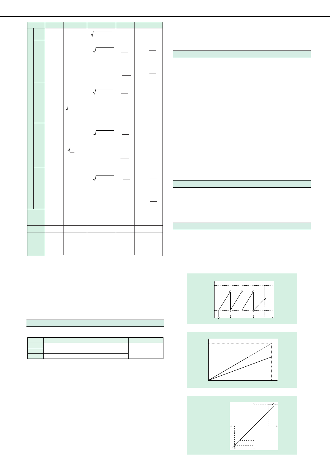
D/A output
7.5V
5.0V
2.5V
0.5V
0
D/A output
7.0V
5.0V
0
Displayed value
140%
100%
0%
–100%
–140%
For PF and deg, a
value between ±5 and
±7 V will not be
output. If an error
occurs, the output will
be approx. 7.5 V.
10Hz 100Hz 1kHz 10kHz
140% input of the rated value
t0: Rated value setting time
Output
7.0V
5.0V
0V
–5.0V
–7.0V
–100%–140%
Rated value input
D/A output
7.5V
7.0V
5.0V
0V
–5.0V
–7.0V
–7.5V
Displayed value50kHz
t0 Integration time
Displayed value
140%100%
Page 3

External Input (Optional)
Either /EX1 or /EX2 can be selected as a voltage-output-type current sensor.
/EX1: 2.5/5/10 V
/EX2: 50/100/200 mV
Specifications: See the “Input” item.
Comparator Output (Optional)
Output method: Normally open and normally closed relay contact outputs (in pairs)
Number of output channels and channel setup: 4 (settable for each channel)
Contact capacity: 24 V/0.5 A
D/A output (4 channels): See the “D/A Converter (Optional)” item.
External Control and Input Signals (only when the D/A or /CMP option has been installed)
External control and input/output signals:
Input level: TTL negative pulse
EXT-HOLD, EXT-TRIG, EXT-START, EXT-STOP, EXT-RESET,
INTEG-BUSY
Note:That the /DA4 or /DA12 option must be installed.
Note:Only EXT-HOLD and EXT-TRIG are available when the / CMP
option has been installed.
General Specifications
EMI standard: EN55011 Group 1 Class A
Safety standards: EN61010-1
Warm-up time: Approx. 30 min.
Operating temperature and humidity range: 5 to 40°C, 20 to 80% R.H. (no condensation)
Storage temperature: –25 to 60°C (no condensation)
Operating altitude: 2000 m or less
Insulation resistance: Between voltage input terminals and case
Withstanding voltage: Between voltage input terminals and case
Power supply: Any power supply voltage between 100 and 240 V; frequency: 50/
Vibration test conditions: Sweep test - Frequency: 8 to 150 Hz sweep, all three directions
Impact conditions: Impact test: Acceleration of 490 m/s
Power consumption:
External dimensions: WT200:Approx. W × H × D: 213 × 88 × 350 (mm) (not including
Weight: WT200:Approx. 3.0 (kg), 6.6 (lbs.)
Accessories: Power cord: UL/CSA, VDE, SAA or BS standard, 1 pc.
EN50082-2: 1995
Overvoltage Category II
Pollution degree 2
Between current input terminals and output terminals
Between voltage input terminals and current input terminals
Between voltage input terminals of each element
Between current input terminals of each element
Between voltage input terminals and power plug
Between current input terminals and power plug
Between case and power plug
The above values must be 50 MΩ or more at 500 V DC.
Between current input terminals and output terminals
Between voltage input terminals and current input terminals
Between voltage input terminals of each element
Between current input terminals of each element
Between voltage input terminals and power plug
Between current input terminals and power plug
The above values must be 3700 V for 1 minute at 50/60 Hz.
Between case and power plug: 1500 V for 1 minute at 50/60 Hz
60 Hz
Endurance test - Frequency: 16.7 Hz, all three directions; ampli-
Free-fall test - Height:100 mm, 1 time for each of four sides
WT200: 35 VA max., WT130: 50 VA max. (for power supply of 240 V)
WT200:25 VA max., WT130: 32 VA max. (for power supply of 100
V)
projections)
8-3/8 × 3-1/2 × 13-3/4 (inch) (not including projections)
WT130:Approx. W × H × D: 213 × 132 × 350 (mm) (not including
projections)
8-3/8 × 5-3/16 × 13-3/4 (inch) (not including projections)
WT130:Approx. 5.0 (kg), 11.0 (lbs.)
for 1 minute
tude of 4 mm for 2 hr
2
, all three directions
Harmonic Analysis Function (Optional)
Method: Synchronization to the fundamental frequency by using a phase
Frequency range: Fundamental frequency between 40 Hz and 440 Hz
Display resolution: 9999 (WT130), 9999 or 20000 (WT200)
Items analyzed: V, A, W, deg (WT200); V1, V2, V3, A1, A2, A3, W1, W2, W3, deg1,
Note that simultaneous analysis can be made for one specified input mode.
Sampling speed/method:
The sampling speed depends on the fundamental frequency to be input:
FFT number of points: 512 points FFT
FFT calculation accuracy:32 bits
Window: Rectangular window
Display update interval: Approx. 3 sec.
Accuracy: ±0.2% of range is added to the normal display accuracy.
■ Model and Suffix Codes
Suffix Code
Model Description
253421
-D
Power cord
-F
-R
-Q
Optional
features
/EX2
/HRM
/DA4
/CMP
Note: The WT200 communication feature cannot be modified or provided later after
delivery of the product.
Model Description
253502
253503
-C1
Interface
-C2
-0
Supply voltage
-D
Power cord
-F
-R
-J
/EX1
Optional features
/EX2
/HRM
/DA12
/CMP
■ Wiring and Model
Wiring
Single-phase, 2-wire
Single-phase, 3-wire
Three-phase, 3-wire (2-power-meter method)
■ External Dimension
250
213
Unit: mm
23
73
356
Three-phase, 3-wire (3-power-meter method)
Three-phase, 4-wire
■ Accessories
132
20
8819
23
356
179
13
213
Name
Rack-mount kit
Rack-mount kit
Rack-mount kit
Rack-mount kit
Rack-mount kit
Rack-mount kit
Rack-mount kit
Rack-mount kit
locked loop (PLL) circuit
deg2, deg3 (WT130), each harmonic component, total Vrms, total
Arms, total active power, PF of the fundamental wave, phase-angle
of fundamental wave, total harmonic distortion ratio in %, and contents ratio in %
Input
frequency
range
40% f<70Hz
70% f<130Hz
130% f<250Hz
250% f% 440Hz
Sampling
frequency
f×512Hz
f×256Hz
f×128Hz
f×64Hz
up to the n'th
1 period of f
2 period of f
4 period of f
8 period of f
WT200, 1-input element model
UL/CSA standard
VDE standard
SAA standard
BS standard
/C1
/C2
/EX1
GP-IB communication function
RS-232-C communication function
External input 2.5/5/10 V
External input 50/100/200 mV
Harmonic analysis function
4-channel D/A output
Comparator & D/A, each of 4 channels
Suffix Code
WT130, 2-input element model
WT130, 3-input element model
GP-IB communication function
RS-232-C communication function
Any power supply voltage between 100 and 240 V
UL/CSA standard
VDE standard
SAA standard
BS standard
External input 2.5/5/10 V
External input 50/100/200 mV
Harmonic analysis function
12-channel D/A output
Comparator & D/A, each of 4 channels
Model
253421
253502
u
-
-
-
-
Model or Part Number
751533-E2
751533-J2
751534-E2
751534-J2
751533-E3
751533-J3
751534-E3
751534-J3
Specifications
Single-mounted WT200 for EIA
Single-mounted WT200 for JIS
Dual-mounted WT200 for EIA
Dual-mounted WT200 for JIS
Single-mounted WT130 for EIA
Single-mounted WT130 for JIS
Dual-mounted WT130 for EIA
Dual-mounted WT130 for JIS
Window
harmonic
u
u
u
-
-
Order
50
50
50
30
Select one.
Select one.
Select one.
Select one.
Select one.
Select one.
253503
u
u
u
u
u
Order Quantity
1
1
1
1
1
1
1
1
Page 4

Related Products
■ WT2010/WT2030 Digital Power Meter
Enhanced power meter, incorporating a total harmonic analysis function conforming to the IEC standard.
■
WT1010/WT1030/WT1030M
General-purpose mid-class models suitable for a wide range of applications
Digital Power Meter
● Outstanding performance: 0.03%/DC, 2 Hz to 500 kHz
● High accuracy: 0.08% (45 to 66 Hz)
● Total harmonic current/Flicker conforming to IEC1000-3-2 and
-3 can be measured.
■ PZ4000 Power Analyzer
New concept power meter capturing power fluctuations as waveforms
● Frequency response: DC to 2 MHz
● Sampling speed: 5 MS/s maximum
● Fundamental power accuracy: ±(0.1% of rdg + 0.025% of rng)
● Voltage and current waveform display and analysis function
● Motor evaluation function (when equipped with 253771 mod-
ule)
● Frequency response: DC, 0.5 Hz to 300 kHz
● High accuracy: 0.2% (45 to 66 Hz)
● Overall efficiency of a motor can be measured by using the
motor evaluation function (only WT1030M).
■ DL708E/DL716 Digital Scope
For simultaneous measurement of voltage, temperature, distortion, and logic
● Inputs of up to 8 analog channels (DL708E)/16 analog channels + 32 logic bits (DL716)
● Eight types of mixed plug-in input units
● Record length of 64M words maximum (DL716’s 16M words/
ch. model)
● Built-in HDD (optional)
YOKOGAWA ELECTRIC CORPORATION
Measurement Sales Dept.
9-32, Nakacho 2-chome, Musashino-shi,
Tokyo 180-8750, JAPAN
Phone: 81-422-52-6614, Fax: 81-422-52-6624
YOKOGAWA CORPORATION OF AMERICA
2 Dart Road, Newnan, Georgia 30265, U.S.A.
Phone: 1-770-253-7000, Fax: 1-770-251-2088
YOKOGAWA EUROPE B.V.
Vanadiumweg 11, 3812 PX Amersfoort, THE NETHERLANDS
Phone: 31-33-4622142, Fax: 31-33-4641616
YOKOGAWA ENGINEERING ASIA PTE. LTD.
5 Bedok South Road, Singapore 469270
Phone: 65-2419933, Fax: 65-2412606
YOKOGAWA ELECTRIC CORPORATION
Test & Measurement Business Division
155 Takamuro-cho, Kofu-shi, Yamanashi-ken, 400-8558 Japan
Phone: 81-552-43-0310, Fax: 81-552-43-0396
Subject to change without notice.
All Rights Reserved, Copyright© 1995, Yokogawa Electric Corporation.
Represented by :
MM-07E
[Ed : 05/b] Printed in Japan, 009(YG)
 Loading...