

Page 1
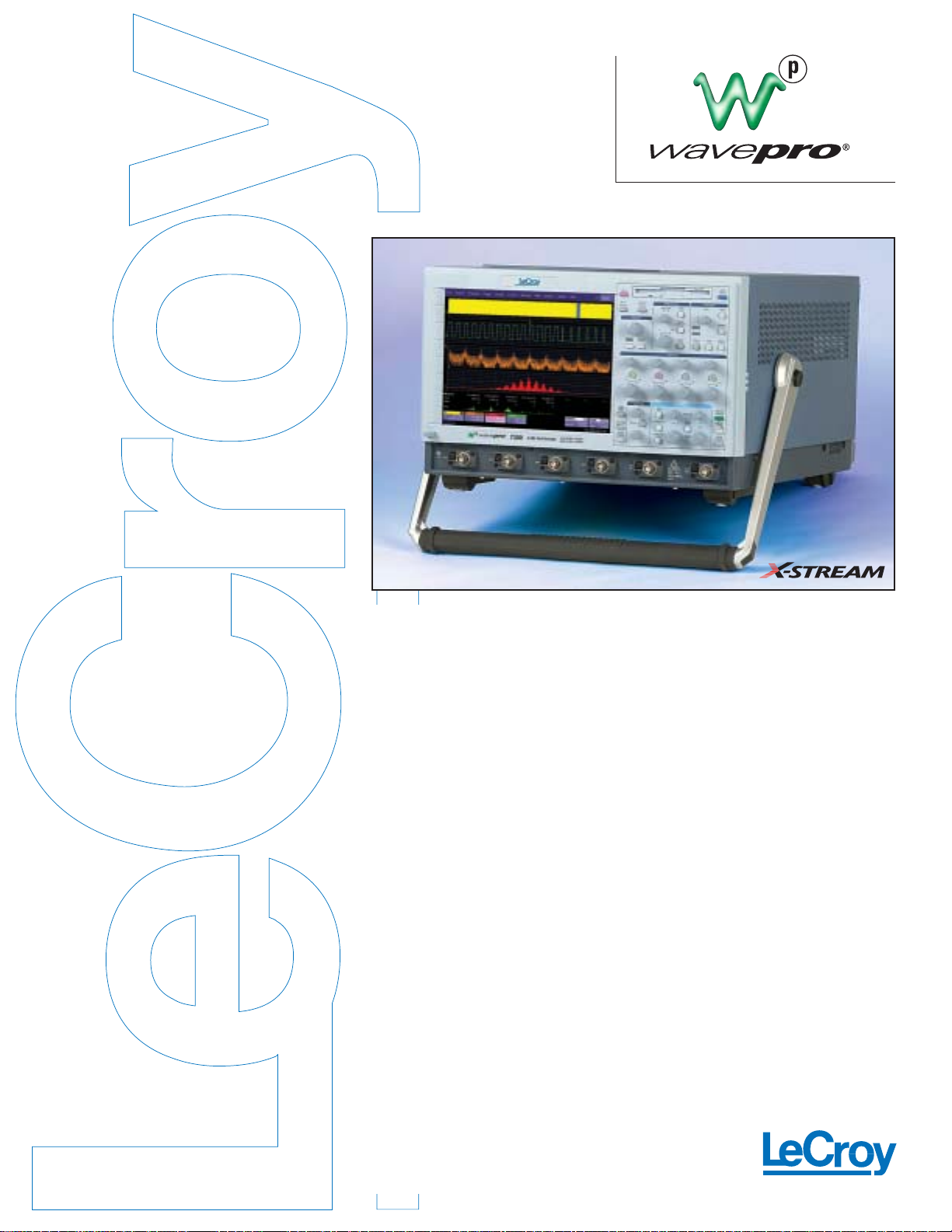
WavePro 7000
Series
7300
7200
7100
7000
LEADING FEATURES
• Up to 24 Mpts/Ch (48 Mpts for 2 Ch)
• Up to 10 GS/s on 4 Channels
(20 GS/s for 2 Ch)
• 1, 2, and 3 GHz Bandwidths
• 1 MΩ and 50 Ω Input Paths
• X- Stream Powered Technology
• Touch Screen and Front Panel
User Interface
• 10.4 “ SVGA Display
• Zoom and Multi-Zoom Display
• Automated Measurements
with Histicons
• Connectivity to USB, GPIB
and 802.3xx
• Customizable with XDEV
Developer’s Kit Option
• Expandable WaveShape Analysis
with XMAP Option
• Jitter Analysis
LeCroy’s WavePro 7000 Series brings the
ability to conduct next-generation waveform measurements and analysis —
not just “viewing” of signals — to 1 GHz,
2 GHz,and 3 GHz bandwidth applications.
The WavePro 7300 oscilloscope is the first to
offer high-speed integrated 1 MΩ and 50 Ω
inputs.Connect any passive or active probe,
and the WavePro DSO is ready to measure —
conveniently and accurately.
LeCroy h as integrated its groundbreaking
X-Stream
TM
Technology into the WavePro
family and combined it with the most
intuitive User Interface (UI) available.
Such ability gives you greater confidence in
the measurements you make. Confidence you
can only achieve through fast oversampling
of 10 GS/s on all channels,acquisition
memory of up to 48 million points to
maintain fast sampling—even for long
complex signals—and excellent jitter noise
floor performance.
The WavePro 7000 series can conduct
WaveShape Analysis 10–100 times faster
than any other oscilloscope in its class.
That makes them excellent tools for
next-generation designs,such as
datacom/telecom standards development,
Gigabit Ethernet,USB 2.0, digital design and
debugging,and advanced military designs.
Greater Signal Understanding
The WavePro 7000 series provides multiple
options so you can better understand the
signals in design. Just press Zoom to s ee
expanded detail of the waveform. See
graphical views like Histicons,Tracks, and
Trends of how a measurement changes
throughout the signal. Use 3-D Analog
Persistence to get better views of jitter and
then measure directly from the trace.
The WavePro 7100,7200,and 7300
units come with 1 M/channel memory,
standard at 1 GHz,the entry-level WavePro
7000 unit provides accessibility to LeCroy’s
X-Stream Technology at an exceptional price.
Optional application packages focus
the ability of the WavePro DSO to specific
measurements in optical and electrical
mask testing,magnetic and optical disk
drive measurements,and clock and timing
applications.Whether you’re viewing signals
or measuring timing and amplitude across
multiple channels,the WavePro 7000 series
has it all for less.
Page 2

Specifications
Ver tical System WavePro 7000 WavePro 7100 WavePro 7200 WavePro 7300
Analog Bandwidth @ 50 Ω (-3 dB) 1 GHz 1 GHz 2 GHz 3 GHz
Rise Time ( Typical) 400 ps 400 ps 225 ps 150 ps
Input Channels 4
Bandwidth Limiters 25 MHz;200 MHz
Input Impedance 50 Ω;1 MΩ//11pF typical (using PP005A probe)
Input Coupling 1 MΩ:AC,DC,GND;50 Ω:DC
Maximum Input Voltage 50 Ω:5 Vrms,1 MΩ:100 Vmax (peak AC:≤5 KHz + DC)
Channel-Channel Isolation 250:1 at same V/div setting, 40:1 at 3 GHz
Vertical Resolution 8 bits;up to 11 bits with enhanced resolution (ERES)
Sensitivity 50 Ω:2 mV – 1 V/div fully variable;1 MΩ:2 mV – 2 V/div fully variable
DC Gain Accuracy ±1.5% of full scale;±1% (typical)
Offset Range 50 Ω:±700 mV @ 2-4.99 mV/div
±1.5 V @ 5-100 mV/div
±10 V @ .102-1 V/div
1 MΩ:±700 mV @ 2-4.99 mV/div
±1.5 V @ 5-100 mV/div
±20 V @ 0.102-2 V/div
Offset Accuracy ±(1.5% of full scale + 0.5% of offset value + 2 mV)
Horizontal System
Timebases Internal timebase common to 4 input channels;an external clock may be applied at the auxiliary input
Time/Division Range 20 ps/div – 10 s/div
Math & Zoom Traces 4 independent zoom and 4 math/zoom traces standard;
8 math/zoom traces available with XMAP (Master Analysis package) or XMATH (Advanced Math package)
Clock Accuracy ≤ 10 ppm @ 0– 40 °C
Time Internal Accuracy ≤ 0.06 / SR + (10 ppm * Reading) (rms)
Sample Rate & Delay Time Accuracy ± 10 ppm ≤ 10 s interval
Jitter Noise Floor 2 ps rms @ 100 mV/div (typical)
Trigger & Interpolator Jitter ≤ 2.5 ps (typical)
Channel-Channel Deskew Range ±4.5 ns
External Clock 30 MHz – 1 GHz;50 Ω impedance; applied at the auxiliary input
Acquisition System
Single-Shot Sample Rate/Ch 5 GS/s 10 GS/s 10 GS/s 10 GS/s
2 Channel Max 10 GS/s 20 GS/s 20 GS/s 20 GS/s
Random Interleaved Sampling (RIS) 200 GS/s for repetitive signals:20 ps/div – 1 µs/div
Maximum Trigger Rate 150,000 waveforms/second (in Sequence Mode,up to 4 channels)
Intersegment Time ≤ 6 µs
Maximum Acquisition Points/Ch 4 Ch / (2 Ch) 4 Ch / (2 Ch) Sequence Mode
Standard 500k / 1M 1M / 2M 500 segments
M – Memory Option 4M / 8M 4M / 8M 1,000 segments
L – Memory Option —8M / 16M 5,000 segments
VL – Memory Option — 16M / 32M 10,000 segments
XL – Memory Option — 24M / 48M 20,000 segments
Acquisition Processing
Averaging Summed averaging to 1 million sweeps;continuous averaging to 1 million sweeps
Enhanced Resolution (ERES) From 8 . 5 to 11 bits ver tical resolution
Envelope (Extrema) Envelope,floor,roof for up to 1 million sweeps
Interpolation Linear, Sin x/x
Triggering System
Modes Normal,Auto,Single, and Stop
Sources Any input channel,Ex ternal, Ext X10, Ex t/10, or line; slope and level unique to each source (except line trigger)
Coupling mode DC50 Ω,GND,DC1MΩ,AC1MΩ
Pre-trigger delay 0–100% of horizontal time scale
Post-trigger delay 0–10,000 divisions
Hold-off by time or events Up to 20 s or from 1 to 99,999,999 events
Internal trigger range ±5 div from center
Max trigger frequency 1 GHz w/Edge Trigger; 1 GHz w/Edge Trigger; 2 GHz w/Edge Trigger; 3 GHz w/Edge Trigger;
750 MHz w/SMART Trigger 750 MHz w/SMART Trigger 750 MHz w/SMART Trigger 750 MHz w/SMART Trigger
Basic Triggers
Edge/Slope/Line Triggers when signal meets slope and level condition
SMART Triggers
®
State or Edge Qualified Triggers on any input source only if a defined state or edge occurred on another input source.
Delay between sources is selectable by time or events.
Dropout Triggers if signal drops out for longer than selected time between 2 ns and 20 s.
Patter n Logic combination (AND,NAND,OR, NOR) of 5 inputs (4 channels and external trigger input).
Each source can be high,low, or don’t care.The high and low level can be selected
independently.Triggers at start or end of the pattern.
SMART Triggers
with Exclusion Technology
Glitch Triggers on positive or negative glitches with widths selectable from 600 ps to 20 s or on intermittent faults.
Signal or Pattern Width Triggers on positive or negative pulse widths selectable from 600 ps to 20 s or on intermittent faults.
Signal or Pattern Interval Triggers on intervals selectable between 2 ns and 20 s.
Page 3

Automatic Setup
Auto Setup Automatically sets timebase,trigger, and sensitivit y to display a wide range of repetitive signals.
Vertical Find Scale Automatically sets the vertical sensitivity and offset for the selected channels to display a waveform with maximum dynamic range.
Probes
Probes (2) PP005A standard;Optional passive and active probes available.
Probe System: Probus Automatically detects and supports a variety of compatible probes.
Scale Factors Automatically or manually selected depending on probe used.
Color Waveform Display
Type Color 10.4" flat-panel TFT-LCD with high resolution touch screen
Resolution SVGA; 800 x 600 pixels
Real time Clock Dates,hours,minutes, seconds displayed with waveform.SNTP support to synchronize to precision internet clocks.
Number of Traces Display a maximum of 8 traces.Simultaneously display channel,zoom,memory,and math traces.
Grid Styles Auto,Single,Dual,Quad,Octal,XY, Single + XY,Dual + XY
Waveform Styles Sample dots joined or dots only
Analog Persistence Display
Analog & Color-Graded Persistence Variable saturation levels; stores each trace’s persistence data in memory.
Persistence Selections Select analog,color,or three-dimensional.
Trace Selection Activate persistence on all or any combination of traces.
Persistence Aging Time Select from 500 ms to infinity.
Sweeps Displayed All accumulated,or all accumulated with last trace highlighted
Zoom Expansion Traces
Display up to 4 Zoom and 4 Math/Zoom traces;
8 Math/Zoom traces available with XMAP (Master Analysis package) or XMATH (Advanced Math package).
CPU
Processor Intel 1.7 GHz or better with MS Windows 2000 Platform
Processing Memory Up to 1 Gbyte
Internal Waveform Memory
M1,M2,M3,M4 Internal Waveform Memory (store full-length waveforms with 16 bits/data point)
or store to any number of files limited only by data storage media
Setup Storage
Front Panel and Instrument Status Store to the internal hard drive,floppy drive or to a USB-connected peripheral device.
Interface
Remote Control Via Windows Automation,or via LeCroy Remote Command Set
GPIB Port (Optional) Supports IEEE – 488.2
Ethernet Port 10/100Base-T Ethernet interface
Floppy Drive Internal,DOS-format,3.5”high-density
USB Ports 4 USB ports support Windows compatible devices
External Monitor Port Standard 15-pin D-Type SVGA-compatible
Parallel Port 1 standard
Auxiliary Output
Signal Types Select from calibrator or control signals output on front panel
Calibrator Signal 5 Hz – 5 MHz square wave or DC level;0.0 to 5.0 V into 50 Ω (0-1 V into 1 MΩ) or TTL volts (selectable)
Control Signals Trigger enabled,trigger out,pass/fail status
Auxiliary Input
Signal Types Selected from External Trigger or External Clock input on front panel
General
Auto Calibration Ensures specified DC and timing accuracy is maintained for 1 year minimum
Power Requirements 100–120 VAC at 50/60/400 Hz;200–240 VAC at 50/60 Hz; Automatic AC Voltage selection
Power consumption:< 800 VA
Environmental
Temperature (Operating) +5˚C to +40 ˚C including floppy disk and CD-ROM drives
Temperature (Non-Operating) -20˚C to +60˚C
Humidity (Operating) 5% to 80% relative humidity (non-condensing) up to +30 ˚C. Upper limit derates to 25% relative humidity (non-condensing) at +40˚C
Humidity (Non-Operating) 5% to 95% relative humidity (non-condensing) as tested per MIL-PRF-28800F
Altitude (Operating) up to 10,000 ft (3048 m) at or below +25˚C
Altitude (Non-Operating) up to 40,000 ft (12,192 m)
Random Vibration (Operating) 0.31 g rms 5 Hz to 500 Hz,15 minutes in each of three orthogonal axes
Random Vibration (Non-Operating) 2.4 g rms 5 Hz to 500 Hz,15 minutes in each of three orthogonal axes
Functional Shock 20 g peak,half sine,11 ms pulse,3 shocks (positive and negative) in each of three orthogonal axes, 18 shocks total
Physical Dimensions
Dimensions (HWD) 264 mm x 397 mm x 491 mm;10.4”x 15.6”x 19.3”(height excludes feet)
Weight 18 kg;39 lbs.
Shipping Weight 24 kg;53 lbs.
Certifications
CE Approved,UL and cUL listed;conforms to EN 61326-1, EN 61010-1, UL 3111-1, and CSA C22.2 No. 1010.1
Warranty and Service
2-year warranty; calibration recommended annually. Optional service programs include extended warranty, upgrades, and calibration services
Specifications
Page 4

Sales and Service
Throughout the World
Corporate Headquarters
700 Chestnut Ridge Road
Chestnut Ridge, NY 10977
USA
http://www.lecroy.com
LeCroy Sales Offices:
Asia: Hong Kong
Phone (852) 2834 5630
Fax (852) 2834 9893
Austria: Markersdorf
Phone (43) 2749 30050
Fax (43) 2749 30051
Benelux: The Netherlands
Phone (31) 40 211 6998
Fax (31) 40 211 6999
France: Les Ulis
Phone (33) 1 69 18 83 20
Fax (33) 1 69 07 40 42
Germany: Heidelberg
Phone (49) 6221 827 00
Fax (49) 6221 834 655
Italy:Venice
Phone (39) 041 456 97 00
Fax (39) 041 456 95 42
Japan: Osaka
Phone (81) 6 6396 0961
Fax (81) 6 6396 0962
Japan: Tokyo
Phone (81) 3 3376 9400
Fax (81) 3 3376 9587
Korea: Seoul
Phone (82) 2 3452 0400
Fax (82) 2 3452 0490
Spain: Madrid
Phone: (34) 91 640 11 34
Fax: (34) 91 640 06 40
Switzerland: Geneva
Phone (41) 22 719 2228
Fax (41) 22 719 2230
U.K.: Abingdon
Phone (44) 1 235 536 973
Fax (44) 1 235 528 796
U.S.A.: Chestnut Ridge
Phone (1) 845 578 6020
Fax (1) 845 578 5985
WPRO DS pdf/cc
7200 6/03
© 2003 by LeCroy Corporation.All rights reser ved.
LeCroy,ActiveDSO, ProBus, SMART Trigger, WavePro, and Waverunner are registered trademarks of LeCroy Corporation.
JitterTrack,WaveMaster, and X-Stream are trademarks of LeCroy Corporation. Information in this publication supersedes all
earlier versions. Specifications subject to change without notice.
WavePro 4-Channel Digital Oscilloscopes Product Code
3 GHz 20 GS/s (2 Ch);10 GS/s 4 Ch 1 MΩ & 50 Ω Color DSO WavePro 7300
2 Mpts/2 Ch;1 Mpts/Ch Standard
2 GHz 20 GS/s (2 Ch);10 GS/s 4 Ch 1 MΩ & 50 Ω Color DSO WavePro 7200
2 Mpts/2 Ch;1 Mpts/Ch Standard
1 GHz 20 GS/s (2 Ch);10 GS/s 4 Ch 1 MΩ & 50 Ω Color DSO WavePro 7100
2 Mpts 2 Ch;1Mpts/Ch Standard
1 GHz 10 GS/s (2 Ch);5 GS/s 4 Ch 1 MΩ & 50 Ω Color DSO WavePro 7000
1 Mpts 2 Ch;500kpts/Ch Standard
Included with Standard Configuration
10:1 10 MΩ Passive Probes (Qty 2) PP005A
Operators Manual;Quick Reference Guide;CD-ROM with OM/RCM and Utility software and Recover y sof tware
Remote Control Manual
Floppy Disk Drive
CD-ROM Drive
Optical 3 button Wheel Mouse- USB
Standard Ports;10/100Base-T Ethernet,Parallel,SVGA Video Output,USB
Protective Front Co v e r
Standard Commercial Calibration and Performance Certificate
2 Year Warranty
Memory Options
8 Mpts/2 Ch,4 Mpts/Ch -M
16 Mpts/2 Ch,8 Mpts/Ch -L
32 Mpts/2 Ch,16 Mpts/Ch -VL
48 Mpts/2 Ch,24 Mpts/Ch -XL
Note: The WavePro 7000 unit’s maximum memory is “M” option
Hardware Options
IEEE-488 Remote Control Interface GPIB-1
Removable Hard Drive Option RHD
WaveShape Analysis Packages
X-Stream Math,Processing and Developer’s Kit (includes XMATH, XDEV,JTA2) XMAP
Advanced Math Analysis Package XMATH
Developer’s Customization Kit XDEV
Jitter and Timing Analysis JTA2
Digital Filter Package DFP2
Serial Data Mask Testing Package SDM
Disk Drive Measurement Package DDM2
LeCroy M 1 Timing Tool M1/ADV-1
Selected Accessories
10:1 10 MΩ Passive Probes PP005A
3.5 GHz Active Voltage Probe HFP3500
2.5 GHz Active Voltage Probe HFP2500
1.5 GHz Active Voltage Probe HFP1500
WaveLink 4 GHz Differential Probe D300/D300AT
Differential Probe AP034
Differential Probe ADP300 series
Current Probe CP and AP series
O/E Converters 500–1630 nm OE 425/455
Keyboard KYBD-1
Oscilloscope Cart OC1021
Oscilloscope Cart with additional shelf and drawer OC1024
Rackmount- 25" Slide RMA-25
Rackmount- 30" Slide RMA-30
AntiVirus Software AV
Ordering Information
 Loading...